Publicité
Liens rapides
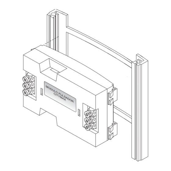
MODULO PULSADOR CITYMAX
PUSH-BUTTON CITYMAX MODULE
Cod. 94553
V. 04/00
Instalación del módulo / Module installation
CARACTERISTICAS TECNICAS
TECHNICAL FEATURES
ALIMENTACION
9 ~ 12 Vac
50 ~ 60 Hz
POWER SUPPLY
9 ~ 12 Vdc
CONSUMO
0 mA (iluminación apagada)
CONSUMPTION
20 mA (iluminación encendida)
TEMPERATURA
-10 ~ +60 ºC
TEMPERATURE
Esquema para sistemas de audio / Audio system wiring
A LAS PLANTAS
TO THE FLOORS
HIGH RESOLUTION
FLAT MONITOR
1
2
1
2
3
6
F U
321
CN1
LL12
LL10
LL8
LL6
LL4
LL2
El hilo de llamada de cada borna
coincide con el pulsador del mismo
lado y posición
The call wire of every terminal
matches with the pushbutton on the
same side and position
9 ~ 12 Vac
50 ~ 60 Hz
9 ~ 12 Vdc
Solicite nuestro Esquemario de Sistemas Citymax para obtener más deta-
0 mA (lighting off)
lles de la instalación. Ask for our Citymax Systems Schematic diagrams to
20 mA (lighting on)
-10 ~ +60 ºC
get further details of the installation.
PRIM
+ -
+ -
-
-
1 2 3 6
Ab Ab
Cp2
Tc
Cp1
LL11
LL9
LL7
LL5
LL3
LL1
Conexión a siguientes módulos
de pulsadores (si existen)
Connection to the next push-
button modules (if exist)
Esquema para sistemas de audio y vídeo / Audio & video system wiring
A LAS PLANTAS
TO THE FLOORS
HIGH RESOLUTION
FLAT MONITOR
1
2
1
2
Vac
3
6
-
+
Ct
F U
321
CN1
1 2 3 6
Ab Ab
Cp2
Tc
Cp1
+
-
CT
V
M
LL12
LL10
LL8
LL6
LL4
LL2
Solicite nuestro Esquemario de Sistemas Citymax para obtener más deta-
lles de la instalación. Ask for our Citymax Systems Schematic diagrams to
get further details of the installation.
Vac
PRIM
+ -
+ -
Vac
+ -
+ -
PRIM
LL11
LL9
LL7
LL5
LL3
LL1
Conexión a siguientes módulos
de pulsadores (si existen)
Connection to the next push-
button modules (if exist)
Publicité

Sommaire des Matières pour Fermax CITYMAX
- Page 1 0 mA (iluminación apagada) CONSUMPTION 0 mA (lighting off) lles de la instalación. Ask for our Citymax Systems Schematic diagrams to lles de la instalación. Ask for our Citymax Systems Schematic diagrams to 20 mA (iluminación encendida) 20 mA (lighting on) TEMPERATURA -10 ~ +60 ºC...
- Page 2 CONSOMMATION 5 mA (éclairage éteint) VERBRAUCH 5 mA (licht an) blage pour Systèmes Citymax. Fragen Sie nach unseren schemen für Citymax blage pour Systèmes Citymax. Fragen Sie nach unseren schemen für Citymax 25 mA (éclairage allumé) 25 mA (licht aus) TEMPÉRATURE...


