Publicité
Les langues disponibles
Les langues disponibles
Liens rapides
!
WARNING
TO REDUCE THE RISK OF FIRE, ELECTRIC SHOCK, OR
INJURY TO PERSONS, OBSERVE THE FOLLOWING:
• Use this unit only in the manner intended by the manufacturer. If you have
questions, contact the manufacturer at the address or telephone number
listed in the warranty.
• Before servicing or cleaning unit, switch power off at service panel and lock the
service disconnecting means to prevent power from being switched on
accidentally. When the service disconnecting means cannot be locked,
securely fasten a prominent warning device, such as a tag, to the service panel.
• Installation work and electrical wiring must be done by a qualified person(s)
in accordance with all applicable codes and standards, including fire-rated
construction codes and standards.
• Sufficient air is needed for proper combustion and exhausting of gases
through the flue (chimney) of fuel burning equipment to prevent backdrafting.
Follow the heating equipment manufacturer's guideline and safety standards
such as those published by the National Fire Protection Association (NFPA),
and the American Society for Heating, Refrigeration and Air Conditioning
Engineers (ASHRAE), and the local code authorities.
• When cutting or drilling into wall or ceiling, do not damage electrical wiring
and other hidden utilities.
• Ducted fans must always be vented to the outdoors.
• Do not use this unit with any separate solid-state speed control device.
• To reduce the risk of fire, use only metal ductwork.
• This unit must be grounded.
• When installing, servicing or cleaning the unit, it is recommended to wear
safety glasses and gloves.
• When applicable local regulations comprise more restrictive installation and/or
certification requirements, the aforementioned requirements prevail on those
of this document and the installer agrees to conform to these at his own expense.
For complete warranty statement and service parts, or to learn more about the instructions below,
please type your model number in on our website or scan the QR code.
To obtain a paper copy of the detailed instructions, please call us.
RECOMMENDED TOOLS AND ACCESSORIES
• Measuring tape
• Phillips screwdriver no. 2
• Nut driver or socket 3/8"
1. INSTALL THE DUCTWORK (DUCTED
INSTALLATION ONLY)
NOTE: To reduce the risk of fire, use only metal ductwork.
1. Decide where
the ductwork
R
OOF CAP
will run between
the powerpack
insert and the
outside. (FIG. 1)
2. A straight, short
P
OWERPACK
duct run will
INSERT
allow the hood
to perform most
efficiently.
24"
- 30"
3. Long duct runs,
MIN
MAX
ABOVE COOKING SURFACE
e l b o w s , a n d
transitions will
reduce the performance of the hood. Use as few of them as possible.
Larger ducting may be required for best performance with longer duct runs.
4. Install wall cap or roof cap (sold separately). Connect metal ductwork to
cap and work back towards the hood location. Use 2" metal foil duct tape
to seal the joints between ductwork sections.
2. REMOVE THE ADAPTER/DAMPER AND
6-IN. ROUND DAMPER
Detach and set aside the 3¼" x 10" adapter/damper and the 6-in.-round
damper (grey parts in FIG. 2) from back and side of the powerpack insert by
removing their 2 retaining screws. Discard the screws.
3. REMOVE THE CABINET BRACKETS
Detach the cabinet brackets (grey part in FIG. 3) from the back of the
powerpack insert by removing its 3 retaining screws. Discard the screws.
SCREWS
Fold up and down the bracket until it is split in two separate parts (FIG. 4).
Keep the brackets for possible further use.
NOTE: Both cabinet brackets have one wide edge and one narrow edge
(FIG. 5), to cover all installation configurations depending on cabinet widths.
Narrow edge
Wide edge
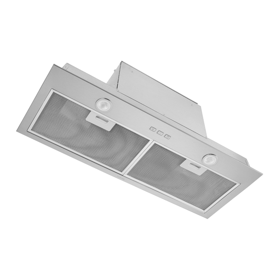
INSTALLATION, USE, AND CARE QUICK START MANUAL
POWERPACK INSERT MODELS BBN3306SS AND BBN3306SSC
READ AND SAVE THESE INSTRUCTIONS
!
Intended for domestic cooking only
TO REDUCE THE RISK OF A RANGE TOP GREASE FIRE:
A. Never leave surface units unattended at high settings. Boilovers cause smoking
and greasy spillovers that may ignite. Heat oils slowly on low or medium settings.
B. Always turn hood ON when cooking at high heat or when flambeing food
(i.e. Crepes Suzette, Cherries Jubilee, Peppercorn Beef Flambé).
C. Clean ventilating fans frequently. Grease should not be allowed to accumulate
on fan or filter.
D. Use proper pan size. Always use cookware appropriate for the size of the
surface element.
TO REDUCE THE RISK OF INJURY TO PERSONS IN THE
EVENT OF A RANGE TOP GREASE FIRE, OBSERVE THE
FOLLOWING:*
1. SMOTHER FLAMES with a close-fitting lid, cookie sheet, or metal tray, then
turn off the burner. BE CAREFUL TO PREVENT BURNS. If the flames do not
go out immediately, EVACUATE AND CALL THE FIRE DEPARTMENT.
2. NEVER PICK UP A FLAMING PAN - You may be burned.
3. DO NOT USE WATER, including wet dishcloths or towels - violent steam
explosion will result.
4. Use an extinguisher ONLY if:
A. You know you have a Class ABC extinguisher and you already know how to
operate it.
B. The fire is small and contained in the area where it started.
C. The fire department is being called.
D. You can fight the fire with your back to an exit.
* Based on "Kitchen Fire Safety Tips" published by NFPA.
For ADA compliance installation guidelines, please type the model number into our website.
• Flat blade screwdriver
(to open knock-out holes)
• Saw (to cut holes in cabinet)
4. PREPARE THE CABINET
The cabinet must be secured to wall studs or other wooden framework behind the drywall to support the weight of this
unit. Failure to do so may cause personal injury or damage to countertop or cooktop.
8"
6"
OR
ROUND DUCT
NOTES: A. The unit has to be installed inside the cabinet.
3¼"
10"
OR
X
DUCT
B. The unit should be mounted centered laterally over the cooktop burners.
C. For back to front position, the unit must be mounted according to local building codes.
H
1. Cut a hole in the bottom of the cabinet, using the dimensions shown (FIG. 6).
OUSE WIRING
2. Measure the remaining material of the cabinet bottom sides (C in FIG. 7), if it is 1/4" or more, there is no need to use the cabinet brackets. Go to step 7.
W
ALL CAP
3. When there is less than 1/4" remaining material (C), carefully remove those strips. Measure the cabinet inner width (D in FIG. 7). Refer to the table below
to see which cabinet bracket edge configuration must be used.
3¼"
10"
X
DUCT
FIG. 1
4. Pay attention to the Ease of Install hooks location on the unit (distance given from unit front flange, FIG. 8). Measure and mark the position of the Ease
of Install hooks (shown as E in FIG.9) on both cabinet side walls. Remove the unit.
CUT A HOLE IN THE BOTTOM
OF THE CABINET
FIG. 2
5. Install the cabinet brackets as follow (FIG. 9):
Align the bracket flush with the bottom of
the right cabinet side panel, with the
hooks marked position (E) between the
bottom embossed holes. For the narrow
edge configuration, trace a line on
the top of the bracket. For wide edge
configuration, trace a line at the bottom
of the central slots.
Lift the bracket flush with the marked
lined. Assemble the bracket to the
FIG. 3
cabinet side panel using 2 no. 8 x 5/8"
wood screws (included in parts bag)
through the upper holes.
NOTE: Do not use the embossed holes to
attach the bracket to the cabinet.
Repeat steps
cabinet side panel.
FIG. 4
FIG. 5
!
WARNING
In the United States
broan-nutone.com
1-800-558-1711
• Sheet metal shears
• Pliers
• Metal foil duct tape
N
ARROW EDGE
From 28-1/16" to < 28-1/2"
FIG. 6
A = 10¼"
B = 28 ¹/
"
16
Narrow edge
configuration
Wide edge
configuration
to
for the left
!
• For indoor residential use only.
• To reduce risk of fire and to properly exhaust air, be sure to duct air
outside. Do not vent exhaust air into spaces within walls or ceilings
or into attics, crawl spaces, or garages.
• Take care when using cleaning agents or detergents.
• Avoid using food products that produce flames under the Range
Hood.
• For general ventilating use only. Do not use to exhaust hazardous
or explosive materials and vapors.
• To avoid motor bearing damage and noisy and/or unbalanced
impellers, keep drywall spray, construction dust, etc. off power
unit.
• Your hood motor has a thermal overload which will automatically
shut off the motor if it becomes overheated. The motor will restart
when it cools down. If the motor continues to shut off and restart,
have the hood serviced.
• The bottom of the hood MUST NOT BE LESS than 24" and
recommended at a maximum of 30" above the cooktop for best
capture of cooking impurities.
• Use only with range hood cord connection kits that have been
investigated and found acceptable for use with this model range
hood.
• Please read specification label on product for further information
and requirements.
In Canada
broan-nutone.ca
1-800-567-3855
• Scissors (to cut metal foil duct tape)
• Pencil
• Wire stripper
!
WARNING
W
IDE EDGE
D
D
From 28-1/2" to 29"
8¼"
FIG. 7
E
FLUSH
FLUSH
E
FLUSH
EN
!
CAUTION
• 2 Appropriate wire nuts
• Strain relief, 7/8" diameter (to secure
house wiring cable to the hood)
UNIT TOP VIEW
4½"
FRONT
FIG. 8
FIG. 9
1105018C
Publicité

Manuels Connexes pour Broan-NuTone BBN3 Serie


Sommaire des Matières pour Broan-NuTone BBN3 Serie
- Page 1 In the United States In Canada For complete warranty statement and service parts, or to learn more about the instructions below, broan-nutone.com broan-nutone.ca please type your model number in on our website or scan the QR code. 1-800-558-1711 1-800-567-3855 To obtain a paper copy of the detailed instructions, please call us.
- Page 2 4. PREPARE THE CABINET ( ’ 5. PREPARE THE UNIT ( ’ 6. INSTALL THE UNIT ( ’ CONT CONT CONT NOTE: If, for any reason, the unit ’ 6. Measure the distance ORIZONTAL EXHAUST INSTALLATION ONLY CONT has to be removed from between both bottom the cabinet, it is possible bracket edges (F)
- Page 3 8. WIRING 12. OPERATION Soft-touch control panel WARNING Risk of electric shock. Electrical wiring must be done by qualified personnel in accordance with all applicable codes and standards. Before connecting wires, switch power off at service panel and lock service disconnecting means to prevent power from being switched on accidentally.
- Page 4 Aux États-Unis Au Canada Pour obtenir l’énoncé de garantie, la liste de pièces de remplacement, ainsi que les instructions www.broan-nutone.com www.broan-nutone.ca détaillées, inscrire votre numéro de modèle sur notre site Internet ou balayer le code QR. Pour obtenir une copie papier des instructions détaillées, appelez-nous.
- Page 5 4. PRÉPARATION DE L’ARMOIRE ( 5. PRÉPARATION DE L’APPAREIL ( 6. INSTALLATION DE L’APPAREIL ( SUITE SUITE SUITE NOTE : Si, pour quelque raison 6.Mesurer la distance NSTALLATION EN ÉVACUATION HORIZONTALE SEULEMENT SUITE que ce soit, l’appareil entre les rebords du bas devait être enlevé...
- Page 6 8. BRANCHEMENT ÉLECTRIQUE 12. FONCTIONNEMENT Commande à effleurement AVERTISSEMENT Risque d’électrocution. Le raccordement électrique doit être effectué par du personnel qualifié conformément aux codes et aux standards en vigueur. Avant d’effectuer le branchement, coupez l’alimentation électrique au panneau de distribution et verrouillez-le pour éviter une mise en NOTES : 1.
- Page 7 Estados Unidos Canadá Para información completa sobre la garantía y las piezas o para obtener instrucciones más www.broan-nutone.com www.broan-nutone.ca detalladas, escribe su número de modelo en nuestro sitio web o escanear el códeo QR. 1-800-558-1711...
- Page 8 4. PREPARACIÓN DEL GABINETE ( 5. PREPARACIÓN DEL APARATO ( 6. INSTALACIÓN DEL APARATO ( CONT CONT CONT 6 . M e d i r l a d i s t a n c i a NOTA: En el caso de que, por NSTALACIÓN CON SALIDA HORIZONTAL SOLAMENTE CONT entre ambos bordes...
- Page 9 8. CONEXIÓN ELÉCTRICA 12. FUNCIONAMIENTO Control táctil ADVERTENCIA Peligro de choque eléctrico. La instalación eléctrica debe ser hecha por personal calificado de acuerdo con todos los códigos aplicables y normas. Antes de efectuar el empalme, cortar la alimentación eléctrica del interruptor y cerrar con securidad para prevenir una NOTAS: 1.