Table des Matières
Publicité
Les langues disponibles
Les langues disponibles
Liens rapides
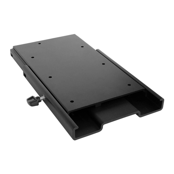
For use with all Minn Kota
®
PowerDrive™, Pontoon PowerDrive™, Ulterra™ and Terrova
Pontoon Hand Control Bracket and the DeckHand 40.
Item /
Part #
Description
Assembly
A
Includes
2990114
QCK REL PLATE/THUMB SCREW ASM
2-10
2
✖
PLATE-MNT,TOP PD QUICK RELEASE
4
✖
PLATE-MNT,BTM PD/AP QK/RL
6
2373421
SCREW-5/16-18 X 3/8 SHCS S/S
8
9951778
LOCKWASHER-1/4" ZINC
10
2011385
SCREW-TENSION/NEW KNOB
p
2374914
INSTR SHEET-PD/AP QK RL BRK
B
Includes
2994932
BAG ASM, ELEC. STEER QRB
12-18
12
2371728
WASHER-FENDER 1/4 X 1 1/4 ZP
14
2373413
SCREW-1/4-20 X 7/8 HHCS ZP
16
2263104
NUT-1/4-20 NYLOCK ZP
18
2373516
BOLT-1/4-20 X 2" HHC ZP
p Not shown on Parts Diagram.
✖ This part is included in an assembly and cannot be ordered individually.
TOOLS AND RESOURCES REQUIRED
• #3 Phillips Screw Driver
• Drill
MOUNTING CONSIDERATIONS
It is recommended that the motor be mounted as close to the
centerline of the boat as possible. The motor must not encounter
any obstructions as it is lowered into the water or raised into the
boat when stowed and deployed. Make sure the motor rest is
positioned far enough beyond the edge of the boat. Make sure the
area under the mounting location is flat, clear to drill holes and
install nuts and washers.
NOTICE:
Images are a graphical representation and may
vary slightly from your motor.
NOTICE:
In order for the MKA-16-03 bracket to be
engaged and dis-engaged, the motor must be in the
stowed position.
1 | minnkotamotors.com
Qty.
1
18
18
1
1
1
1
1
1
1
A A
4
4
8
4
• 9/32" Drill Bit
• 7/16" Box End Wrench
Complete Typical Installation
MKA-16-03 ELECTRIC-STEER
QUICK RELEASE BRACKET
®
freshwater trolling motors, the PowerDrive™
B B
14
14
12
12
16
16
6 6
• A second person to help with
the installation
©2020 Johnson Outdoors Marine Electronics, Inc.
1854035
2 2
4 4
8 8
10
10
Publicité
Table des Matières

Manuels Connexes pour MINN KOTA MKA-16-03

Sommaire des Matières pour MINN KOTA MKA-16-03
- Page 1 NOTICE: Images are a graphical representation and may vary slightly from your motor. NOTICE: In order for the MKA-16-03 bracket to be engaged and dis-engaged, the motor must be in the stowed position. ©2020 Johnson Outdoors Marine Electronics, Inc. 1 | minnkotamotors.com...
- Page 2 The MKA-16-03 Electric Steer Quick Release Bracket is designed to work on a number of Minn Kota trolling motors. The base extrusion or mounting bracket of the trolling motors may vary. Please note the appearance of the applicable trolling motors and mounting brackets.
- Page 3 INSTALLATION Installing the Top Plate to a PowerDrive or Terrova Make sure that the Power Cables from the battery are disconnected, or that the breaker, Power Cables Power Cables if equipped, is "off." WARNING Make sure the motor is mounted on a level surface and is not connected to a power source.
- Page 4 ITEM(S) NEEDED #A x 1 Take the Quick Release Bracket Assembly Top Plate Top Plate Quick Release Bracket Assembly Quick Release Bracket Assembly (Assembly #A) and remove the Tension Screw Knob and Lock Washer. Set the Tension Screw Knob and Bottom Bottom Slide...
- Page 5 After the Top Plate is secured to the Base Extrusion, reassemble the Top Plate to the Bottom Plate by sliding it in place and securing with the Lock Washer and Tension Screw Knob. Base Extrusion Base Extrusion Replace the Right Sideplate. Left Sideplate Left Sideplate m.
- Page 6 Installing the Top Plate to a Pontoon Hand Control Bracket ITEM(S) NEEDED #A x 1 #14 x 4 #16 x 4 Position the Pontoon Hand Control Bracket over the Outboard Outboard Outboard Outboard Top Plate (Assembly #A) and mount the Bracket Mounting Mounting Nylock...
- Page 7 Damper Damper NOTICE: The Hex Head Bolts (Item #14) and Nylock Nuts (Item #16) that came with the MKA-16-03 are not used when installing the Bracket to an Ulterra. Instead, the Hex Head Bolts Hex Head Hex Head Bolt Bolt...
- Page 8 Slide the Base Extrusion into place under the Bolts that were just installed. Power Tilt Power Tilt The Base Extrusion should slide between the Top Plate and the Clipped Washers. Hold the Clipped Washers up on the Stainless Steel Screw, so the Clipped Washer will sit on top of the Base Extrusion.
- Page 9 Replace the Right Sideplate. Replace the Left Sideplate. m. Replace the four sideplate Screws using a #2 or #3 Phillips Screw Driver. Screw Screw Right Sideplate Right Sideplate Left Sideplate Left Sideplate Screw Screw Screw Screw Screw Screw Installing the Bottom Plate Place the mount with the Quick Release Bracket attached as close to the center line or keel of the boat as possible.
- Page 10 Mark the side edges and rear of the Bottom Plate on Outboard Outboard Outboard Outboard the bow of the boat. Bow of Bow of Bottom Bottom Boat Boat Plate Plate Remove the Tension Screw Knob and Lock Washer Bow of Bow of and slide the motor and Top Plate inboard and off to Boat...
- Page 11 Tension Tension Screw Knob Screw Knob For warranty information, please visit minnkotamotors.com. Minn Kota Consumer & Technical Service 121 Power Drive Johnson Outdoors Marine Electronics, Inc. Mankato, MN 56001 PO Box 8129 Phone (800) 227-6433 ©2020 Johnson Outdoors Marine Electronics, Inc.
-
Page 12: Support À Dégagement Rapide Àcommande Électrique Mka-16
SUPPORT À DÉGAGEMENT RAPIDE À COMMANDE ÉLECTRIQUE MKA-16-03 1854035 À utiliser avec tous les moteurs de pêche à la traîne pour eau douce Minn Kota PowerDrive , Pontoon PowerDrive , Ulterra Terrova , le support à commande manuelle de PowerDrive Pontoon et DeckHand 40. - Page 13 Le support à dégagement rapide à commande électrique MKA-16-03 est conçu pour fonctionner sur plusieurs moteurs de pêche à la traîne Minn Kota. L’extrusion de la base ou le support de montage des moteurs de pêche à la traîne peut varier. Veuillez noter l’apparence des moteurs de pêche à...
-
Page 14: Installation De La Plaque Supérieure Sur Un Powerdrive Ou Un Terrova
INSTALLATION Installation de la plaque supérieure sur un PowerDrive ou un Terrova Assurez-vous que les câbles d’alimentation de la batterie sont déconnectés, ou que le disjoncteur, le Câbles d’alimentation Câbles d’alimentation cas échéant, est en position « arrêt ». AVERTISSEMENT Assurez-vous que le moteur est installé... -
Page 15: Article(S) Requis
ARTICLE(S) REQUIS #A x 1 Prenez l’ensemble du support à dégagement rapide Plaque supérieure Plaque supérieure Ensemble de support à Ensemble de support à (ensemble nº A) et retirez le bouton à vis de tension dégagement rapide dégagement rapide Coulisse Coulisse et la rondelle de blocage. -
Page 16: Installation De La Plaque Supérieure Sur Un Deckhand
Lorsque la plaque supérieure est fixée à l’extrusion de la base, remontez la plaque supérieure sur la plaque inférieure en la glissant en place et la fixant à l’aide de la rondelle de blocage et le bouton à vis Extrusion de la base Extrusion de la base de tension. -
Page 17: Installation De La Plaque Supérieure Sur Un Support De Commande Manuelle Pontoon
Installation de la plaque supérieure sur un support de commande manuelle Pontoon ARTICLE(S) REQUIS #A x 1 #14 x 4 #16 x 4 Positionnez le support de commande manuelle Hors-bord Hors-bord Hors-bord Hors-bord Écrou Écrou Pontoon au-dessus de la plaque supérieure Nylock Nylock Trous de... - Page 18 AVIS : Les boulons à tête hexagonale (article nº 14) et les écrous Nylock (article nº 16) livrés avec le MKA-16-03 ne sont pas utilisés lors de l’installation d’un support sur un Ulterra. Les boulons Boulon à tête Boulon à tête à...
- Page 19 Faites glisser en place l’extrusion de la base sous les boulons que vous venez d’installer. Mécanisme d’inclinaison motorisé Mécanisme d’inclinaison motorisé L’extrusion de la base devrait glisser entre la plaque supérieure et les rondelles taillées. Tenez les rondelles taillées sur la vis en acier inoxydable afin que la rondelle taillée soit placée sur l’extrusion de la base.
-
Page 20: Installation De La Plaque Inférieure
Replacez la plaque latérale droite. Replacez la plaque latérale gauche. m. Replacez les quatre vis de la plaque latérale en utilisant un tournevis cruciforme nº 2 ou nº 3. Plaque latérale droite Plaque latérale droite Plaque latérale Plaque latérale gauche gauche Installation de la plaque inférieure Placez le support en fixant le support à... - Page 21 Marquez les bords latéraux et arrière de la plaque Hors-bord Hors-bord Hors-bord Hors-bord inférieure sur l’étrave de votre bateau. Étrave du Étrave du Plaque Plaque bateau bateau Retirez le bouton à vis de tension et la rondelle inférieure inférieure de blocage, et faites glisser le moteur et la plaque Étrave du Étrave du supérieure vers l’intérieur pour le retirer de la...
- Page 22 Bouton à vis blocage blocage de tension de tension Pour obtenir des renseignements sur la garantie, veuillez visiter minnkotamotors.com. Minn Kota Consumer & Technical Service 121 Power Drive Johnson Outdoors Marine Electronics, Inc. Mankato, MN 56001 PO Box 8129 Phone (800) 227-6433 ©2020 Johnson Outdoors Marine Electronics, Inc.