Publicité
Les langues disponibles
Les langues disponibles
BEFORE INSTALLATION
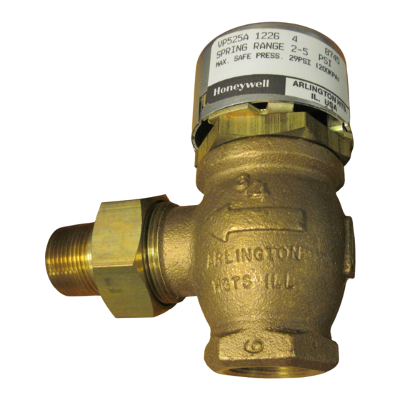
This normally-open, single-seated, straight-through,
pneumatic valve provides two-position or proportional control
of two-pipe hot water or steam systems.
The valve can be installed in any position. The direction of
flow must be in the same direction as the arrow cast on the
valve body.
Refer to Fig. 1 for dimensions to determine the space required
for proper installation. Be sure to allow enough clearance
around the actuator top for servicing after installation.
1-1/2
(38)
1
2-1/4 DIAMETER (57)
A
B
E
D
1 1-1/2 in. (38 mm) MINIMUM CLEARANCE TO REMOVE
ACTUATOR. 2 1/2 in. (63 mm) MINIMUM CLEARANCE
TO FACILITATE STRAIGHT ON TUBING CONNECTION.
IF CLEARANCE IS LESS THAN 2 1/2 in. (63 mm)
USE AN ELBOW.
M16449A
® U.S. Registered Trademark
Copyright © 2002 Honeywell International Inc.
All Rights Reserved
Pneumatic Radiator Valve
AIR CONNECTION
FOR1/4 IN. (6 mm)
O.D. PLASTIC TUBING
COVER FASTENER
C
BODY STYLE
STRAIGHT THRU œ
MALE UNION OUTLET
ANGLE œ MALE
UNION OUTLET
Fig. 1. VP525 threaded union body dimensions in in. (mm).
INSTALLATION INSTRUCTIONS
SPECIFICATIONS
Body Pressure Rating: 150 psi (1034 kPa) maximum.
Controlled Medium Temperature (maximum):
VP525A: 180°F (82°C) maximum.
VP525C: 240°F (116°C) maximum.
Maximum allowable difference (alternating hot and cold
water): 140°F (78K).
Maximum Safe Air Pressure: 30 psi (207 kPa).
Maximum Differential Pressure for Quiet Service:
Water: 20 psi (138 kPa).
Steam (VP525C): 10 psi (69 kPa).
Close Off Ratings:
VP525A: See Fig. 2.
VP525C: See Fig. 3.
1-1/2
(38) 1
2-1/4 DIAMETER (57)
A
B
D
A
SIZE NPT
B
3-1/2 (90) 1-3/8 (35) 2-1/2 (63) 1-3/8 (35)
1/2
3-1/2 (90) 1-3/8 (35) 3
3/4
1/2
3-1/4 (83) 1
(25) 2-5/8 (66) 1-1/8 (29)
3-1/8 (80) 1
(25) 3
3/4
VP525A,C
AIR CONNECTION
FOR1/4 IN. (6 mm)
O.D. PLASTIC TUBING
COVER FASTENER
C
C
D
E
3/4 (19)
(76) 1-5/8 (41) 1-1/8 (29)
(76) 1-1/4 (32)
95-5544EF-1
Publicité
Table des Matières

Sommaire des Matières pour Honeywell VP525A
- Page 1 ANGLE œ MALE USE AN ELBOW. UNION OUTLET 3-1/8 (80) 1 (25) 3 (76) 1-1/4 (32) M16449A Fig. 1. VP525 threaded union body dimensions in in. (mm). ® U.S. Registered Trademark Copyright © 2002 Honeywell International Inc. All Rights Reserved 95-5544EF-1...
- Page 2 (124) Fig. 4. Threaded union body connections. (103) (138) (117) (152) (131) (165) (179) (145) (159) (193) (172) (207) (138) (276) (414) (552) (689) (827) (965) CLOSE OFF DIFFERENTIAL PRESSURE RATINGS PSI (kPa) C7713A Fig. 2. VP525A close-off ratings. 95-5544EF–1...
-
Page 3: Typical Operation
VP525A,C PNEUMATIC RADIATOR VALVE EXCESS DOPE 2 THREADS CLEAN – PIPE SIZE EFFECTIVE LENGTH MAY BLOCK DISC MODERATE OF THREADS OFF VALVE SEAT AMOUNT OF DOPE 1/2 in. 1/2 in. (13 mm) 3/4 in. 9/16 in. (14 mm) LOOSE CHIPS RIGHT –... - Page 4 Automation and Control Solutions Honeywell International Inc. Honeywell Limited-Honeywell Limitée 1985 Douglas Drive North 35 Dynamic Drive Golden Valley, MN 55422 Scarborough, Ontario M1V 4Z9 Printed in U.S.A. on recycled 95-5544EF–1 B.B. Rev. 12-02 www.honeywell.com paper containing at least 10%...
-
Page 5: Vanne Pneumatique Pour Radiateur
à vapeur ou à eau chaude à Température maximale du fluide à régler : deux canalisations. VP525A : 82 °C (180 °F). VP525C : 116 °C (240 °F). Cet appareil peut être installé dans n'importe quelle position. - Page 6 VANNE PNEUMATIQUE POUR RADIATEUR VP525A ET C INSTALLATION GAMME DU RESSORT PRESSION DE FERMETURE DE LA VP525C D'ACTIONNEUR SOUS PRESSION MAXIMALE DU SYSTÊME EN kPa (PSI) Choix du ressort de l'actionneur Les vannes VP525C de la série 2 sont munies d'un ressort de rappel orange (3-10 psi).
-
Page 7: Fonctionnement Typique
VANNE PNEUMATIQUE POUR RADIATEUR VP525A ET C UNE TROP GRANDE 2 FILETS PROPRES – TAILLE LONGUEUR DE QUANTITÉ DE MASTIC QUANTITÉ SUFFISANTE DU TUYAU FILETAGE EFFICACE RISQUE D'OBSTRUER DE MASTIC LE SIÊGE DE VANNE 1/2 po 13 mm (1/2 po) - Page 8 By using this Honeywell literature, you agree that Honeywell will have no liability for any damages arising out of your use or modification to, the literature. You will defend and indemnify Honeywell, its affiliates and subsidiaries, from and against any liability, cost, or damages, including attorneys’ fees, arising out of, or resulting from, any modification to the literature by you.


