Table des Matières
Publicité
Les langues disponibles
Les langues disponibles
Liens rapides
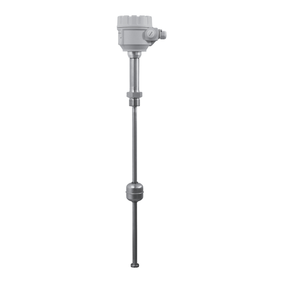
NIVOTRACK
M-500/600, M-500/600 Ex
Émetteur magnétostrictif de niveau à 2 fils
Fabricant:
NIVELCO Process Control Co.
H-1043 Budapest, Dugonics u. 11.
Tél.: (36-1) 889-0100
Fax: (36-1) 889-0200
Courriel: sales
@nivelco.com
www.nivelco.com
♦
ATEX0012X ♦ mba5052i0600p_06
FM16CA0037X ♦ FM16US0068X ♦ IEC Ex BKI 12.0002
♦ 1 / 36
BKI16
Publicité
Table des Matières

Sommaire des Matières pour Nivelco NIVOTRACK M-500
- Page 1 NIVOTRACK M-500/600, M-500/600 Ex Émetteur magnétostrictif de niveau à 2 fils Fabricant: NIVELCO Process Control Co. H-1043 Budapest, Dugonics u. 11. Tél.: (36-1) 889-0100 Fax: (36-1) 889-0200 Courriel: sales @nivelco.com www.nivelco.com ♦ ATEX0012X ♦ mba5052i0600p_06 FM16CA0037X ♦ FM16US0068X ♦ IEC Ex BKI 12.0002 ♦...
- Page 2 CONCEPT DE BASE DE MESURE AVEC NIVOTRACK 100%, 20 mA (P11) Échelle de mesure programmée 0%, 4 mA (P10) NIVEAU = L – DIST = P04 2 / 36 mba5052i0600p_06 ♦ BKI16ATEX0012X ♦ IEC Ex BKI 12.0002♦ FM16US0068X♦ FM16CA0037X...
-
Page 3: Table Des Matières
TABLE OF CONTENTS ROGRAMMABLE FEATURES DESCRIPTION 1. INTRODUCTION..................5 5.3. P ......... 24 2. CODIFICATION ..................6 5.3.1. Basic measurement settings ..............24 5.3.1.1 Units ..................... 24 IMENSIONS 2.1. D ..................8 5.3.1.2 PV mode ..................24 3. DONNÉES TECHNIQUES..............10 5.3.1.3 Damping time................ - Page 4 4 / 36 mba5052i0600p_06 ♦ BKI16ATEX0012X ♦ IEC Ex BKI 12.0002♦ FM16US0068X♦ FM16CA0037X...
-
Page 5: Introduction
1. INTRODUCTION Application Le principe de fonctionnement La série NIVOTRACK M-500, qui fonctionne sur le principe magnétostrictif, L’émetteur magnétostrictif utilise la caractéristique particulière d’un fil offre une mesure de niveau de haute précision pour des réservoirs de magnétostrictif tout au long de l’intérieur d’une sonde rigide ou flexible. Le fil stockage. -
Page 6: Codification
2. CODIFICATION NIVOTRACK – – ONDE ODE LONGEUR OÎTIER UISSANCE ÉSOLUTION RACCORD DE PROCÉDÉ NOMINALE Émetteur seul Tube 1” BSP Aluminium 4 à 20 mA / 0.1 mm Émetteur + Afficheur Tube 2” BSP Plastique 0.1 m 4 à 20 mA / 1 mm Tube 1”... - Page 7 CCESSOIRES À COMMANDER LANGES : M F T – – IMENSION ONCEPTION ORMES MATÉRIAU RESSION INTERNE DIN ANSI DIN / Acier au carbone DN 65 2½” PN 16 / 150 psi 1” BSP DIN / 1.4571 DN 80 3” PN 25 / 300 psi 2”...
-
Page 8: Dimensions
2.1. D IMENSIONS UBE ÉMETTEUR RIGIDE UBE ÉMETTEUR FLEXIBLE VEC RACCORD DE PROCÉDÉ FILETÉ VEC RACCORD DE PROCÉDÉ À MANCHON COULISSANT M A … M C M D … M G M K… M N… Position "A" Position " " B Posiotin "A"... - Page 9 UBE ÉMETTEUR RIGIDE UBE ÉMETTEUR RIGIDE PLASTIFIÉ INI TUBE ÉMETTEUR RIGIDE ANS RACCORD DE PROCÉDÉ ANS RACCORD DE PROCÉDÉ AVEC RACCORD DE PROCÉDÉ FILETÉ MTU… MBU… MEU… MGU… … MC Posiotion "A" Posiotion " " B Posiotion "A" Posit ion"A" max.
-
Page 10: Données Techniques
3. DONNÉES TECHNIQUES IGIDE UBE FLEXIBLE UBE RIGIDE PLASTIFIÉ TYPE M A..., M C…, M D..., M K…, MEU…, M G…, MTU…, MBU…, MM …, MC …, M N… MGU… Valeurs de procédé mesurées Niveau : Distance : Volume Longueur nominale (L) 0.5 m …... -
Page 11: Données Sur Les Mensurations (Msz En 60770-1:2011, Msz En 61298-1:2009, Msz En 61298-3:2009)
3.1. D ONNÉES SUR LES MENSURATIONS (MSZ EN 60770-1:2011, MSZ EN 61298-1:2009, MSZ EN 61298-3:2009) Résolution 1 mm 0.1 mm (l’affichage et les valeurs transmises sur la ligne HART) Le plus grand entre ± 2 mm ou ± 0.02 % F.S. Le plus grand entre ±... -
Page 12: Données Spéciaux Pour Modèles Certifiés Ex
3.2. D ONNÉES SPÉCIAUX POUR MODÈLES CERTIFIÉS EX -5/7 -5Ex -5/7 -CEx -5/7 -AEx -5/7 -6Ex TYPE -5/7 -7Ex -5/7 -Dex -5/7 -BEx -5/7 -8Ex II 1 G Ex ia IIB T6…T5 Ga II 1/2 G Ex d ia IIB T6…T5 Ga/Gb II 2 G Ex d IIB T6…T5 Gb ATEX 0.5 …... -
Page 13: Accessories
3.3. A CCESSORIES Pour les types M K et M N seulement Manuel de programmation et d’installation 1 x poids Carte de garantie 1 x écrou M 10 Déclaration de conformité 1 x rondelle à ressort M 10 Presse-étoupe à 2 pièces (M 20 x 1,5) 1 x rondelle M 10 Joint d’étanchéité... -
Page 14: Classes Et Limites De Température
3.5. C LASSES ET LIMITES DE TEMPÉRATURE IMITES INFÉRIEURES DE TEMPÉRATURE YPE DE PROTECTION d ia - 40 °C - 40 °C - 40 °C -..., -... - 25 °C - 25 °C - 25 °C -…, -…, MC -…, -…... -
Page 15: Installation
Ces effets peuvent être réduits chez les sondes rigides avec l’utilisation d’un tuyau atténuant sur la longueur de la sonde. Consultez un distributeur Nivelco. -
Page 16: Raccordement
Attention! Afin d’éviter d’endommager la sonde, prenez garde de na pas l’entortiller lorsque vous l’installez ou la retirez. Donc, un soin particulier doit être apporté lorsque le raccordement du procédé est vissé ou dévissé de la bride. La meilleure façon est de retenir la sonde avec un outil approprié jusqu’à... -
Page 17: Raccordement Des Unités Certifiées Ex
4.2.1. Raccordement des unités certifiées Ex 200mV MultiCONT Ex power supply 250 Ohm HART Avec HART Normal Avec MULTICONT 4.2.2. Raccordement des unités à doubles compartiments (boîtier XP) Le compartiment de côté du boîtier à deux compartiments (M -F, M -G, M -H) contiens les bornes pour raccorder l’unité... -
Page 18: Programming
If the transmitter is left in Programming Mode by mistake, it will automatically return to Measurement Mode after 30 minutes and modifications will be unsaved. FACTORY SETTINGS The NIVOTRACK M-500/600 type transmitters will be delivered with the following Factory default values: Measurement mode: level (LEV). Displayed value shows level. -
Page 19: The Sap-300 Display Unit
MODULE The SAP-300 is a 64x128 dot-matrix LCD display which can be plugged into the transmitter. (Universal – usable in other NIVELCO devices as well – provided that the system software supports SAP-300.) Warning! The SAP-300 module is based on LCD technology, so please make sure it is not exposed to permanent heat or direct sunlight, in order to avoid damage of the display unit. - Page 20 A, Calculated value of the output current. After the dimension, the mode of current output is indicated by inverse inscription: Manual mode (see: chapter 5.3.2.1 ) HART address is not 0, so output current has become overwritten to 4mA (see: chapter 5.3.2.1) Analogue transmission reacts to a programmed failure condition if an upper or lower fault current is programmed (see: chapter 5.3.2.4 ) B, Output range (4…20mA) indicated in a bargraph.
- Page 21 Information displays: Press button to cycle between the information displays. L:2.345m 1. The general information display (DEV. INFO): overall running time (OV. RUN TIME), run time after power on (RUN TIME), type of interface (INTERFACE), relay (RELAY) and logger (LOGGER) indication.
-
Page 22: Programming With The Sap-300 Display Unit
5.2. P SAP-300 ROGRAMMING WITH THE DISPLAY UNIT When entering the menu the instrument makes a copy of the actual parameters, all changes are done to this duplicated parameter set. During programming the instrument keeps measuring and transmitting with the current (and intact) parameter set. After exiting the menu the instrument replaces the original parameters with the new parameter set and will measure according the new parameters. -
Page 23: Menu Structure
Dialog window The system sends messages or warnings using dialog windows. These usually can be acknowledged by pressing the button or the user can choose between two options (usually YES or NO) by pressing buttons. In some cases to correct an error one of the parameters has to be changed. Edit window An edit window is used for modifying a numeric parameter value. -
Page 24: Rogrammable Features Description
5.3. P ROGRAMMABLE FEATURES DESCRIPTION 5.3.1. Basic measurement settings 5.3.1.1 Units Default measuring unit: Parameter: P00:c, where a: 0, 1. Default value: Menu path: BASIC SETUP / UNITS/ENGINEERING SYSTEM Description: This should be configured as the first step of the programming. Here you can choose the default unit system: European unit system Anglo-Saxon unit system... -
Page 25: Damping Time
5.3.1.3 Damping time Parameter: Default value: 0 sec Menu path: BASIC SETUP / DAMPING TIME Description: Damping time is used to damp the unwanted fluctuations of the output and display. If the measured value changes rapidly the new value will settle with 1% accuracy after this set time. -
Page 26: Output Current Value 20Ma
5.3.2.3 Output current value 20mA Parameter: Default value: Menu path: OUTPUT SETUP / ANALOG OUTPUT / 20mA VALUE Active measurement range (mm) Description: Measured value assigned to 20mA. The transmitted value is in accordance to the primary value (PV) (P01:a). Assignment can be done that the change in measured value and the change in the output value are the same (normal), or opposite directional (inverse operation). -
Page 27: Digital Output
5.3.3. Digital Output 5.3.3.1 HART polling address (if there is a HART option in the device) Parameter: Default value: Menu path: OUTPUT SETUP / SERIAL OUTPUT / ADDRESS Description: HART polling address (only HART capable types) The polling address can be set between 0 and 15. For a single instrument the polling address is 0 and the output is 4...20mA (analogue output). -
Page 28: Calculation Mode
5.3.4.2 Calculation mode Parameter: P47:a, where a: 0,1. Default value: Menu path: CALCULATION / V/M CALC. MODE Description: Calculation of the volume and mass can be performed with two ways: TANK FUNCTION/SHAPE – volume and mass calculation with a tank shape formula. -
Page 29: Tank Dimensions
5.3.4.5 Tank dimensions Parameter: P41- P45 Default value: Menu path: CALCULATION / V/M CALC. MODE / TANK FUNCTION/SHAPE Description: DIM1 (P41) DIM2 (P42) DIM3 (P43) DIM4 (P44) DIM5 (P45) Standing cylindrical tank with Standing cylindrical tank with Standing rectangular tank with hemispherical bottom a = 0 conical bottom a = 1 ;... -
Page 30: Volume And Mass Table (Vmt)
5.3.4.6 Volume and Mass Table (VMT) Parameter: Menu path: CALCULATION / V/M CALC. MODE / V/M TABLE Description: View/Edit table Add item Delete item If none of the formulas match perfectly to the characteristics of the needed tank, there is a possibility to use table calculation mode. -
Page 31: Service Functions
5.3.5. Service functions 5.3.5.1 Security codes User codes Menu path: SERVICE / SECURITY / USER LOCK Description: Setting or unlocking the user security code. The instrument can be protected against unauthorized programming with a 4 digit PIN (Personal Identification Number) code. If either of the digits differs from 0 the code is active. -
Page 32: Distance Simulation
5.3.5.3 Distance simulation This function facilitates the user to be able to check the calculations (tank formula, table), outputs, and the additional processing instruments connected to the output. NIVOTRACK transmitters can perform simulation on the value of a constant or a variable. To start simulation the instrument must return to Measurement mode. -
Page 33: Load Default Values
5.3.5.4 Load default values Menu path: SERVICE / DEFAULTS / LOAD DEFAULT Description: This command loads all default values of the instrument. After loading the default values the parameters can freely be changed, the effect of the changes does not affect the measurement until the user exits programming mode and returns to measurement mode. -
Page 34: Error Codes
6. ERROR CODES ESSAGE ON THE SCREEN RROR ESCRIPTION ROCEDURE MEMORY ERROR Memory error in the electronics Contact the service! NO INPUT SIGNAL Probe error Contact the service! EE COM. ERROR Hardware error (EEPROM communication error) Contact the service! MATH. OVERLOAD Display overflow Check the programming! SIGNAL IN N.D.B. -
Page 35: Menu Map
7. MENU MAP FM16CA0037X ♦ FM16US0068X ♦ IEC Ex BKI 12.0002 ♦ BKI16ATEX0012X ♦ mba5052i0600p_06 ♦ 35 / 36... - Page 36 July 2016 NIVELCO reserves the right to change technical data without notice! 36 / 36 mba5052i0600p_06 ♦ BKI16ATEX0012X ♦ IEC Ex BKI 12.0002♦ FM16US0068X♦ FM16CA0037X...