Table des Matières
Publicité
Les langues disponibles
Les langues disponibles
Liens rapides
Publicité
Table des Matières

Manuels Connexes pour Multimetrix CM600


Sommaire des Matières pour Multimetrix CM600
- Page 1 MULTIMETER MESSZANGE MULTIMETRO MULTIMERICA CM600 CM610 CM625...
- Page 2 Français .....................4 English ....................9 Deutsch ....................15 Italiano....................22 Español ....................28 CM600 CM610 CM600 CM610...
-
Page 3: Conditions Generales De Garantie Et De Securite
CONDITIONS GENERALES DE GARANTIE ET DE SECURITE 1. PRECAUTIONS D’EMPLOI Lisez les instructions de sécurité ci-dessous avant toute utilisation de l’appareil, afin d’éviter les accidents corporels, tels que brûlures et chocs électriques. Suivez impérativement les indications précédées du symbole 1.1 DEFINITION DES CATEGORIES D’INSTALLATION (cf. -
Page 4: Recommandations Diverses De Securite
1.5 RECOMMANDATIONS DIVERSES DE SECURITE Pour les appareils des catégories d’installation I et II, ne travaillez jamais sur des équipements pouvant générer des pics de tension (moteurs, etc.). Pour la mesure en gamme manuelle, commencez toujours par la gamme maximale. Sélectionnez ensuite la gamme la plus appropriée. -
Page 5: Utilisation
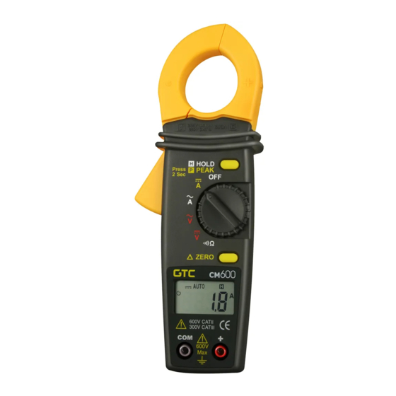
Repère Fonction Borne négative noire (-) COM Afficheur à cristaux liquides : - CM600 / CM610 : 3 digits ½ (1999 points) - CM625 : 4 digits (4369 points) ‘----‘ : dépassement de capacité en mesure de courant et tension Sélecteur rotatif de fonction... -
Page 6: Mesure De Tension
Lire la valeur du courant une fois celle-ci stabilisée. L’affichage de « ----- » indique un dépassement de capacité. - CM600 et CM610 : pour afficher les valeurs max., voir §. 7.9. - CM600 et CM610 : pour mémoriser la valeur lue, voir §. 7.10. -
Page 7: Mesure De Resistance
à contrôler. Le signal sonore sera audible lorsque le circuit à contrôler est continu ou de résistance inférieure à 60 Ω ± 20 Ω (CM600 et CM610) et 50 Ω ± 25 Ω (CM625). Positionner le sélecteur sur OFF. -
Page 8: Accessoires Et Options
CM600 & CM610 : mesure maximale (MAX) CM625 : mémorisation de mesure (Data Hold) Indication usure piles Symbole piles faibles Fréquence CM600 et CM610 : environ 3 x par s d’échantillonnage CM625 : environ 2 x par s Ouverture maximale 30 mm des mâchoires Utilisation 0 à... -
Page 9: Precautions During Use
GENERAL SAFETY AND GUARANTEE CONDITIONS 1. PRECAUTIONS DURING USE Please read the safety instructions below before using the instrument to avoid any accidental injuries, such as burns or electric shocks. You must observe the instructions preceded by the symbol 1.1 DEFINITION OF THE INSTALLATION CATEGORIES (Cf. -
Page 10: Unpacking And Repacking
1.5 OTHER SAFETY RECOMMENDATIONS For instruments of installation categories I and II, never work on equipment that could generate voltage spikes (motors, etc.). When measuring in the manual range, always start with the maximum range and then select the most appropriate range. First of all connect the black contact point and then the red one. - Page 11 6.1 THE FRONT FACE Function Black negative COM terminal (-) Liquid crystal display: - CM600 / CM610: 3 ½ digits (1999 points) - CM625: 4 digits (4369 points) ‘----‘: current and voltage measurements exceed the range Function rotary selector switch...
- Page 12 If “-----“ is displayed, the capacity has been exceeded. - CM600 and CM610: to display the maximum value, see §. 7.9. - CM625: to store the maximum reading, see §. 7.10. Set the selector to OFF.
-
Page 13: Continuity Test
The buzzer sounds when the circuit to be checked is DC or has a resistance of less than 60 Ω ± 20 Ω (CM600 & CM610) or 50 Ω ± 25 Ω (CM625). Set the selector to OFF. -
Page 14: Accessories And Options
CM625: measurement storage (Data Hold) Battery low charge Low battery symbol indication Sampling frequency CM600 & CM610: approx. 3 x per sec. CM625: approx. twice per sec. Maximum opening of 30 mm jaws 0 to 50°C (32°F - 122°F). RH < 80%,... -
Page 15: Vorsichtsmassnahmen Beim Gebrauch
ALLGEMEINE GARANTIEBEDINGUNGEN UND SICHERHEITSHINWEISE 1. VORSICHTSMASSNAHMEN BEIM GEBRAUCH Lesen Sie die folgenden Sicherheitsanweisungen vor dem Gebrauch des Gerätes, um Verletzungen wie Verbrennungen und Stromschläge zu vermeiden. Alle mit diesem Symbol gekennzeichneten Anweisungen müssen unbedingt beachtet werden. 1.1 DEFINITION DER INSTALLATIONSKLASSEN (siehe IEC 664-1) KAT. - Page 16 1.5 VERSCHIEDENE SICHERHEITSHINWEISE Geräte der Installationsklassen I und II dürfen niemals an Einrichtungen verwendet werden, welche Spannungsspitzen hervorrufen könnten (Motoren, usw.). Bei Messungen im manuellen Bereich sollten Sie immer mit dem höchsten Bereich beginnen und anschließend den passenden Bereich auswählen. Schließen Sie zuerst die schwarze Prüfspitze, dann die rote Prüfspitze an.
-
Page 17: Die Rückseite
6.1 DIE VORDERSEITE Abb. Funktion Negative schwarze Anschlussklemme (-) COM LCD - Anzeigegerät: - CM600 & CM610: 3 Ziffern ½ (1.999 Punkte) - CM625: 4 Ziffern (4.369 Punkte) ‘----‘: Bereichsüberschreitung bei der Strom- und Spannungsmessung Drehbarer Funktionsauswahlknopf OFF: ausgeschaltetes Universalmessgerät : Wechselstrom (CM600 &... - Page 18 Bitte lesen Sie vor der Verwendung aufmerksam die Sicherheitshinweise durch. Automatische Messbereiche: CM600 & CM610: 200 mVDC bis 600 VDC (5 Bereiche) und 2 VAC bis 600 VAC (4 Bereiche). CM625: 4 VDC bis 600 VDC (4 Bereiche) und 4 VAC bis 600 VAC (4 Bereiche).
- Page 19 7.5 MESSUNG DES WECHSELSTROMES Automatische Messbereiche: CM600 & CM610: 200 AAC oder 600 AAC (2 Bereiche). CM625: 40 AAC oder 400 AAC (2 Bereiche). 1. Bitte stellen Sie den Auswahlknopf (Abb. 3) auf Die Symbole (Abb. 15 und 21) werden angezeigt.
-
Page 20: Zubehör Und Optionen
7.9 FUNKTION MAX (ANZEIGE DES HÖCHSTWERTES - CM600 & CM610) Bitte stellen Sie den Auswahlknopf auf oder und betätigen Sie nun die Taste MAX. Das Symbol wird angezeigt (Abb. 18). Führen Sie nun bitte die Messung durch. Die Höchstmessung wird automatisch aktualisiert. - Page 21 CM625: Speicherung der Messung (Data Hold) Angabe des Symbol Batterieschwäche Batterieverbrauchs Stichprobenfrequenz CM600 & CM610: etwa 3 Mal pro Sek. CM625: etwa 2 Mal pro Sek. Max. Oeffnung der 30 mm Zangenbacken Verwendung 0 bis 50°C (32°F - 122°F) RH < 80%,...
-
Page 22: Avvertenze Per L'uso
CONDIZIONI GENERALI DI GARANZIA E SICUREZZA 1. AVVERTENZE PER L’USO Leggere le seguenti istruzioni di sicurezza prima di qualsiasi uso dell’apparecchio, per evitare incidenti fisici quali bruciature e scosse elettriche. Le disposizioni precedute dal simbolo vanno rigorosamente rispettate. 1.1 DEFINIZIONE DELLE CATEGORIE DI IMPIANTO (cfr. -
Page 23: Disimballaggio E Reimballaggio
1.5 RACCOMANDAZIONI NON DI SICUREZZA Per gli apparecchi delle categorie di impianti I e II, non operare mai su attrezzature che possono generare picchi di tensione (motori, ecc.). Per la misurazione manuale, partire sempre dalla gamma massima. Successivamente selezionare gamma più... -
Page 24: Lato Anteriore
Fig. Funzione Terminale negativo nero (-) COM Visore a cristalli liquidi : - CM600 & CM610 : 3 cifre ½ (1999 punti) - CM625 : 4 cifre (4369 punti) ‘----‘ : superamento capacità nella misurazione di corrente e tensione. Selettore ruotante di funzioni... - Page 25 Leggere le disposizioni di sicurezza prima dell’uso. Gamme di misurazioni automatiche : CM600 & CM610 : 200 mVDC a 600 VDC (5 gamme) e 2 VAC a 600 VAC (4 gamme). CM625 : 4 VDC a 600 VDC (4 gamme) e 4 VAC a 600 VAC (4 gamme).
-
Page 26: Test Di Continuità
+ (fig. 10) e applicare i puntali di tasto sul circuito da verificare. Il segnale sonoro sarà udibile quando il circuito da controllare è continuo o con resistenza inferiore a 60 Ω ± 20 Ω (CM600 & CM610) e 50 Ω ± 25 Ω (CM625). Posizionare il selettore su OFF. -
Page 27: Sostituzione Delle Pile
CM625 : Memorizzazione della mis. (Data Hold) Indicazione usura pile Simbolo di pile che si stanno scaricando Frequenza di CM600 & CM610 : circa 3 volte al campionatura secondo CM625 : circa 2 volte al secondo Apertura massimale 30 mm... -
Page 28: Precauciones De Uso
CONDICIONES GENERALES DE GARANTÍA Y DE SEGURIDAD 1. PRECAUCIONES DE USO Lea las siguientes instrucciones de seguridad antes de utilizar el aparato, con el fin de evitar los accidentes corporales, como quemaduras y electrocuciones. Respete obligatoriamente las indicaciones precedidas del símbolo 1.1 DEFINICION DE LAS CATEGORIAS DE INSTALACIÓN (ver CEI 664-1) -
Page 29: Desembalaje Y Re-Embalaje
1.5 RECOMENDACIONES DIVERSAS DE SEGURIDAD Para los aparatos de las categorías de instalación I y II, no trabaje nunca sobre equipamientos que puedan generar picos de tensión (motores, etc.). Para la medición en gama manual, empiece siempre por la gama máxima. Seleccione luego la gama más apropiada. Conecte primero la punta de toque negra, luego la roja. - Page 30 Marca. Función Borne negativo negro (-) COM Pantalla de cristales líquidos: - CM600 & CM610: 3 dígitos ½ (1999 puntos) - CM625: 4 dígitos (4369 puntos) ‘----‘: superación de la capacidad de medición de corriente y tensión Conmutador de funciones.
-
Page 31: Medición De Tensión
Lea las recomendaciones de seguridad antes de utilizar. Gamas de medición automáticas: CM600 & CM610: 200 mVDC a 600 VDC (5 gamas) y 2 VAC a 600 VAC (4 gamas) CM625: 4 VDC a 600 VDC (4 gamas) y 4 VAC a 600 VAC (4 gamas) Posicionar el selector (marca 3) sobre el símbolo tensión. -
Page 32: Medición De Resistencia
- CM600 & CM610: para memorizar el valor leído, ver §. 7.10. Abrir la pinza, liberar el conductor y posicionar el selector sobre OFF. 7.6 MEDICIÓN DE RESISTENCIA Lea las recomendaciones de seguridad antes de utilizar. El circuito estará obligatoriamente fuera de tensión. -
Page 33: Accesorios Y Opciones
Medición de los CM600, CM610 & CM625: Tensiones valores continuas, tensiones alternas, corriente alterna, resistencia, test de continuidad CM600 & CM610: test de diodos CM625:Corriente continua Método de mediciones CM610 & CM625 :True RMS AC (tensión eficaz verdadera) Pantalla CM600 & CM610: 2.000 puntos CM625: 4.369 puntos... - Page 34 CM600 & CM610 CM625 Range (A) 200/600 40/400 50 → 500 Hz 50 → 400 Hz Resolution (A) 0.1/1.0 0.01/0.1 Accuracy (±%) 1.9 + 10 dgt ±1.5 + 10 dgt (200 A) (40 A) 1.9 + 5 dgt 1.5 + 5 dgt...
- Page 35 07 - 2004 Code 691036A00 - Ed. 2 Deutschland - Straßburger Str. 34 - 77694 KEHL /RHEIN - Tél : (07851) 99 26-0 - Fax : (07851) 99 26-60 España - C/ Roger de Flor N°293 - Planta 1 - 08025 BARCELONA - Tél : (93) 459 08 11 - Fax : (93) 459 14 43 Italia - Via Sant’...