Table des Matières
Publicité
Les langues disponibles
Les langues disponibles
Liens rapides
FAILURE TO READ AND FOLLOW ALL INSTRUCTIONS CAREFULLY BEFORE
INSTALLING OR OPERATING THIS CONTROL COULD CAUSE PERSONAL
INJURY AND/OR PROPERTY DAMAGE.
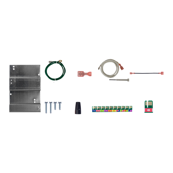
1- Mounting Bracket
SPECIFICATIONS
ELECTRICAL RATINGS:
Input Voltage: 18 to 30 VAC, 60 Hz
Current: 0.2A + MV + PV @ 25
Relay Contact Ratings:
Pilot Valve Relay: 1.5A @ 25 VAC, 60 Hz
Main Valve Relay: 1.5A @ 25 VAC, 60 Hz
Spark Output:
Gap: 0.1" - 0.2", 15 kV, 25Hz
Max cable length 3 ft (0.9 m)
Flame Current Requirements:
Minimum current to insure flame detection: 2 µA DC*
Maximum current for non-detection: 0.2 µA DC
Maximum allowable leakage resistance: 100 M ohms
* Measured with a DC microammeter in series with the
flame probe lead
OPERATING TEMPERATURE RANGE:
-40° to 175°F (-40° to 80°C)
HUMIDITY RANGE:
To 95% relative humidity (non-condensing)
AGENCY APPROVALS:
CSA USA / Canada
GASES APPROVED: Natural, Manufactured, Mixed,
Liquid Petroleum, and LP Gas Air Mixtures
1- 1/4" insulated
1- Green
Female spade
Ground Wire
connector
Assembly
2- Wire nuts
4- Mounting
Screws
C
O
white-rodgers.com
emersonclimate.com
50D50-801
Proven Pilot Spark Control
INSTALLATION INSTRUCTIONS
1 - Flame sensor
+ Wire Assembly
10- Program Keys
CAUTION
!
Risk of Electric Shock. Disconnect
electric power to system until
installation is complete. Do not
use on circuit exceeding specified
voltage. Higher voltage will
damage control and could cause
shock or fire hazard.
This control is not intended for
use in locations where it may
come in contact with water.
May cause flame rollout. Shut off
main gas to heating system until
installation is complete.
PARTS INCLUDED
3- 1/4" to 3/16"
0115-0269
Harnesses
1- Lennox Program
Key to Use
PART NO. 37-7588C
1629
Publicité
Table des Matières

Sommaire des Matières pour Emerson White-Rodgers 50D50-801
- Page 1 50D50-801 Proven Pilot Spark Control INSTALLATION INSTRUCTIONS FAILURE TO READ AND FOLLOW ALL INSTRUCTIONS CAREFULLY BEFORE INSTALLING OR OPERATING THIS CONTROL COULD CAUSE PERSONAL INJURY AND/OR PROPERTY DAMAGE. PARTS INCLUDED 1- 1/4" insulated 3- 1/4" to 3/16" 1 - Flame sensor 1- Green Female spade + Wire Assembly...
-
Page 2: Mounting Orientation
INSTALLATION Table 2 Mounting and Wiring Lennox G23 & G26-75 Figure 1 Mounting Holes Use Screws Remove the existing NOTE mounting bracket and C-C1 2x 1/2 in. install New Mounting Bracket All wiring should be installed according to local and national Install 50D50-801 Control D-D1 2x 3/4 in. - Page 3 WIRING Replacing JCI Ignition Controls 69J3601 & 74H2601 50D50-801 3/16” 3/16” 3/16” 1/4” 1/4” 1/4” 1/4” 1/4” Spade Spade Spade Spade Spade Spade Spade Spade 1/4” FLAME Spade For G23/G26 units: connect combustion air pressure switch For G20/G20R units: connect Blocked vent switch Flame Sensor...
-
Page 4: Typical Operation
Control failure replace control. Outputs Thermostat “TH” Pilot Valve Ignitor Pilot Flame Sensed Main Valve Main Flame Sensed White-Rodgers is a business of Emerson Electric Co. The Emerson logo is a white-rodgers.com trademark and service mark emersonclimate.com of Emerson Electric Co. -
Page 5: Pièces Incluses
50D50-801 Régulateur d’étincelle de pilote éprouvé DIRECTIVES D’INSTALLATION LE FAIT DE NE PAS LIRE ET DE NE PAS RESPECTER SOIGNEUSEMENT TOUTES LES DIRECTIVES AVANT L’INSTALLATION OU L’UTILISATION DE CE RÉGULATEUR PEUT CAUSER DES BLESSURES OU DES DOMMAGES MATÉRIELS. PIÈCES INCLUSES 1 - Connecteur 3 - Faisceau 3/16 po 1 - Ensemble du... -
Page 6: Montage Et Câblage
INSTALLATION Tableau 2 Montage et câblage Lennox G23 et G26-75 Figure 1 Trous de montage Utiliser des vis Retirer la ferrure de montage 1/2 po (1.27 cm) REMARQUE existante et installer la C-C1 nouvelle ferrure de montage Tout le câblage doit être installé conformément aux codes et Installer le régulateur D-D1 3/4 po (1.9 cm) 2x... - Page 7 CÂBLAGE Remplacement des régulateurs d’allumage JCI 69J3601 et 74H2601 50D50-801 É Connecteur Connecteur Connecteur Connecteur Connecteur Connecteur Connecteur Connecteur 3/16 po 3/16 po 3/16 po 1/4 po 1/4 po 1/4 po 1/4 po 1/4 po Connecteur FLAMME 1/4 po Pour les unités G23/G26 : connecter le pressostat d’air de combustion Pour les unités G20/G20R :...
-
Page 8: Fonctionnement Typique
Allumeur Flamme pilote détectée Robinet principal Flamme principale détectée White-Rodgers est une entreprise d’Emerson Electric Co. Le logo d’Emerson est une marque white-rodgers.com de commerce et une marque de emersonclimate.com service d’Emerson Electric Co.


