Publicité
Les langues disponibles
Les langues disponibles
Liens rapides
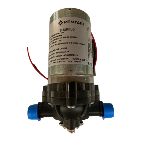
SHURFLO® Industrial Series 2088 Pumps
INSTALLATION & OPERATION MANUAL
SHURflo offers various pumps models for different applications. The information outlined by this manual is general, and not specific to all 2088 series pumps. Be
certain the pumps' materials will be compatible with the fluid being pumped. 2088 series pumps are intended for intermittent or continuous duty when the proper
operating criteria are met. Product Data Sheets outlining specific thermal limits, load, flow curves, and other technical information for a particular model are
available. If unsure of the chemical compatibility with a given elastomer or the motors intended design, please call SHURflo for assistance.
GENERAL CAUTION STATEMENTS
"Intermittent Duty" is defined as; operated and/or frequently started within a period of time that would cause the motor to reach its maximum thermal limits.
Once the maximum thermal limit is obtained, the motor must be allowed to return to ambient temperature before resuming operation.
DO NOT use to pump flammable liquids. Never operate the pump in an explosive environment. Arcing from the motor brushes, switch or excessive heat from
an improperly cycled motor may cause an explosion.
DO NOT assume fluid compatibility. If the fluid is improperly matched to the pumps' elastomers, a leak may occur. Pumps used to transfer hazardous or hot
(max. temperature 170F [76C] Viton™ only) chemicals must be in a vented area to guard against the possibility of injury due to harmful or explosive
liquid/vapors.
DO NOT operate the pump at pressures which cause the motor to exceed the ampere rating indicated on the name plate. Various pump models are equipped
with thermal breakers to interrupt operation due to excessive heat. Once the temperature of the motor is within proper limits it will automatically reset, and
the pump will start operation without warning.
To prevent electrical shock, disconnect power before initiating any work. In the case of pump failure, the motor housing and/or the pumped fluid may carry
high voltage to components normally considered safe.
Improper adjustment of the pressure switch may cause severe overload or premature failure. Refer to SHURflo Service Bulletin #1031 for the adjustment
procedure. Failures due to improper adjustment of the pressure switch will not be covered under the limited warranty.
DO NOT locate the motor near low temperature plastics or combustible materials. The surface temperature of the motor may exceed 250° F [120° C].
Electrical wiring should be performed by a qualified electrician, in accordance with all local electrical codes.
All 115
and 230
pump motors and systems,
VAC
VAC
PRESSURE SWITCH OPERATION
The pressure switch reacts to outlet pressure, and interrupts power at the preset shut-off pressure indicated on the pump label. When outlet pressure drops below a
predetermined limit (typically 15-20 psi. 1-1.4 bar less than the shut-off pressure), the switch will close and the pump will operate until the shut-off (high) pressure is
achieved. The shut-off pressure is set to factory calibrated standards. See the motor label and Product Data Sheet for specific pump specifications.
If the plumbing is restrictive or the flow rate is very low, the pump may re-pressurize the outlet faster than the fluid is being released causing rapid cycling (
2 seconds). If the pump is subjected to rapid cycling during normal operation, or for infrequent periods, damage may occur. Applications which exhibit rapid
WITHIN
cycling should have restrictions in the outlet minimized. If not feasible, consider a SHURflo Accumulator or a SHURflo "bypass" model pump.
BYPASS OPERATION
A bypass pump may be used for applications that normally induce frequent start/stop of the motor, and thereby create a potential for overheating. Models equipped with an
internal bypass are designed to pump at high pressure while at low flow rates. Bypass models equipped with a switch may operate for several seconds even though the outlet side
has been closed off. Contact SHURflo for information regarding bypass pumps.
MOUNTING
The 2088 series pumps are self-priming. Horizontal and vertical prime vary depending on the fluid viscosity and pump configuration.
The pump should be located in an area that is dry and provides adequate ventilation. If mounted within an enclosure, provisions to cool the motor may be necessary.
Heat sinks which attach to the motor are available from SHURflo if increased heat dissipation is necessary.
The pump may be mounted in any position. However, if mounting the pump vertically the pump head should be in the down position so that in the event of a leak,
fluid will not enter the motor. Secure the rubber feet with #8 hardware. DO NOT compress the feet, doing so will reduce their ability to isolate vibration/noise.
PLUMBING
Flexible high pressure tubing compatible with the fluid should be used to connect the inlet/outlet ports. Tubing should be either 3/8" or ½" [10 or 13 mm] I.D., and at least 18 in.
[46 cm] length is suggested to minimize stress on the fitting/ports and reduce noise. Allow for the shortest possible tubing route and avoid sharp bends that may kink over time.
NOTE: Restrictions on the inlet may cause vacuum levels to reach the fluid vapor pressure, causing cavitation, degassing, vapor lock and a loss in performance. Inlet
pressure must not exceed 30 psi. [2.1 bar] maximum.
1/2" Male threaded models: Are intended to be used with SHURflo Swivel Barb Fittings which seal with an internal taper when hand tightened. Standard 1/2" NPT
fittings may be used when tightened to a maximum torque of 3.7 ft.\Lb. (45 in\Lb.) [5 Nm].
NOTE: SHURflo does not recommend the use of metal fittings or rigid pipe to plumb the inlet/outlet ports. Standard plastic male and female threaded fittings can be acquired at
commercial plumbing supply stores. SHURflo also distributes Swivel Barb Fittings, and special fitting through its dealers.
Sealers and Teflon tape may act as lubricant causing cracked housings or stripped threads due to over-tightening. Care should be used when applying sealers. Sealers may enter
the pump inhibiting valve action, causing no prime or no shut-off. A failure due to foreign debris is not covered under warranty. Installation of a 50 mesh strainer is
recommended to prevent foreign debris from entering the pump.
If a check valve is installed in the plumbing, it must have a cracking pressure of no more than 2 psi [.14 bar].
be grounded per local and state electrical codes.
MUST
/OFF
ON
Publicité

Manuels Connexes pour Pentair SHURFLO 2088 Serie


Sommaire des Matières pour Pentair SHURFLO 2088 Serie
- Page 1 SHURFLO® Industrial Series 2088 Pumps INSTALLATION & OPERATION MANUAL SHURflo offers various pumps models for different applications. The information outlined by this manual is general, and not specific to all 2088 series pumps. Be certain the pumps' materials will be compatible with the fluid being pumped. 2088 series pumps are intended for intermittent or continuous duty when the proper operating criteria are met.
- Page 2 All Industrial pumps/products must be flush of any chemicals before *shipping. All warranty considerations are governed by SHURFLO's written Return Policy. Returns are to be shipped postage prepaid to our service center in Elkhart, IN. SHURFLO shall not be liable for freight damage incurred during shipping. Package returns carefully. PENTAIR-SHURFLO, 52748 Park Six Ct., Elkhart, IN 46514.
- Page 3 SHURFLO® Pompes industrielles de la série 2088 Manuel d’installation et d’utilisation ATTENTION GÉNÉRAL MISE EN GARDE : Par « fonctionnement intermittent », on entend le fonctionnement ou le démarrage fréquent dans un délai dans lequel le moteur atteindrait ses limites thermiques maximales. Une fois que la limite thermique maximale est atteinte, il faut permettre au moteur de retourner à...
- Page 4 Pentair Water Belgium bvba, Industriepark Wolfstee, Toekomstlaan 30, B-2200 Herentals, Belgique, +32-14-283500 Tous les logos et marques de commerce Pentair sont la propriété de Pentair, Inc. Tous les autres noms de marque ou de produit sont des marques de commerce ou des marques déposées de leurs détenteurs respectifs.