
Manuels Connexes pour Miller FILTAIR

Sommaire des Matières pour Miller FILTAIR
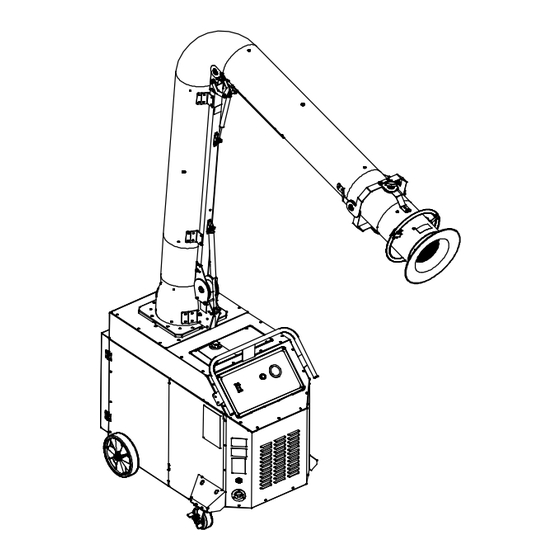
- Page 1 OM-260 545D 2013−10 Processes Multiprocess Welding Description Mobile Weld Fume Extractor FILTAIR Capture 5 Fume Extractor 3 Phase Read And Save These Instructions File: Accessory Visit our website at www.MillerWelds.com...
- Page 2 We know you don’t have time to do it any other way. That’s why when Niels Miller first started building arc welders in 1929, he made sure his products offered long-lasting value and superior quality.
-
Page 3: Table Des Matières
TABLE OF CONTENTS SECTION 1 − SAFETY PRECAUTIONS - READ BEFORE USING ....... . . 1-1. -
Page 5: Section 1 − Safety Precautions - Read Before Using
SECTION 1 − SAFETY PRECAUTIONS - READ BEFORE USING fume 2013−09 Protect yourself and others from injury — read, follow, and save these important safety precautions and operating instructions. 1-1. Symbol Usage DANGER! − Indicates a hazardous situation which, if Indicates special instructions. -
Page 6: Arc Welding And Plasma Cutting Hazards
FALLING EQUIPMENT can injure. FIRE OR EXPLOSION hazard. D Use equipment of adequate capacity to lift and D Do not install or place unit on, over, or near support unit. combustible surfaces. D If using lift forks to move unit, be sure forks are D Do not install unit near flammables. - Page 7 D Do not weld or cut where the atmosphere may contain flammable FUMES AND GASES can be hazardous. dust, gas, or liquid vapors (such as gasoline). D Connect work cable to the work as close to the welding or cutting Welding and cutting produces fumes and gases.
-
Page 8: Additional Symbols For Installation, Operation, And Maintenance
ELECTRIC AND MAGNETIC FIELDS (EMF) NOISE can damage hearing. can affect Implanted Medical Devices. Noise from some processes or equipment can D Wearers of Pacemakers and other Implanted damage hearing. Medical Devices should keep away. D Wear approved ear protection if noise level is D Implanted Medical Device wearers should consult their doctor high. -
Page 9: California Proposition 65 Warnings
D Have the installation regularly checked and maintained. READ INSTRUCTIONS. D Keep high-frequency source doors and panels tightly shut, keep spark gaps at correct setting, and use grounding and shielding to D Read and follow all labels and the Owner’s minimize the possibility of interference. -
Page 10: Section 2 − Mesures De Sécurité −Extraction Des Fumées − À Lire Avant Utilisation
SECTION 2 − MESURES DE SÉCURITÉ − EXTRACTION DES FUMÉES − À LIRE AVANT UTILISATION fume_2013−09_fre Se protéger et protéger les autres contre le risque de blessure — lisez, appliquez et rangez en lieu sûr ces consignes importantes de sécurité et d’utilisation. 2-1. -
Page 11: Dangers Du Soudage À L'arc Et Du Coupage Au Plasma
nettoyants, les consommables, les produits de refroidissement, les Les PIÈCES MOBILES peuvent dégraisseurs, les flux et les métaux. causer des blessures. D L’extracteur de fumées doit être utilisé avec le bras d’extraction, les D S’abstenir de toucher des organes mobiles tels tuyaux, le filtre et les autres composants recommandés par le fabricant. - Page 12 D Les câbles doivent être exempts d’humidité, d’huile et de graisse; D Ne soudez pas ou ne coupez pas des métaux enrobés tels que des protégez−les contre les étincelles et les pièces métalliques métaux galvanisés, contenant du plomb ou de l’acier plaqué au chaudes.
-
Page 13: Dangers Supplémentaires En Relation Avec L'installation, Le Fonctionnement Et La Maintenance
D Avant de souder, retirer toute substance combustible de vos po- D Le couvercle du détendeur doit toujours être en place, sauf lorsque ches telles qu’un allumeur au butane ou des allumettes. la bouteille est utilisée ou qu’elle est reliée pour usage ultérieur. D Une fois le travail achevé, assurez−vous qu’il ne reste aucune D Utiliser les équipements corrects, les bonnes procédures et suffi- trace d’étincelles incandescentes ni de flammes. - Page 14 D Tenir l’équipement (câbles et cordons) à distance des véhicules Les PIÈCES MOBILES peuvent mobiles lors de toute opération en hauteur. causer des blessures. D Suivre les consignes du Manuel des applications pour l’équation D S’abstenir de toucher des organes mobiles tels de levage NIOSH révisée (Publication Nº94–110) lors du levage manuelle de pièces ou équipements lourds.
-
Page 15: Proposition Californienne 65 Avertissements
LE SOUDAGE À L’ARC ET LE RAYONNEMENT HAUTE COUPAGE PLASMA risquent de FRÉQUENCE (H.F.) risque provoquer des interférences. provoquer des interférences. D Le rayonnement haute fréquence (H.F.) peut D L’énergie électromagnétique peut gêner le provoquer des interférences avec les équi- fonctionnement d’appareils électroniques sen- pements de radio−navigation et de com- sibles comme des ordinateurs et des équi-... -
Page 16: Section 3 − Definitions
SECTION 3 − DEFINITIONS 3-1. Additional Safety Symbols And Definitions Keep away from pinch points. Safe110 2012−11 3-2. Miscellaneous Symbols And Definitions Protective Earth Percent (Ground) Amperes Volts Air Filter Input Power Cleaning In Rated Supply Cleaning Required Line Connection Process Voltage Rated Supply... -
Page 17: Section 4 − Specifications
SECTION 4 − SPECIFICATIONS 4-1. Introduction The Capture series of weld fume collectors incorporates a high-volume vacuum system that uses a high efficiency, nanofiber-media cartridge filter to collect airborne weld fume particles. Weld fumes are captured at the source by a unit-mounted extraction arm. The extraction arm uses gas-shock assisted friction joints and flexible tubing to ensure the hood is placed near the source of the fumes. -
Page 18: Extraction Arm Specifications
4-4. Extraction Arm Specifications Model Arm Reach Arm Diameter Weight XD-10 95 lb (43 kg) 10 ft (3 m) 10 in. (254 mm) XD-12 12 ft (3.7 m) 10 in. (254 mm) 105 lb (48 kg) 4-5. Fume Capture Zone The fume capture zone repres- ents the maximum size and shape of the fume withdrawal... -
Page 19: Section 5 − Installation
SECTION 5 − INSTALLATION 5-1. Selecting A Location Do not move or operate unit where it could tip. Do not use this equipment to support personnel, large tools, or other material. Special installation may be re- quired where gasoline or vola- tile liquids are present −... -
Page 20: Tipping
5-2. Tipping Do not move or operate unit where it could tip. Do not move unit with extrac- tion arm extended or unit may tip. Do not move unit by pulling on extraction arm or equip- ment may tip. Use handle on fume extractor to move unit Do not use this equipment to support personnel, large... -
Page 21: Installing Extraction Arm Base Assembly
5-4. Installing Extraction Arm Base Assembly Turn Off and disconnect in- put power. Stabilize fume extractor by locking front wheels (casters). Base Assembly After installing extraction arm on cart, 3/8 in. Screw remove pin so arm moves freely. 3/8 in. Flat Washer Place base assembly on cart. -
Page 22: Connecting To Compressed Air Supply
5-5. Connecting To Compressed Air Supply Shut off air supply before disconnecting or connecting air hose. Wear protective equipment when disconnecting com- pressed air supply. Internal air tank is under pressure and will discharge when air supply is disconnected. Latch filter and close door before starting unit or oper- ating filter cleaning system. -
Page 23: Wiring Input Power Connector (Nema L16-20R)
5-6. Wiring Input Power Connector (NEMA L16-20R) Installation must meet all Na- tional and Local Codes − have only qualified persons make this installation. X Terminal Input Power Cord Select cord according to Section 5-7. Y Terminal 480 V AC, Three-Phase, 20 A, 3P4W Connector (Supplied) 600 V AC, Three-Phase, 30A 3P4W Connector (Supplied) -
Page 24: Connecting Input Power
5-8. Connecting Input Power Input 8 2012−11 / 260 889-B / 261 487-A Installation must meet all National Input Power Conductors (Customer Connect input conductors L1 (X), L2 (Y) and Local Codes − have only quali- Supplied Cord) And L3 (Z) to disconnect device line termi- fied persons make this installation. -
Page 25: Section 6 − Operation
SECTION 6 − OPERATION 6-1. Controls 260 882-B / 261 582-A Only use the fume extractor to ex- tween 0.1 and 0.5 in. w.c. at start-up (with length of the fume capture zone (see Sec- tract weld fumes. Do not use the a new filter). -
Page 26: Prestart Checklist (Before Welding)
6-2. Prestart Checklist (Before Welding) Do not use the fume extraction equipment unless you are sure it is correctly assembled and working properly. Check for free and easy move- ment of the extraction arm and swivel base before each use. Clean Air Outlets Filter Pressure Gauge Verify clean air outlets are not ob-... -
Page 27: Section 7 − User Servicing Instructions (Maintenance)
SECTION 7 − USER SERVICING INSTRUCTIONS (MAINTENANCE) 7-1. Routine Maintenance Disconnect Power before maintaining. Service equipment more often if used in severe conditions. n = Check Z = Change ~ = Clean l = Replace * To be done by Factory Authorized Service Agent Daily n Filter Pressure gauge. -
Page 28: Overload Protection
7-2. Overload Protection 460V Model 575V Model Tools Needed: 261 118-C Turn off power and disconnect input Protect the blower motor from overload. If To access fuses, remove the four screws power cord. any of the fuses are open, the unit will not securing the front nameplate. -
Page 29: Cleaning Filter
7-3. Cleaning Filter Latch filter and close door before starting unit or operating filter cleaning system. Do not operate unit without filter or with dirty filter. Clean or replace filter when dirty. Do not breathe the particles col- lected by the fume extractor. Wear approved safety equipment (respi- rator, gloves, long sleeve shirt) when servicing filter and spark... -
Page 30: Inspecting Filter And Spark Guard
7-4. Inspecting Filter And Spark Guard Turn off power and discon- nect input power cord. Do not operate unit without fil- ter or with dirty filter. Clean or replace the filter when dirty. Do not breathe the particles collected by the fume extrac- tor. -
Page 31: Adjusting Extraction Arm Joints
7-5. Adjusting Extraction Arm Joints Support extraction when making adjustments. Elbow joints are under ten- sion. Keep away from pinch points when making adjust- ments. When properly adjusted, the ex- traction arm should move easily but not slip from position. T-Handle Knob Use knobs to maintain arm position by increasing or decreasing joint... -
Page 32: Section 9 − Electrical Diagrams
SECTION 9 − ELECTRICAL DIAGRAMS 263782-C Figure 9-1. Circuit Diagram For 460 V Model OM-260 545 Page 28... - Page 33 265213-B Figure 9-2. Circuit Diagram For 575 V Model OM-260 545 Page 29...
-
Page 34: Section 10 − Parts List
SECTION 10 − PARTS LIST Hardware is common and not available unless listed. 6 − Figure 10-3 10-2 264 102-C Figure 10-1. Main Assembly Item Dia. Part Mkgs. Description Quantity Figure 10-1. Main Assembly ....+260183 Panel, Cart Front . - Page 35 Item Dia. Part Mkgs. Description Quantity Figure 10-1. Main Assembly (Continued) ....261196 Bracket, Motor Support ......... . .
- Page 36 Hardware is common and not available unless listed. 264 101-A Figure 10-2. Blower Assembly Item Dia. Part Mkgs. Description Quantity Figure 10-2. Blower Assembly (Figure 10-1, Item 53) ....260608 Receiver, Tank Pulse Cleaning .
- Page 37 Item Dia. Part Mkgs. Description Quantity Figure 10-2. Blower Assembly (Figure 10-1, Item 53) (Continued) ....260134 Clamp, Hose 4.12 − 7.00 Clp Dia .
- Page 38 Hardware is common and not available unless listed. 575 Volt Model 264 103-B Figure 10-3. Control Box Assembly Quantity Model Item Dia. Part Mkgs. Description Volt Volt Figure 10-3. Control Box Assembly (Figure 10-1, Item 6) ....263919 Stop, Din Rail Low Profile .
- Page 39 Quantity Model Item Dia. Part Mkgs. Description Volt Volt Figure 10-3. Control Box Assembly (Figure 10-1, Item 6) (Continued) ......Nameplate (Order By Model And Serial No.) .
- Page 40 Hardware is common and not available unless listed. * Also Shown In Figure 10-5 264 079-B Figure 10-4. Extraction Arm Base Assembly Item Dia. Part Mkgs. Description Quantity Figure 10-4. Extraction Arm Base Assembly ....+259777 Bracket, Lower Elbow Right 12.000 Collar .
- Page 41 Hardware is common and not available unless listed. Also Shown In Figure 10-6 * Also Shown In Figure 10-4 264 083-B Figure 10-5. Extraction Arm Tube Assembly Item Dia. Part Mkgs. Description Quantity Figure 10-5. Extraction Arm Tube Assembly ..
- Page 42 Hardware is common and not available unless listed. Also Shown In Figure 10-5 264 109-B Figure 10-6. Extraction Arm Middle Tube Assembly Item Dia. Part Mkgs. Description Quantity Figure 10-6. Extraction Arm Middle Tube Assembly ....256151 Tube, Upper 10.00 X 45.00 (12 Ft Extraction Arm XD–12) .
- Page 43 Hardware is common and not available unless listed. 264 108-A Figure 10-7. Extraction Arm Hood Assembly Item Dia. Part Mkgs. Description Quantity Figure 10-7. Extraction Arm Hood Assembly ....261691 Screen, Inlet 6.438 .
- Page 44 Notes OM-260 545 Page 40...
- Page 45 Notes OM-260 545 Page 41...
- Page 46 Notes OM-260 545 Page 42...
- Page 47 Effective January 1, 2013 (Equipment with a serial number preface of MD or newer) This limited warranty supersedes all previous Miller warranties and is exclusive with no other guarantees or warranties expressed or implied. Warranty Questions? LIMITED WARRANTY − Subject to the terms and conditions below, 6 Months —...
-
Page 48: For Service
Contact the Delivering Carrier to: File a claim for loss or damage during shipment. For assistance in filing or settling claims, contact your distributor and/or equipment manufacturer’s Transportation Department. © ORIGINAL INSTRUCTIONS − PRINTED IN USA 2013 Miller Electric Mfg. Co. 2013−01...