
Manuels Connexes pour Mosa GE 6000 SX/GS


Sommaire des Matières pour Mosa GE 6000 SX/GS
- Page 1 GE 6000 SX/GS GE 6000 SX/GS-AVR GE 6500 SX/GS 1 2 1 2 356409003 - I ITALIANO © MOSA 21/10/04 35640M00 preparato da UPT approvato da DITE...
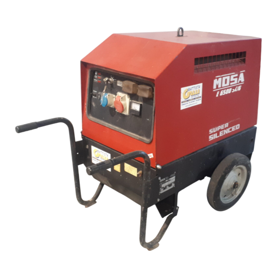
- Page 3 DESCRIZIONE DELLA MACCHINA GE 6000 SX/GS GE 6500 SX/GS REV.4-11/11 I GE 6000 - 6500 sono dei gruppi elettrogeni che trasformano l’energia meccanica, generata da un motore endotermico, in en- ergia elettrica attraverso un alternatore. Sono destinati ad uso industriale e professionale, si compongono di diverse parti principali quali: il motore, l’alternatore, i controlli elettrici ed elettronici ed una struttura protettiva.
- Page 4 Certificati qualità REV.4-03/12 UNI EN ISO 9001 : 2008 L'Azienda ha ottenuto nel 1994 la prima certificazione I vantaggi per i nostri Clienti sono: del proprio Sistema Qualità in accordo alla norma · costanza della qualità dei prodotti e dei servizi, UNI EN ISO 9002;...
- Page 5 Indice GE 6000-6500 SX/GS REV.3-11/11 M 01 CERTIFICATI DI QUALITA’ M 1.01 COPYRIGHT M 1.1 NOTE M 1.4 MARCHIO CE M 1.4.1 DICHIARAZIONE DI CONFORMITA’ M 1.5 DATI TECNICI AVVERTENZE M 2.1 SIMBOLI M 2.5... INSTALLAZIONE ED AVVERTENZE PRIMA DELL’USO M 2.6 AVVERTENZE PER L’INSTALLAZIONE M 2.7...
- Page 6 In ogni caso la MOSA divisione della B.C.S. S.p.A. non sarà ritenuta responsabile per ogni eventuale danno conseguente, diretto o indiretto, in relazione all’uso delle informazioni rese.
- Page 7 Note REV.0-05/00 Introduzione Informazioni di carattere generale All’interno della busta data in dotazione con la macchina e/o apparecchiatura troverete: il libretto Uso Manutenzione Gentile Cliente, e Ricambi, il libretto d’Uso del Motore e gli attrezzi (se desideriamo ringraziarla della Sua attenzione per aver previsti dalla sua dotazione), la garanzia (nei paesi ove è...
- Page 8 MARCHIO CE REV.5-03/11 Su ciascun esemplare di macchina è apposta la marcatura CE che attesta la conformità alle direttive applicabili ed il soddisfacimento dei requisiti essenziali di sicurezza del prodotto; l’elenco di tali direttive è riportato nella dichiarazione di conformità che accompagna ciascun esemplare di macchina.
-
Page 9: Dichiarazione Di Conformita
BCS S.p.A. declara bajo su responsabilidad que la máquina: GRUPPO ELETTROGENO DI SALDATURA / WELDING GENERATOR GRUPPO ELETTROGENO / POWER GENERATOR Marchio / Brand : MOSA Modello / Model : Matricola / Serial number: è conforme con quanto previsto dalle Direttive Comunitarie e relative modifiche: est en conformité... -
Page 10: Dati Tecnici
GE 6000 SX/GS Dati tecnici GE 6500 SX/GS REV.5-12/12 Dati tecnici GE 6000 SX/GS GE 6000 SX/GS-AVR GE 6500 SX/GS GENERATORE *Potenza trifase Stand-by 6.5 kVA (5.2 kW) / 400 V / 9.4 A **Potenza trifase PRP 5.7 kVA (4.6 kW) / 400 V / 8.2 A *Potenza monofase Stand-by 5.7 kVA (5.1 kW) / 230 V / 24.8 A... - Page 11 SIMBOLOGIA E LIVELLI DI ATTENZIONE REV.0-06/00 SIMBOLI ALL’INTERNO DEL MANUALE LIVELLI DI ATTENZIONE - I simboli contenuti all’interno del manuale, hanno lo PERICOLOSO scopo di attirare l’attenzione dell’Utilizzatore al fine di evitare inconvenienti o pericoli sia alle persone che A questo avviso corrisponde un pericolo immediato sia alle cose od al mezzo in possesso.
- Page 12 SIMBOLOGIA E LIVELLI DI ATTENZIONE REV.1-06/10 SIMBOLI DIVIETI Incolumità per le persone STOP - Leggere assolutamente e porre la Uso solo con abbigliamento di sicurezza - dovuta attenzione. E’ fatto obbligo utilizzare i mezzi di protezione personali dati in dotazione. Leggere e porre la dovuta attenzione.
- Page 13 AVVERTENZE (Prima dell'uso) REV.0-06/00 L’installazione e le avvertenze generali delle operazioni, sono finalizzate al corretto utilizzo della macchina e/o apparecchiatura, nel luogo ove è effettuato l’uso come gruppo elettrogeno e/o motosaldatrice. Tenere il motore spento durante il rifornimento. Non maneggiare apparecchia- ture elettriche a piedi nudi o con Non fumare, evitare fiamme, scintille o utensili elettrici in funzione durante le operazioni di rifornimento.
- Page 14 AVVERTENZE PER L'INSTALLAZIONE REV.1-06/07 AVVERTENZE PER L’INSTALLAZIONE PRIMA Verificare che vi sia il ricambio completo dell’aria e che DELL’USO l’aria calda espulsa non ricircoli all’interno del gruppo in modo da provocare un innalzamento pericoloso della MOTORI A BENZINA temperatura. Utilizzare in luogo aperto, ben ventilato o mandare lo ...
- Page 15 Installazione Luftzirkulation GE 6000-6500 SX/GS Installation Instalación GE 7000 SX/GA-EAS Installation REV.1-09/06...
-
Page 16: Dimensions
Dimensioni Abmessungen GE 6000/6500 SX/GS Dimensions Dimensiones GE 7000 SX/GA 2.7.1 Dimensions REV.0-10/01 1040 Ø 14 n°2 fori Ø n°2 fori 1410... - Page 17 IMBALLAGGIO REV.1-02/04 NOTA BENE Assicurarsi che i dispositivi preposti al sollevamento siano: correttamente fissati, adeguati al carico della macchina imballata e conformi alla normativa vigente specifica. Al ricevimento della merce accertarsi che il prodotto non abbia subito danni durante il trasporto: che non ci sia stata manomissione o asportazioni di parti contenute all’interno dell’imballo o della macchina.
- Page 18 TRASPORTO E SPOSTAMENTO GRUPPI BARELLATI REV.2-09/11 ATTENZIONE Il trasporto deve sempre avvenire a motore spento, con cavi elettrici scollegati, batteria d’avviamento scollegata, serbatoio del carburante vuoto. Assicurarsi che i dispositivi preposti al sollevamento siano: correttamente fissati, adeguati al carico della macchina e conformi alla normativa vigente specifica.
- Page 19 CTM2 MONTAGGIO REV.0-06/00 ATTENZIONE L’accessorio CTM non può essere rimosso dalla macchina e utilizzato separatamente (con azionamento manuale) per il trasporto di carichi o comunque per usi diversi dalla movimentazione della macchina. Nota: Sollevare la macchina e montare i particolari indicati in figura...
- Page 20 LUBRIFICANTE all’aperto o in ambienti ben ventilati. OLIO RACCOMANDATO Evitare di rovesciare il combustibile. La MOSA consiglia AGIP per la scelta del tipo d’olio. Pulire eventuali dispersioni prima di Attenersi all’etichetta posta sul motore per i prodotti avviare il motore.
-
Page 21: Arresto Motore
GE 6000/6500 SX/GS AVVIAMENTO E ARRESTO GE 6000/6500 DES/GS-L GE 7000 SX/GA REV.1-09/06 ARRESTO MOTORE controllare giornalmente + Prima delle operazioni d’arresto del motore sono obbligatorie le seguenti operazioni: - l’interruzione del prelievo della potenza sia trifase sia monofase, dalle prese di corrente ausiliarie. NOTA BENE Non alterare le condizioni primarie di regolazione e non manomettere le parti sigillate. - Page 22 LEGENDA STRUMENTI E COMANDI REV.6-07/08 4A Indicatore livello olio idraulico 87 Rubinetto carburante U7 Unità controllo motore EP6 Presa di saldatura ( + ) 88 Siringa olio Voltmetro tensione saldatura 10 Presa di saldatura ( - ) A3 Sorvegliatore d’isolamento V4 Comando invertitore polarità 12 Presa di messa a terra A4 Spia segnalazione pulsante 30 l/1' PTO HI V5 Indicatore pressione olio 15 Presa di corrente in c.a. B2 Unità controllo motore EP2 W1 Interruttore comando a distanza 16 Comando acceleratore / pulsante marcia B3 Connettore E.A.S. W3 Pulsante selezione 30 l/1' PTO HI 17 Pompa di alimentazione B4 Spia segnalazione esclusione PTO HI W5 Voltmetro batteria 19 Presa di corrente 48V (c.c.)
- Page 23 Comandi Bedienelemente GE 6000 SX/GS Controls Mandos GE 6500 SX/GS Commandes REV.1-09/06 GE 6000 (230V Vers.) GE 6000 (230V 110V Vers.) GE 6500 (400V 230V Schuko Vers.) GE 6500 (400V 230V Vers.)
- Page 24 UTILIZZAZIONE COME MOTOGENERATORE CT 230 SX GE 6000 - 6500 SX/GS GE 7000 SX/GA REV.0-06/05 ☞ MACCHINA CON PROTEZIONE TERMICA E’ assolutamente vietato collegare il gruppo alla rete pubblica e/o comunque con un’al- Nel momento in cui si supera la potenza massima tra fonte di energia elettrica.
- Page 25 UTILIZZAZIONE DEGLI ACCESSORI COMANDO A DISTANZA 38.5 TCM 15 - 6 REV.2-07/11 ASSICURARSI Quando vengono utilizzati i TCM 15-6 non è possibile collegare il quadro di intervento automatico E.A.S. USO DEL COMANDO TCM 15 TCM 15 L’abbinamento del TCM 15 con il gruppo elettrogeno, predisposto per l’avviamento a distanza, permette di intervenire sul gruppo stesso da lontano.
- Page 26 PROTEZIONE MOTORE ES - EV 39.4 REV.1-02/03 MOTORE CON PROTEZIONE (ES - EV) I dispositivi ES o EV assicurano la protezione del motore in caso di bassa pressione olio ed alta temperatura. Il sistema è costituito da una scheda elettronica di Alta temperatura comando e controllo e da un dispositivo di arresto motore: solenoide (ElettroStop.), elettrovalvola...
- Page 27 Ricerca Guasti 40.2 Motore diesel REV.3-06/06 Problema Possibile causa Rimedio MOTORE Il motore non si avvia 1) Selettore d'avviamento (I6) (ove montato) 1) Verificare posizione in posizione errata 2) Pulsante d'emergenza (L5) premuto 2) Sbloccare 3) Preriscaldo (ove montato) 3) Mancata o insufficiente fase di preriscaldo candelette.
- Page 28 Ricerca Guasti 40.2.1 Motore diesel REV.4-03/11 Problema Possibile causa Rimedio GENERAZIONE Assenza di tensione in uscita. 1) Commutatore di tensione in posizione 0. 1) Verificare posizione 2) Commutatore di tensione difettoso. 2) Controllare collegamenti e funzionamento del commutatore. Riparare o sostituire. 3) Intervento protezione per sovraccarico.
-
Page 29: Avvertenze
MANUTENZIONE REV.1-06/10 ATTENZIONE Avvalersi di personale qualificato per effettuare la manutenzione ed il lavoro di ricerca dei guasti. E’ obbligatorio fermare il motore prima di effettuare qualunque manu- tenzione alla macchina. A macchina in funzione prestare attenzione a: - Parti rotanti - Parti calde (collettori e silenziatori di scarico, turbine, e/o altro) - Parti in tensione. - Page 30 MANUTENZIONE 43.1 REV.0-09/05 ATTENZIONE Tutte le operazioni di manutenzione sul gruppo elettrogeno predisposto per l'intervento automatico devono essere effettuate con il quadro in modalità RESET. Le operazioni di manutenzione sui quadri elettrici dell'impianto devono essere effettuate in completa sicurezza sezionando tutte le fonti di alimentazione esterna: RETE, GRUPPO e BATTERIA.
- Page 31 RIMESSAGGIO REV.0-06/00 Nel caso in cui la macchina non fosse utilizzata per un periodo superiore ai 30 giorni, accertarsi che l’ambiente in cui è rimessa assicuri un adeguato riparo da fonti di calore, mutamenti meteorologici od ogni quant’altro possa provocare ruggine, corrosione o danni in genere al prodotto stesso.
- Page 32 DISMISSIONE REV.0-06/00 Avvalersi di personale qualificato per effettuare le operazioni necessarie alla dismissione. Per dismissione s’intendono tutte le operazioni da effet- tuare, a carico dell’utilizzatore, quando l’impiego della macchina ha avuto termine. In caso di necessità per le avvertenze di primo soc- Questo comprende le operazioni di smontaggio della macchina, la suddivisione dei vari elementi per un corso e le misure antincendio, vedere pag.
- Page 33 GE 6000 SX/GS GE 6000 SX/GS-AVR GE 6500 SX/GS 1 2 1 2 356409003 - GB ENGLISH © MOSA 21/10/04 35640M00 preparato da UPT approvato da DITE...
- Page 35 DESCRIPTION OF THE MACHINE GE 6000 SX/GS GE 6500 SX/GS REV.4-11/11 The generating set GE 6000 / 6500 is a unit which transforms the mechanical energy, generated by endothermic engine, into electric energy, through an alternator. Is meant for industrial and professional use, powered by an endothermic engine; it is composed of various main parts such as: engine, alternator, electric and electronic controls, the fairing or a protective structure.
- Page 36 · Competent support in the solution of problems; ofthe International Certification Network IQNet, · Information and training in the correct applicatio- awarded the official approval to MOSA after an- nand use of the products to assure the security examination of its operations at the head office ofthe operator and protect the environment;...
-
Page 37: Spare Parts
Index GE 6000-6500 SX/GS REV.3-11/11 M 01 QUALITY SYSTEM M 1.01 COPYRIGHT M 1.1 NOTES M 1.4 CE MARK M 1.4.1 DECLARATION OF CONFORMITY M 1.5 TECHNICAL DATA SYMBOLS AND SAFETY PRECAUTIONS M 2.1 SYMBOLS M 2.5 -…. INSTALLATION AND ADVICE BEFORE USE M 2.6 INSTALLATION AND ADVICE M 2.7... - Page 38 (see page M1.1). All rights are reserved to said Company. It is a property logo of MOSA division of B.C.S. S.p.A. All other possible logos contained in the documen- tation are registered by the respective owners.
- Page 39 Notes REV.0-10/02 INFORMATION INFORMATION OF GENERAL TYPE In the envelope given together with the machine and/or Dear Customer, set you will find: the manual for Use Maintenance and We wish to thank you for having bought a high quality set. Spare Parts, the manual for use of the engine and the tools (if included in the equipment), the guarantee (in the Our sections for Technical Service and Spare Parts will...
- Page 40 CE MARK REV.5-03/11 Any of our product is labelled with CE marking attesting its conformity to appliable directives and also the fulfillment of safety requirements of the product itself; the list of these directives is part of the declaration of conformity included in any machine standard equipment. Here below the adopted symbol: CE marking is clearly readable and unerasable and it can be either part of the data-plate.
-
Page 41: Dichiarazione Di Conformita
BCS S.p.A. declara bajo su responsabilidad que la máquina: GRUPPO ELETTROGENO DI SALDATURA / WELDING GENERATOR GRUPPO ELETTROGENO / POWER GENERATOR Marchio / Brand : MOSA Modello / Model : Matricola / Serial number: è conforme con quanto previsto dalle Direttive Comunitarie e relative modifiche: est en conformité... - Page 42 GE 6000 SX/GS Technical data GE 6500 SX/GS REV5-12/12 Technical data GE 6000 SX/GS GE 6000 SX/GS-AVR GE 6500 SX/GS A.C. GENERATOR *Three-phase power Stand-by 6.5 kVA (5.2 kW) / 400 V / 9.4 A **Three-phase power PRP 5.7 kVA (4.6 kW) / 400 V / 8.2 A *Single-phase power Stand-by 5.7 kVA (5.1 kW) / 230 V / 24.8 A...
-
Page 43: Symbols In This Manual
SYMBOLS AND SAFETY PRECAUTIONS REV.0-11/99 SYMBOLS IN THIS MANUAL SAFETY PRECAUTIONS DANGEROUS The symbols used in this manual are designed to call your attention to important aspects of the operation of the machine as well as potential hazards and dangers This heading warns of an immediate danger for persons for persons and things. - Page 44 SYMBOLS AND SAFETY PRECAUTIONS REV.2-06/10 SYMBOLS PROHIBITIONS No harm for persons Use only with safety clothing - STOP - Read absolutely and be duly attentive It is compulsory to use the personal protection means given in equip- ment. Use only with safety clothing - Read and pay due attention It is compulsory to use the personal protection means given in equipment.
- Page 45 INSTALLATION AND ADVICE BEFORE USE REV.0-06/00 The installation and the general advice concerning the operations, are finalized to the correct use of the ma- chine, in the place where it is used as generator group and/or welder. Stop engine when fueling Do not touch electric devices if you are barefoot or with wet Do not smoke, avoid flames, sparks or electric tools when fueling.
- Page 46 INSTALLATION AND ADVICE REV.1-06/07 Check that the air gets changed completely and the hot INSTALLATION AND ADVICE BEFORE USE air sent out does not come back inside the set so as to cause a dangerous increase of the temperature. GASOLINE ENGINES Use in open space, air swept or vent exhaust gases, which contain the deathly carbone oxyde, far from the work area.
- Page 47 Installazione Luftzirkulation GE 6000-6500 SX/GS Installation Instalación GE 7000 SX/GA-EAS Installation REV.1-09/06...
-
Page 48: Dimensions
Dimensioni Abmessungen GE 6000/6500 SX/GS Dimensions Dimensiones GE 7000 SX/GA 2.7.1 Dimensions REV.0-10/01 1040 Ø 14 n°2 fori Ø n°2 fori 1410... - Page 49 UNPACKING REV.1-02/04 NOTE + Be sure that the lifting devices are: correctly mounted, adequate for the weight of the machine with it’s pack- aging, and conforms to local rules and regulations. When receiving the goods make sure that the product has not suffered damage during the transport, that there has not been rough handling or taking away of parts contained inside the packing or in the set.
- Page 50 TRANSPORT AND DISPLACEMENTS COVERED UNITS REV.2-09/11 NOTE Transportation must always take place with the engine off, electrical cables and starting battery disconnected and fuel tank empty. Be sure that the lifting devices are: correctly mounted, adequate for the weight of the machine with it’s packaging, and conform to local rules and regulations.
- Page 51 CTM2 ASSEMBLY REV.0-06/00 ATTENTION The CTM accessory cannot be removed from the machine and used separately (actioned manually or following vehicles) for the transport of loads or anyway for used different from the machine movements. Note: Lift the machine and assemble the parts as shown in the drawing...
-
Page 52: Grounding Connection
LUBRICANT motor. RECOMMENDED OIL MOSA recommends selecting AGIP engine oil. Refill the tank with good quality diesel fuel, such as Refer to the label on the motor for the recommended automobile type diesel fuel, for example. -
Page 53: Stopping The Engine
GE 6000/6500 SX/GS ENGINE STARTING - STOPPING THE ENGINE GE 6000/6500 DES/GS-L GE 7000 SX/GA REV.1-09/06 STOPPING THE ENGINE Check daily Before stopping the engine it is compulsory to effect the following operations: - stop to draw three/single-phase current from the auxiliary sockets. - Page 54 CONTROLS LEGENDE REV.2-07/08 Hydraulic oil level light Exclusion indicating light PTO HI Battery voltmeter Welding socket ( + ) Auxiliary current push button Remote control socket Welding socket ( - ) Fuel level light Button indicating light 20 l/1' PTO HI Earth terminal E.A.S. PCB Commutator/switch, serial/parallel A.C. socket Control unit for generating sets QEA Thermal-magnetic circuit breaker Accelerator lever Selection push button 20 l/1' PTO HI Ground fault interrupter ( 30 mA ) Feed pump Water temperature indicator Engine control unit and economiser 48V D.C. socket Engine air filter Ammeter Oil level dipstick Frequency meter Engine oil reservoir cap Frequency rpm regulator 24A Hydraulic oil reservoir cap Voltmeter regulator 24B Water filling cap Fuse Fuel prefilter Stop switch Fuel tank cap Warning light, high temperature Muffler Arc-Force selector...
- Page 55 Comandi Bedienelemente GE 6000 SX/GS Controls Mandos GE 6500 SX/GS Commandes REV.1-09/06 GE 6000 (230V Vers.) GE 6000 (230V 110V Vers.) GE 6500 (400V 230V Schuko Vers.) GE 6500 (400V 230V Vers.)
- Page 56 CT 230 SX USE AS A GENERATOR GE 6000 - 6500 SX/GS GE 7000 SX/GA REV.0-06/99 ☞ THERMOPROTECTION It is strictly forbidden to connect the group to the public mains a/o to another source of If you overload the genset the thermoprotection will electric power.
- Page 57 ACCESSORY USE REMOTE CONTROL 38.5 TCM 15 - 6 REV.1-07/11 MAKE SURE When the TCM 15 - 6 is used, it is not possible to connect the E.A.S automatic intervention unit. USE OF THE REMOTE CONTROL TCM 15 The coupling of the TCM 15 with the generating set, TCM 15 permits to work far from the set itself.
- Page 58 USE OF THE PROTECTION ENGINE PROTECTION 39.4 ES - EV REV..1-04/03 ENGINE PROTECTION (ES - EV) The devices ES or EV ensure the protection of the engine in case of low oil pressure or engine high temperature. The system consist of electronic card of control High temperature and check, and of an engine stop device: solenoid (ElettroStop), electrovalve (ElettroValvola)
- Page 59 Diesel engine 40.2 Troubleshooting REV.3-07/06 Problem Possible cause Solution ENGINE The motor does not start up 1) Start-up switch (I6) (where it is assembled) in 1) Check position incorrect position 2) Emergency button (L5) pressed 2) Unblock 3) Preheating (where it is assembled) 3) Lacking or insufficient preheating phase for sparkplugs.
- Page 60 Troubleshooting Diesel engine 40.2. REV.4-03/11 Problem Possible cause Solution GENERATOR Absence of output voltage Voltage switch in position 0 Check position Voltage switch faulty Check connections and working of the switch, repair or replace Protection tripped due to overload Check the load connected and diminish Differential protection device tripped.
-
Page 61: Important
MAINTENANCE REV.0-06/10 WARNING ● Have qualified personnel do maintenance and troubleshooting work. ● Stop the engine before doing any work inside the machine. If for any reason the machine must be operated while working inside, pay at- tention moving parts, hot parts (exhaust manifold and muffler, etc.) electrical parts which may be unprotected when the machine is open. - Page 62 43.1 MAINTENANCE REV.0-09/05 ATTENTION Maintenance operations on the electricity-generating group prearranged for automatic operation must be carried out with the panel in RESET mode. Maintenance operations on the installation’s electrical panels must be carried out in complete safety by cutting off all external power sources: ELECTRICAL POWER, GROUP and BATTERY.
-
Page 63: Gasoline Engine
STORAGE REV.0-06/07 In case the machine should not be used for more than 30 days, make sure that the room in which it is stored presents a suitable shelter from heat sources, weather changes or anything which can cause rust, corrosion or damages to the machine. - Page 64 CUST OFF REV.0-06/07 Have qualified personnel disassemble the In case of necessity for first aid and fire prevention, machine and dispose of the parts, including the see page M2.5. oil, fuel, etc., in a correct manner when it is to be taken out of service.
- Page 65 GE 6000 SX/GS GE 6000 SX/GS-AVR GE 6500 SX/GS 1 2 1 2 356409003 - F FRANCAIS © MOSA 21/10/04 35640M00 preparato da UPT approvato da DITE...
- Page 67 GE 6000 SX/GS DESCRIPTION DE LA MACHINE GE 6500 SX/GS REV.4-11/11 Le GE 6000 / 6500 et un groupe électrogène qui transforme l’énergie mécanique, générée par un moteur endothermique, en énergie électrique à travers un alternateur. Il est destiné à l’usage industriel et professionnel, actioné par un moteur endothermique, il se compose de differéntes parties principales comme: le moteur, l’alternateur, les contrôles électriques et électroniques, la carrosserie ou une structure de protection.
- Page 68 CERTIFICATS DE QUALITE REV.4-03/12 UNI EN ISO 9001 : 2008 MOSA a obtenu en 1994 la primière certification · constance de la qualité des produits et desservices, deson système Qualité en accord avec la norme toujours à la hauteur des attentes duclient;...
-
Page 69: Pieces De Rechanges
GE 6000-6500 SX/GS Index REV.3-11/11 M 01 CERTIFICATS DE QUALITE M 1.01 COPYRIGHT M 1.1 NOTES M 1.4 CE MARQUE M 1.4.1 DECLARATION DE CONFORMITE M 1.5 DONNEES TECHNIQUES M 2 - ... SYMBOLES ET NIVEAUX D’ATTENTION M 2.1 SYMBOLES ET NIVEAUX D’ATTENTION M 2.5 -…. - Page 70 à la création et auprojet pour la communication, comme prévu par les lois en vigueur à ce sujet. En tout cas MOSA division de B.C.S. S.p.A. ne sera pas jugée responsable pour tout dommage éven- tuel conséquent, direct ou indirect, en relation avec l’usage des informations données.
-
Page 71: Informations De Caractere General
Note REV.1-11/01 INTRODUCTION INFORMATIONS DE CARACTERE GENERAL Cher Client, A l’intérieur de la pochette donnée en équipement avec Nous désirons vous remercier de votre attention pour la machine et/ou l’appareil vous trouverez: le manuel avoir acheté un groupe de haute qualité. Emploi Entretien et Rechanges, le manuel du Moteur et les outils (si prévus par l’équipement), la garantie (dans Nos Services d’assistance technique et de Rechanges... - Page 72 CE MARQUE REV.5-03/11 Chacun de nos produits est equippé avec une marque CE qui affirme la conformité aux directivesen vigueur et qui affirme aussi la conformité du produit aux mesures de securité valables pendant son utilisation; la liste de ces directives est aussi jointe à la declaration de conformitè livrèe avec chaque machine. Le symbole utilisé...
-
Page 73: Dichiarazione Di Conformita
BCS S.p.A. declara bajo su responsabilidad que la máquina: GRUPPO ELETTROGENO DI SALDATURA / WELDING GENERATOR GRUPPO ELETTROGENO / POWER GENERATOR Marchio / Brand : MOSA Modello / Model : Matricola / Serial number: è conforme con quanto previsto dalle Direttive Comunitarie e relative modifiche: est en conformité... -
Page 74: Niveau Puissance Acoustique
GE 6000 SX/GS Donnes techniques GE 6500 SX/GS REV.5-12/12 Données techniques GE 6000 SX/GS GE 6000 SX/GS-AVR GE 6500 SX/GS GENERATEUR EN C.A. *Puissance triphasée Stand-by 6.5 kVA (5.2 kW) / 400 V / 9.4 A **Puissance triphasée PRP 5.7 kVA (4.6 kW) / 400 V / 8.2 A *Puissance monophasée Stand-by... -
Page 75: Dangereux
GE_, MS_, TS_ SYMBOLES ET NIVEAUX D’ATTENTION 1.0-02/98 SYMBOLES A L’INTERIEUR DU MANUEL NIVEAUX D’ATTENTION DANGEREUX - Les symboles contenus dans le manuel ont pour but d’attirer l’attention de l’usager afin d’éviter des incon- A cet avis correspond un danger immédiat tant pour vénients ou dangers tant aux personnes qu’aux choses les personnes que pour les choses: pour les premières ou à... -
Page 76: Symboles Et Niveaux D'attention
SYMBOLES ET NIVEAUX D’ATTENTION REV.2-06/10 INTERDICTIONS SYMBOLES Sécurité pour les personnes STOP - A lire absolument et apporter l’attention Emploi seulement avec vêtements de sécurité - voulue. On est obligé d’utiliser les moyens de protectionpersonnels donnés en équipement. Lire et accorder l’attention voulue. Utilisation seulement avec habillement de sécurité... -
Page 77: Moyens D'extinction
AVIS (AVANT USAGE) REV.1-05/03 L’installation et les instructions générales des opérations visent à l’utilisation correcte de la machine dans lelieu où elle est employée comme groupe électrogène et/ou motosoudeuse. Eteindre le moteur pendant le ravitaillement. Ne pas manipuler d'appareils électriques pieds nus ou avec Ne pas fumer, éviter flammes, étincelles ou outils électriques pendant les opérationsde ravitaillement. - Page 78 AVIS POUR L'INSTALLATION REV.2-06/07 INSTALLATION ET AVIS AVANT L’USAGE Vérifier qu’il y ait le changement complet de l’air et que l’air chaud expulsé ne recircule pas à l’intérieur du groupe MOTEURS A ESSENCE de façon à provoquer une élévation dangereuse de la Utiliser en lieu ouvert, bien ventilé...
- Page 79 Installazione Luftzirkulation GE 6000-6500 SX/GS Installation Instalación GE 7000 SX/GA-EAS Installation REV.1-09/06...
-
Page 80: Dimensions
Dimensioni Abmessungen GE 6000/6500 SX/GS Dimensions Dimensiones GE 7000 SX/GA 2.7.1 Dimensions REV.0-10/01 1040 Ø 14 n°2 fori Ø n°2 fori 1410... -
Page 81: Emballage
EMBALLAGE REV.1-02/04 NOTE + A la réception de la marchandise s’assurer que le produit n’a pas subi de dommages pendant le transport; qu’il n’y a pas eu de manipulation ou d’enlèvement de pièces contenues dans l’emballage ou de l’appareil. Si l’on trouvait des dommages, manipulations ou enlèvements de pièces (enveloppes, livrets, etc.), nous vous recommandons de le communiquer im- médiatement à... -
Page 82: Transport Et Deplacement Groupe Carrosses
TRANSPORT ET DEPLACEMENT GROUPE CARROSSES REV.2-09/11 ATTENTION Le transport doit s’effectuer avec moteur arrêté, branchements électriques déclenchés, batterie débranchée, réservoir vide. S’assurer que les dispositif préposés au lavage soient: correctement fixés, adaptés au chargement de la machine et conformes aux specifiques normatives en vigueur. S’assurer aussi que l’endroit de travail soit attendu que par personnel autorisé... -
Page 83: Montage
CTM2 MONTAGE REV.0-06/00 ATTENTION L’accessoire CTM ne peut être retiré de la machine et utilisé séparément (avec actionnement manuel ou à la suite devéhicules) pour le transport de charges ou de toute façon puor usages différents de celui des mouvements de la machine. Note: Soulever la machine et monter les pièces indiquées dans la figure... -
Page 84: Batterie Sans Entretien
à l'air libre ou dans des HUILE RECOMMANDE locaux bien ventilés. Eviter de renverser MOSA conseille AGIP pour la choix de type d’huile. le combustible. Nettoyer d'éventuelles S’en tenir à l’étiquette mise sur le moteur pour les dispersions avant de faire partir le produits recommandée. -
Page 85: Fdemarrage Et Arret
GE 6000/6500 SX/GS GE 6000/6500 DES/GS-L DEMARRAGE ET ARRET GE 7000 SX/GA REV.1-09/06 ARRET DU MOTEUR contrôler journellement Avant les opérations d’arrêt du moteur, les ope- rations suivantes sont obligatoires: - l’interruption du prélèvement de puissance, tant triphasée que monophasée, des prises de courant auxiliaire NOTA BENE Ne pas changer les conditions primaires de ré-... -
Page 86: Legende Strumentes Et Commandes
LEGENDE STRUMENTES ET COMMANDES REV.2-10/07 4A Indicateur niveau huile hydraulique A3 Contrôle d’isolation W3 Bouton sélection 30 I/1' PTO HI Prise de soudage ( + ) A4 Voyant indication bouton 30 I/1' PTO HI W5 Voltmètre batterie 10 Prise de soudage ( - ) B2 Protection moteur EP2 X1 Prise pour télécommande 12 Prise de mise à terre B3 Connecteur E.A.S. Y3 Voyant indication bouton 20 I/1' PTO HI 15 Prises de courant en c.a. B4 Voyant indication exclusion PTO HI Y5 Commutateur Série/Parallèle 16 Commande accélérateur / bouton marche B5 Bouton courant auxiliaire Z2 lnterrupteur magnétothermique 17 Pompe alimentation C2 Indicateur niveau carburant Z3 Bouton sélection 20 I/1' PTO HI... - Page 87 Comandi Bedienelemente GE 6000 SX/GS Controls Mandos GE 6500 SX/GS Commandes REV.1-09/06 GE 6000 (230V Vers.) GE 6000 (230V 110V Vers.) GE 6500 (400V 230V Schuko Vers.) GE 6500 (400V 230V Vers.)
- Page 88 CT 230 SX USE AS A GENERATOR GE 6000 - 6500 SX/GS GE 7000 SX/GA REV.0-06/99 ☞ THERMOPROTECTION It is strictly forbidden to connect the group to the public mains a/o to another source of If you overload the genset the thermoprotection will electric power.
-
Page 89: Utilisation Des Accessoires
REMOTE CONTROL 38.5 UTILISATION DES ACCESSOIRES TCM 15 - 6 REV.1-07/11 ATTENTION Quand on utilise le TCM 15 - 6 il n’est pas possible de brancher le cadre d’intervention automatique EAS UTILISATION DE LA TCM 15 TCM 15 L’accouplement du TCM 15 avec le groupe élec- trogène prédisposé... -
Page 90: Moteur Avec Protection Es - Ev
39.4 PROTECTION MOTEUR ES - EV REV.1-02/03 MOTEUR AVEC PROTECTION ES - EV Les dispositifs ES ou EV assuront la protection du moteur en cas de basse pression de l’huile et haute température du moteur. Le systèm est costitué d'une fiche électronique de Haute température commande et contrôle et d'un dispositif d'arrêt du moteur: solénoïd (ElettroStop), électrosoupape... -
Page 91: Recherche Des Pannes
40.2 Recherche des pannes Moteur diesel REV.3-07/06 Problème Cause possible Remède MOTEUR Le moteur ne part pas 1) Sélecteur de démarrage (I6) (où il est monté) 1) Vérifier position en position erronée 2) Bouton d'urgence (L5) pressé 2) Débloquer 3) Préchauffage (où il est monté) 3) Phase de préchauffage des bougies manquée ou insuffisante Avarie dans le circuit, réparer. - Page 92 40.2.1 Recherche des pannes Moteur diesel REV.4-03/11 Problème Cause possible Remède GENERATOR 1) Commutateur de tension en position 0 1) Vérifier position Absence de tension en 2) Commutateur de tension défectueux 2) Contrôler branchements et fonctionnement du sortie commutateur. Réparer ou remplacer. 3) Intervention protection pour surcharge.
-
Page 93: Important
ENTRETIEN REV.1-06/10 ATTENTION • Avoir du personnel qualifié pour effectuer l’entretien et le travail de recherche des pannes. • Arrèter le moteur avant d’effectuer tout entretien de la machine. Quand la machine est en marche, faire ATTENTION aux parties en mouvement et chaudes (collecteurs et pots d’échappement, turbines et/ ou autres)- Pièces sous tension. - Page 94 43.1 ENTRETIEN REV.0-09/05 ATTENTION • Toutes les opérations d'entretien sur le groupe électrogène prèvu pour l'intervention automatique doivent être effectuées avec le cadre en modalité RESET. • Les opérations d'entretien sur les cadres électriques de l'installation doivent être effectuées en complète sécurité, en sec- tionnant toutes les sources d'alimentation extérieure: RESEAU, GROUPE ET BATTERIE.
-
Page 95: Moteurs A Essence
REMISAGE REV.0-09/97 Au cas où l’on n’utiliserait pas la machine pendant plus de 30 jours, s’assurer que le milieu où elle est remisée garantisse un abri des sources de chaleur, changements météorologiques ou tout ce qui peut provoquer rouille, corrosion ou dommages en général. +Avoir du personnel qualifié... - Page 96 MISE HORS D’USAGE REV.0-09/97 En cas de besoin pour les instructions de premier secours + Avoir du personnel qualifié pour effectuerles opé- rations nécessaires de mise hors d’usage Par mise et les mesures anti-incendie, voir page M2.5. hors d’usage on entend toutes les opérations à effectuer, à...
- Page 97 GE 6000 SX/GS GE 6000 SX/GS-AVR GE 6500 SX/GS 1 2 1 2 356409003 - E ESPAÑOL © MOSA 21/10/04 35640M00 preparato da UPT approvato da DITE...
- Page 99 GE 6000 SX/GS DESCRIPCIÓN DE LA MÁQUINA GE 6500 SX/GS REV.4-11/11 El GE 6000 - 6500 es un grupo electrógeno que transforma la energía mecánica, generada por un motor endotérmico, en energía eléctrica mediante un alternador. Está destinado al uso industrial y profesional, se compone de distintas partes principales como: el motor, el alternador, los con- troles eléctricos y electrónicos y una estructura protectora.
- Page 100 IQNet, ha otorgado el prestigioso reconocimiento aplicables para el uso de los productos, para la a MOSA por su actividad desarrollada en la sede y seguridad de los operadores y el respeto del medio la planta de producción de Cusago (MI).
- Page 101 GE 6000-6500 SX/GS ÍNDICE REV.3-11/11 M 01 CERTIFICADOS DE CALIDAD M 1.01 COPYRIGHT M 1.1 NOTAS M 1.4 MARCA CE M 1.4.1 DECLARACIÓN DE CONFORMIDAD M 1.5 DATOS TÉCNICOS M 2 ..SÍMBOLOS Y NIVELES DE ATENCIÓN M 2.1 SÍMBOLOS Y NIVELES DE ATENCIÓN M 2.5 -….
- Page 102 Aconsejamos de dar la debida atención a las pági- nas relativas a la seguridad. Todos los derechos estan reservados a esta. Es una marca de propiedad de MOSA división de B.C.S. S.p.A. Todas las otras marcas eventuales contenidad en la documentación estan registradas por los amos respectivos.
- Page 103 Notas REV.0-11/00 INTRODUCCIÓN INFORMACIÓN DE CARÁCTER GENERAL Apreciado Cliente, deseamos expresar nuestra gratitud En el interior de la bolsa que se entrega con la máquina por su atención al comprar un grupo de alta calidad. y/o las herramientas hay: el libro de Uso Mantenimiento Nuestros departamentos del Servicio de Asistencia y Recambios, el libro de Uso del Motor y las herramientas Técnica y de Recambios trabajarán de la mejor manera...
- Page 104 Marca CE REV.4-03/11 En cada ejemplar de máquina está incluida la marca CE que certifica la conformidad con las directivas aplicables y el cumplimiento de los requisitos esenciales de seguridad del producto; la relación de tales directivas está incluida en la declaración de conformidad que acompaña cada una de las máquinas. El símbolo utilizado es el siguiente: La marca CE está...
-
Page 105: Dichiarazione Di Conformita
BCS S.p.A. declara bajo su responsabilidad que la máquina: GRUPPO ELETTROGENO DI SALDATURA / WELDING GENERATOR GRUPPO ELETTROGENO / POWER GENERATOR Marchio / Brand : MOSA Modello / Model : Matricola / Serial number: è conforme con quanto previsto dalle Direttive Comunitarie e relative modifiche: est en conformité... - Page 106 GE 6000 SX/GS Datos técnicos GE 6500 SX/GS REV.5-12/12 Datos técnicos GE 6000 SX/GS GE 6000 SX/GS-AVR GE 6500 SX/GS GENERADOR *Potencia trifásica Stand-by 6.5 kVA (5.2 kW) / 400 V / 9.4 A **Potencia trifásica PRP 5.7 kVA (4.6 kW) / 400 V / 8.2 A *Potencia monofásica Stand-by...
-
Page 107: Consejos Importantes
SÍMBOLOS Y NIVELES DE ATENCIÓN REV.0-07/98 SÍMBOLOS EN EL INTERIOR DEL MANUAL NIVELES DE ATENCIÓN - Los símbolos contenidos en el manual tienen la finali- PELIGROSO dad de atraer la atención del usuario para evitar incon- venientes o peligros para las personas las cosas o el Este aviso se refiere a un peligro inmediato tanto paraper- instrumento en cuestión. - Page 108 SÍMBOLOS Y NIVELES DE ATENCIÓN REV.1-06/10 PROHIBICIONES SÍMBOLOS Integridad de personas y cosas Uso sólo con indumentaria de seguridad - STOP - Leer imperativamente y prestar la Es obligatorio usar los medios de atención debida. proteccion personal entregados con la máquina. Leer y prestar la debida atención.
- Page 109 ADVERTENCIAS ANTES DEL USO REV.0-01/01 La instalación y las advertencias generales de las operaciones, son finalizadas al corecto utilizo de la máquina,en el lugar donde se trabaja con la máquina sea como grupo electrogeno o sea como motosaldadora. Tener el motor parado durante el llenado No manejar aparejos eléctricos conlos pies desnudos o sea No fumar, evitar llamas, chispas o utensilios eléctricos en función durante las operacionesde llenado...
-
Page 110: Emplazamiento De La Máquina
ADVERTENCIAS POR LA INSTALACIÓN REV.1-06/07 INSTALACIÓN Y ADVERTENCIAS ANTES DEL USO Verificar que haya siempre un ricambio completo de aire, y que el aire caliente de la máquina venga expulsada y MOTORES DE GASOLINA que no vuelva a entrar en el normal circuito de refria- Usar en un lugar abierto bien ventilado o enviar los mento de aire fresco para evitar un aumento peligroso ... - Page 111 Installazione Luftzirkulation GE 6000-6500 SX/GS Installation Instalación GE 7000 SX/GA-EAS Installation REV.1-09/06...
-
Page 112: Dimensions
Dimensioni Abmessungen GE 6000/6500 SX/GS Dimensions Dimensiones GE 7000 SX/GA 2.7.1 Dimensions REV.0-10/01 1040 Ø 14 n°2 fori Ø n°2 fori 1410... - Page 113 EMBALAJE REV.1-02/04 NOTA + Cuando se reciba la mercancía es preciso compro- barque el producto no haya recibido ningún daño durante el transporte: que no haya sido adulterado ni se hayasacado piezas del interior del embalaje o de la máquina. En caso de apreciar daños, adulteraciones o sustrac- ción de elementos (bolsas, libros, etc.) recomenda- mos que se comunique inmediatamente a nuestro Servicio de Asistencia Técnica. Para la eliminación de los materiales utilizados para el embalaje, el usuario deberá atenerse alas normas vigentes en su país. 1) Sacar la máquina (C) del embalaje de expedición. Sacar el manual de uso y mantenimiento (B) del- sobre (A). 2) Leer: el manual de uso y mantenimiento (B), las placas de la máquina y la placa de datos.
- Page 114 TRANSPORTE Y DESPLAZAMIENTOS DE GRUPOS CON CAPÓ REV.2-09/11 ATENCIÓN El transporte se debe efectuar siempre con el motor apagado, con los cables eléctricos desconectados, la batería de arranque desconectada y el depósito de carburante vacío. Asegurarse que los dispositivos de levantamiento están: bien fijados, justos por el cargo de la maquina y tienen que conformarse a las normas especificas que vigen.
- Page 115 CTM2 MONTAJE REV.0-06/00 ATENCIÓN El accesorio CTM no puede ser desmontado de la máquina y utilizado separadamente (sea con uso manual sea como remolquepuesto a un vehiculo) para transporte de cargas o para cualquier uso distinto del propio desplazamiento de la máquina. Nota: Levantar la máquina y montar las piezas indicadas en la figura.
- Page 116 Refrigerados con aire PREAJUSTE Y USO (Motor diesel) REV.1-09/05 BATERÍA SIN MANUTENCIÓN FILTRO A BAÑO DE ACEITE Con el mismo aceite usado para el motor,llenar tam- Conectar el cable + (positivo) bién el filtro de aire hasta el nivelindicado en el filtro. al polo + (positivo) de la bateria (quitando la protección), apre- tando con decisión elborne.
- Page 117 GE 6000/6500 SX/GS GE 6000/6500 DES/GS-L PUESTA EN MARCHA Y PARADA DEL MOTOR GE 7000 SX/GA REV.1-09/06 PARADA contrôler journellement Antes de la parada del motor son obligatorias las siguientes operaciones: - interrompir el uso de la potencia sea trifase o monofase desde las tomas de corriente auxiliares NOTA No alterar las condiciones primarias de regula-...
-
Page 118: Leyenda Esquema Eléctrico
LEYENDA ESQUEMA ELÉCTRICO REV.2-10/07 4A Indicador nivel aceite hidráulico A4 Piloto señalización pulsador 30 l/1' PTO HI Y3 Piloto señalización pulsador 20 l/1' PTO HI Toma de soldadura ( + ) B2 Unidad control motor EP2 Y5 Contactor Serie/Paralelo 10 Toma de soldadura ( - ) B3 Conector E.A.S. Z2 Interruptor magnetotérmico 12 Toma de puesta a tierra B4 Piloto señalización exclusión PTO HI Z3 Pulsador selección 20 l/1' PTO HI 15 Toma de corriente en c.a B5 Pulsador habilitación generación auxiliar Z5 Indicador temperatura agua 16 Mando de aceleración / pulsador marcha C2 Indicador nivel combustible 17 Bomba de alimentación C3 Tarjeta E.A.S. 19 Toma de corriente 48V (c.c.) C6 Unidad logica QEA 22 Filtro aire motor... - Page 119 Comandi Bedienelemente GE 6000 SX/GS Controls Mandos GE 6500 SX/GS Commandes REV.1-09/06 GE 6000 (230V Vers.) GE 6000 (230V 110V Vers.) GE 6500 (400V 230V Schuko Vers.) GE 6500 (400V 230V Vers.)
- Page 120 CT 230 SX GE 6000 - 6500 SX/GS USO COMO MOTOGENERADOR GE 7000 SX/GA REV.0-04/05 ☞ MÁQUINA CON PROTECCIÓN TÉRMICA Es absolutamente prohibido conectar el Cuando se supera la potencia máxima continuativa grupo a la red pública o de cualquier manera o la corriente de carga la protección térmica se con otra fuente de energia electrica.
- Page 121 MANDO A DISTANCIA 38.5 USO DE LOS ACCESORIOS TCM 15 - 6 REV.2-07/11 COMPROBAR Cuando se usan los TCM 15-6 no es posible conectar el cuadro de intervención automática E.A.S USO DEL MANDO TCM 15 TCM 15 La puesta en marcha del TCM15 con el grupo electrógeno predispuesto para el arranque a distancia permite intervenir en el mismo grupo desde lejos.
- Page 122 PROTECCIÓNES MOTOR ES - EV 39.4 REV.1-04/03 MOTOR CON PROTECCIÓN (ES - EV) Los dispositivos ES o EV asegura la protección del motor en caso de baja presión de aceite y alta temperatura. El sistema está constituido por una tarjeta Alta temperatura electrónica de mando y control y por un dispositivo de parada del motor: solenoide (ElectroStop.),...
-
Page 123: Búsqueda Averías
Motor diesel 40.2 Búsqueda Averías REV.3-06/06 Problema Posible causa Remedio MOTORES El motor no se pone en marcha Selector de puesta en marcha (I6) (donde esté Controlar la posición montada) en posición incorrecta Pulsador de emergencia (L5) presionado Desbloquear Precalentamiento (donde esté montada) Falta o insuficiente fase de precalentamiento de las bujías. - Page 124 Motor diesel 40.2.1 Búsqueda Averías REV.4-03/11 Problema Posible causa Remedio GENERACIÓN Ausencia de tensión en salida Commutador de tensión en posición 0 Controlar posición Commutador de tensión defectuoso Controlar enlances y funcionamiento del commuta- dor. Reparar o substituir. Intervención protección por sobrecarga. Controlar la carga conectada y disminuir.
- Page 125 MANUTENCIÓN REV.1-06/10 ATENCIÓN • Servirse de personal cualificado para efectuar el mantenimiento y el trabajo de detección de las averías. • Es obligatorio parar el motor antes de efectuar cualquier trabajo de mantenimiento a la máquina. Cuando la máquina esté en marcha preste atención a las piezas giratorias - y a las piezas calientes (colectores y silenciadores de descarga, turbinas, y/u otros) - Partes en tensión.
- Page 126 43.1 MANUTENCIÓN REV.0-09/05 ATENCIÓN • Todas las operaciones de mantenimiento en el grupo electrógeno listo para la intervención automática deben efectuarse con el cuadro en modalidad RESET. • Las operaciones de mantenimiento en cuadros eléctricos de la instalación deben efectuarse con completa seguridad cor- tando todas las fuentes de alimentación externa: RED, GRUPO y BATERÍA.
- Page 127 ALMACENAJE - DESMANTELAMIENTO POR FIN DE USO REV.1-05/03 + Servirse de personal cualificado para efectuar las DESMANTELAMIENTO POR FIN DE USO operaciónes necesarias por: - una nueva puesta en marcha, Por desmantelamiento se intienden todas las operaciones - desmantelamiento a efectuar, por parte del usuario, cuando el uso de la máquina ha terminado.
- Page 129 GE 6000 SX/GS GE 6000 SX/GS-AVR GE 6500 SX/GS 1 2 1 2 356409003 - D DEUTSCH © MOSA 21/10/04 35640M00 preparato da UPT approvato da DITE...
- Page 131 BESCHREIBUNG DES AGGREGATES GE 6000 SX/GS GE 6500 SX/GS REV.4-11/11 Das Modell GE 6000/6500 ist ein elektrisches Aggregat, das mechanische von einem Verbrennungsmotor erzeugte Energie über einen Drehstromgenerator in elektrische Energie umwandelt. Das Schweißaggregat ist für den Industriegebrauch bestimmt; es wird von einem endothermischen Motor angetrieben und besteht aus den folgenden Hauptbestandteilen: Motor, Drehstromgenerator, elektrische und elektronische Steuerungen, Karosserie oder Schutzaufbau.
- Page 132 Qualitäts Zertifikate REV.4-03/12 UNI EN ISO 9001 : 2008 MOSA hat schon im Jahr 1994 die erste Zertifizierung · Qualitätsbeständigkeit der Produkte und desServices, nach der Norm UNI EN ISO 9002 für das eigene die den hohen Erwartungen der Kundenentsprechen;...
- Page 133 Inhalt GE 6000 SX/GS GE 6500 SX/GS REV.3-11/11 M 01 QUALITÄTS ZERTIFIKATE M 1.01 COPYRIGHT M 1.1 HINWEIS M 1.4 CE ZEICHEN M 1.4.1 KONFORMITÄTSERKLÄRUNG M 1.5 TECHNISCHE DATEN M 2 ..SICHERHEITSHINWEISE-ALLGEMEINES M 2.1 SYMBOLE UND SICHERHEITSHINWEISE M 2.5 -…. INSTALLATION UND HINWEISE VOR DEM GEBRAUCH M 2.6...
- Page 134 Wir bitten unbedingt um Beachtung der Seiten “Si- cherheitshinweise”. Alle Rechte vorbehalten. Es ist ein eigenes Markenzeichen der MOSA division ofB.C.S. S.p.A. Alle anderen Firmennamen und Lo- gos indieser Betriebsanleitung sind Warenzeichen ihrer Besitzer. Nachdruck und Vervielfältigung ganz oder...
- Page 135 Anmerkungen REV.0-10/03 Einleitung Allgemeine Informationen Sehr geehrter Kunde, In dem mit der Maschine und/oder Aggregat gelieferten wir danken Ihnen, dass Sie sich für den Erwerb eines Umschlag finden Sie: Bedienungsanleitung und Ersatz- hochwertigen unseren Produktes entschieden haben. teilliste, Bedienungsanleitung des Motors und des Zube- Sollte Ihr Aggregat doch einmal ausfallen, werden unsere hörs (wenn in der Ausstattung enthalten), Die Garantie Service- und Ersatzteilabteilungen schnell und zuverläs-...
- Page 136 CE Zeichen REV.4-03/11 Jede Maschine ist mit dem CE Kennzeichen versehen. Das Kennzeichen CE bescheinigt, dass das Produkt die wesentlichen Sicherheitsvoraussetzungen nach den einschlägigen europäischen Richtlinien erfüllt. Diese Richtlinien sind in der Konformitätserklärung aufgelistet, die jeder Maschine beiliegt. Das verwendete Symbol ist Folgendes: Das CE Kennzeichen ist gut sichtbar angebracht, lesbar und unauslöschlich, entweder auf dem Typenschild.
- Page 137 BCS S.p.A. declara bajo su responsabilidad que la máquina: GRUPPO ELETTROGENO DI SALDATURA / WELDING GENERATOR GRUPPO ELETTROGENO / POWER GENERATOR Marchio / Brand : MOSA Modello / Model : Matricola / Serial number: è conforme con quanto previsto dalle Direttive Comunitarie e relative modifiche: est en conformité...
-
Page 138: Technische Daten
TECHNISCHE DATEN GE 6000 SX/GS GE 6500 SX/GS REV.5-12/12 Technische Daten GE 6000 SX/GS GE 6000 SX/GS-AVR GE 6500 SX/GS GENERATOR *Dreiphasige Leistung Stand-by 6.5 kVA (5.2 kW) / 400 V / 9.4 A **Dreiphasige Leistung PRP 5.7 kVA (4.6 kW) / 400 V / 8.2 A *Einphasige Leistung Stand-by 5.7 kVA (5.1 kW) / 230 V / 24.8 A... -
Page 139: Symbole Und Sicherheitshinweise
SYMBOLE UND SICHERHEITSHINWEISE REV.0-01/04 SYMBOLE IN DIESER SICHERHEITSHINWEISE BEDIENUNGSANLEITUNG GEFAHR - Die in dieser Bedienungsanleitung enthaltenen Symbole Bei diesem Hinweis droht eine unmittelbare Gefahr so- dienen zur Beachtung des Benutzers, um Unfälle oder wohl für Personen als auch für Sachen: Im ersten Fall Gefahren sowohl an Personen als auch an Sachen oder sind Tod oder schwere Verletzungen möglich, im zweiten an dem im Besitz befindlichen Gerät zu vermeiden. - Page 140 SYMBOLE UND SICHERHEITSHINWEISE REV.1-06/10 SYMBOLE VERBOTE Unfallschutz für Personen Benutzung nur mit Sicherheitskleidung - STOP - Unbedingt lesen und beachten. Es ist Pflicht, die entsprechende Schutzausrüstung zu benützen. Benutzung nur mit Sicherheitskleidung - Es ist Pflicht, die entsprechende Schutzausrüstung Lesen und beachten zu benützen.
- Page 141 HINWEISE (Vor dem Gebrauch) REV.0-11/03 Um einen störungsfreien Betriebsablauf zu gewähren, bitten wir Sie, die Hinweise zur Aufstellung undBe- dienung der Aggregate unbedingt zu beachten. Motor abstellen beim Tanken. Elektrische Geräte dürfen nicht mitnackten Füßen oder nas- Nicht rauchen, kein offenes Feuer, keine Funken, kein Betrieb von elektrischen Geräten während des serKleidung bedient werden.
-
Page 142: Verschieben Des Gerätes
HINWEISE ZUR INBETRIEBNAHME REV.1-06/07 HINWEISE VOR DER ERSTEN INBETRIEBNAHME Prüfen, ob der komplette Luftaustausch gewährleistet ist und die erwärmte Abluft nicht im Inneren des Aggregates BENZINMOTOREN verbleibt und dort eine gefährliche Temperaturerhöhung Motor nur in freier Umgebung oder gut belüfteten verursacht. - Page 143 Installazione Luftzirkulation GE 6000-6500 SX/GS Installation Instalación GE 7000 SX/GA-EAS Installation REV.1-09/06...
- Page 144 Dimensioni Abmessungen GE 6000/6500 SX/GS Dimensions Dimensiones GE 7000 SX/GA 2.7.1 Dimensions REV.0-10/01 1040 Ø 14 n°2 fori Ø n°2 fori 1410...
- Page 145 VERPACKUNG REV.0-01/04 ALLGEMEINES + Sicherstellen, dass die Hebevorrichtungen zum Laden in technisch einwandfreiem Zustand sind, entsprechend dem Gewicht des Aggregates ein- schließlich der Verpackung geeignet sind und den örtlich geltenden Vorschriften entsprechen. Bei Empfang der Ware das Produkt auf Transport- schäden prüfen: Beschädigung der Maschine, oder das Fehlen von Teilen im Inneren der Verpackung oder der Maschine. Festgestellte Schäden oder das Fehlen von Teilen (Umschläge, Handbücher etc…) sind unverzüglich dem Lieferanten mitzuteilen. Für die Entsorgung des erpackungsmaterials muss sich der Benutzer nach den geltenden Vorschriften seines Landes richten. 1) Das Aggregat (C) auspacken. Die in der Plastikhülle (A) enthaltene Bedienungs- und Wartungsanleitung (B) entnehmen.
- Page 146 TRANSPORT UND BEWEGUNG VON AGGREGATEN MIT HAUBE REV.2-09/11 ACHTUNG Der Transport darf nur bei ausgeschaltetem Motor vorgenommen werden, alle elektrischen Kabel, sowie die Anlass- erbatterie müssen entfernt werden, der Benzintank muß leer sein. Sicherstellen, dass die Hebevorrichtungen zum Laden in technisch einwandfreiem Zustand sind, entsprechend demGewicht des Aggregates einschließlich der Verpackung geeignet sind und den örtlich geltenden Vorschriften entsprechen.Außerdem sicherstellen, dass sich in der Ladezone nur berechtigte Personen aufhalten.
- Page 147 CTM2 MONTAGGIO REV.0-06/00 ATTENZIONE L’accessorio CTM non può essere rimosso dalla macchina e utilizzato separatamente (con azionamento manuale) per il trasporto di carichi o comunque per usi diversi dalla movimentazione della macchina. Nota: Sollevare la macchina e montare i particolari indicati in figura...
- Page 148 Vorbereitung und Gebrauch (Dieselmotor) Luftgekühlt REV.1-09/05 BATTERIE OHNE WARTUNG ÖLBAD - LUFTFILTER Pluskabel + (positiv) mit dem Mit dem gleichen Öl, das für den Motor verwendet Pluspol der Batterie + verbin- wird, muss auch der Luftfilter bis zur angegebenen den, dabei die Klemme frei Markierung aufgefüllt werden.
- Page 149 GE 6000/6500 SX/GS MOTORSTART UND ABSCHALTEN DES MOTOR GE 6000/6500 DES/GS-L GE 7000 SX/GA REV.1-09/06 ABSCHALTEN täglich kontrollieren Vor dem Abstellen des Motors müssen unbe- dingt folgende Tätigkeiten ausgeführt werden: - Verbraucher ausschalten, sowohl dreiphasig als auch einphasig, Stecker abziehen. Vergewissern Sie sich, dass das Aggregat keine Leistung gibt.
-
Page 150: Bedienelemente - Referenzliste
BEDIENELEMENTE - REFERENZLISTE REV.2-10/07 Anzeige Hydrauliköl Kontrolleuchte Reset PTO HI Taste 20 l/1' PTO HI Schweißbuchse ( + ) Starttaste Hilfsstrom (Wiederstart) Anzeige Wassertemperatur Schweißbuchse ( - ) Anzeige Kraftstoffpegel Erdanschluß Steuereinheit E.A.S. Steckdose AC Logikeinheit QEA Beschleuniger (Gashebel/Gaszug) FI-Schalter ( 30 mA ) GFI Füllpumpe Motorschutz EP1 Steckdose 48V (DC) Amperemeter Luftfilter Motor Frequenzmesser Oelmess-Stab Sicherung Füllverschluß Motoröl Schalter Stop 24A Füllverschluß Hydrauliköl Kontrolleuchte Temperatur 24B Füllverschluß Kühlwasser Schalter Arc-Force Kraftstoffvorfilter G1: Füllstandsgeber Kraftstoff Füllverschluß Kraftstofftank Voltmeterschalter Auspufftopf Kraftstoffpumpe Stop-Hebel Motorschutz EP7... - Page 151 Comandi Bedienelemente GE 6000 SX/GS Controls Mandos GE 6500 SX/GS Commandes REV.1-09/06 GE 6000 (230V Vers.) GE 6000 (230V 110V Vers.) GE 6500 (400V 230V Schuko Vers.) GE 6500 (400V 230V Vers.)
- Page 152 CT 230 SX USE AS A GENERATOR GE 6000 - 6500 SX/GS GE 7000 SX/GA REV.0-06/99 ☞ AGGREGATE MIT THERMOSCHUTZ Es ist absolut verboten, den Stromerzeuger Der Thermoschutz löst automatisch aus, wenn die an das öffentliche Stromnetz oder andere maximale Leistung überschritten wird. elektrische Energiequellen anzuschließen.
- Page 153 BENUTZUNG DES ZUBEHÖRS FERNBEDIENUNG 38.5 TCM 15 - 6 REV.2-07/11 HINWEIS Bei Benützung von TCM 15-6 kann die E.A.S. Einheit nicht gleichzeitig angeschlossen werden. TCM 15 BENUTZUNG DER FERNBEDIENUNG TCM 15 Durch die Verbindung der TCM 15 mit dem Stromerzeuger, der für Fernstart eingerichtet ist, kann dieser aus der Ferne gestartet werden.
- Page 154 MOTORSCHUTZ ES - EV 39.4 REV.1-02/03 MOTOREN MIT MOTORSCHUTZ (ES - EV) Der Motorschutz ES oder EV schützt den Motor bei zu zu niedrigem Öldruck und zu hoher Temperatur. Das System besteht aus einer Steuerplatine Bedienung und Kontrolle und einer Motorstopp- Zu hohe Temperatur Vorrichtung: Solenoid (ElettroStop.), Elektroventil a (ElettroValvola).
-
Page 155: Mögliche Ursache
Störungssuche 40.2 Dieselmotoren REV.3-07/06 Störung Mögliche Ursache Abhilfe MOTOREN Motor springt nicht an Motor 1) Gashebel (I6) (wenn eingebaut) nicht auf 1) Position überprüfen beschleunigt nicht. der richtigen Position. 2) Notschalter (L5) gedrückt 2) Entriegeln 3) Vorglühen (wenn eingebaut) 3) Fehlende oder ungenügende Phase der Glühkerzen. - Page 156 Störungssuche 40.2 Dieselmotoren REV.4-03/11 Störung Mögliche Ursache Abhilfe GENERATION Keine Ausgangsspannung. 1) Spannungsschalter in Position 0 1) Position prüfen 2) Spannungsschalter defekt 2) Schaltungen und Betrieb des Schalters prüfen. Reparieren oder ersetzen. 3) Schutzeinrichtung hat wegen Überlast 3) Angeschlossene Last überprüfen und ver- ausgelöst.
- Page 157 Staubsauger vornehmen. KEINE DRUCKLUFT VERWENDEN. Nicht zu den Wartungsarbeiten zählen Arbeiten die von autorisierten Service-Stellen oder direkt von MOSA BESCHRIFTUNGEN UND TYPENSCHILDER durchgeführt wurden, wie Reparaturen, bzw. der Jährlich alle Aufkleber Typenschilder und Beschriftungen Austausch von Teilen anlässlich eines Schadens oder die wichtige Hinweise enthalten, überprüfen.
- Page 158 43.1 WARTUNG REV.0-09/05 ACHTUNG • Bei allen Wartungsarbeiten an Stromaggregaten mit Automatik, muss die Automatik auf RESET gestellt sein. • Bei allen Wartungsarbeiten an elektrischen Schalttafeln des Aggregates müssen alle Sicherheitsvorkehrungen getroffen werden, d.h. alle Verbraucher vom Aggregat trennen, NETZ; GENERATOR UND BATTERIE von der Notstromanlage trennen. Bei Notstromanlagen müssen außer den für normalen Betrieb regelmäßigen Wartungsarbeiten zusätzliche Wartungen durchgeführt werden.
- Page 159 WIEDERINBETRIEBNAHME REV.1-11/03 Bei Stillsetzung der Maschine für länger als 30 Tage muss darauf geachtet werden, dass das Aggregat an einem geeigneten sauberen, trockenen und frostsicheren Ort gelagert wird, um Rost-, Korrosions-, oder andere WICHTIG Schäden an dem Produkt zu vermeiden. Bei allen notwendigen Maßnahmen zur Die notwendigen Maßnahmen zur Wiederinbetriebnahme Wiederinbetriebnahme muss vermieden...
- Page 160 - Kraftstoff vom Tank - Öl vom Motor - Kühlflüssigkeit vom Motor - Batterie N.B.: MOSA ist an der Entsorgung nur beteiligt wenn es sich um zurückgenommene gebrauchte Maschinen handelt, die nicht mehr repariert werden können. Dies natürlich nur nach vorheriger Genehmigung.
-
Page 161: Legenda Schema Elettrico
GE 6000/6500 SX/GS GE 7000 SX/GA REV.0-10/04 Legenda schema elettrico Electrical system legende Legende des schemas electriques : Alternatore Alternator A : Alternateur : Supporto connessione cavi Wire connection unit B : Connexion câbles : Interruttore differenziale G.F.I. D : lnterrupteur différentiel : Fusibile Fuse F : Fusible... - Page 162 Schema elettrico GE 6000/6500 SX/GS Electric diagram GE 7000 SX/GA 61.1 Schemas electriques REV.2-11/11...
- Page 163 Schema elettrico GE 6000 SX/GS Electric diagram (230Mx2 vers.) 61.2 Schemas electriques REV.1-09/06...
- Page 164 Schema elettrico GE 6000 SX/GS Electric diagram (230M110M vers.) 61.3 Schemas electriques REV.1-09/06...
- Page 165 Schema elettrico GE 6500 SX/GS Electric diagram (400T230M vers.) 61.4 Schemas electriques REV.1-09/06...
- Page 166 Schema elettrico GE 6000 SX/GS-AVR Electric diagram (230M vers.) 61.5 Schemas electriques REV.0-12/12...
- Page 167 MOSA guarantees that any request for spare parts will be satisfied. To keep the machine in full working order, when replacement of MOSA spare parts is required, always ask for genuine parts only. MOSA est en mesure de satisfaire toute demande de pièces de rechange.
- Page 168 Ricambi Ersatzteile GE 6000 SX/GS Spare parts Tabla de recambios GE 6500 SX/GS Piéces de rechange REV.3-12/12...
- Page 169 Ricambi Ersatzteile GE 6000 SX/GS Spare parts Tabla de recambios GE 6500 SX/GS 42.1 Piéces de rechange REV.3-12/12 Pos. Cod. Descr. Note M356403038 RONDELLA DI SICUREZZA M105111290 VENTOLA CON FASCETTA M356323039 DISTANZIALE FISS. VENTOLA M256703100 ALTERNATORE fino a REV.10/04 Del.26/06 - 01/03/06...
- Page 170 Ricambi Ersatzteile GE 6000 SX/GS Spare parts Tabla de recambios GE 6500 SX/GS Piéces de rechange REV.2-12/12...
- Page 171 Ricambi Ersatzteile GE 6000 SX/GS Spare parts Tabla de recambios GE 6500 SX/GS 43.1 Piéces de rechange REV.4-12/12 Pos. Cod. Descr. Note M1302040 SPIA ROSSA 12V Fino a REV.1-09/06-Del.287-11/01/08 M1302500 SPIA ROSSA 12V Da REV.2-02/08-Del.287-11/01/08 M155307107 DISGIUNTORE TERMICO 15A-250V M352007109...
- Page 172 Ricambi Ersatzteile GE 6000 SX/GS Spare parts Tabla de recambios GE 6500 SX/GS Piéces de rechange REV.4-12/12...
- Page 173 Ricambi Ersatzteile GE 6000 SX/GS Spare parts Tabla de recambios GE 6500 SX/GS 44.1 Piéces de rechange REV.4-12/12 Pos. Cod. Descr. Note M372801082 TRAVERSA PROTEZIONE SIL. SCAR. M259109154 STAFFA FISSAGGIO BATTERIA M372801050 BASAMENTO M209509150 BATTERIA 45 AH fino a REV.10/04 Del. 74/05 -15/7/05...
- Page 174 CTM 2 M372800130 REV.0-10/01 Pos. Rev. Cod. Descr. Descr. Note M102042490 RUOTA WHEEL M372801234 MANIGLIA DX DI STAZIONAMENTO STANDING KNOB M372801235 MANIGLIA SX DI STAZIONAMENTO STANDING KNOB (LEFT) M372801160 ASSALE AXLE M6075020 COPIGLIA PIN, SPLIT...
- Page 175 TCM 15 5D - 6 - 22 - 40 M930160000 - M330100000 - M930300000 - M330200000 - M330400000 REV.2-07/11 TCM 5D - 22 TCM 5D TCM 22 TCM 15 SCHEMA ELETTRICO ELECTRICAL DIAGRAM ELECTRIQUE SCHEMA TCM 6 ELEKTRISCHES SCHEMA ELECTRISCH GEDEELTE ESQUEMA ELÉCTRICO TCM 40 Pos.