Enphase Energy M215 Guide D'installation Rapide
Masquer les pouces
Voir aussi pour M215:
- Manuel d'installation et d'utilisation (96 pages) ,
- Guide d'installation rapide (4 pages) ,
- Manuel d'installation et d'utilisation (44 pages)
Publicité
Liens rapides
M 2 1 5 Q U I C K I N S T A L L G U I D E
Installing the
M215
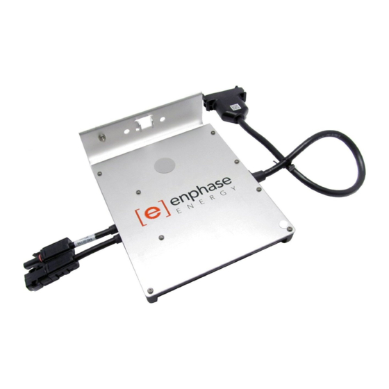
Microinverter (M215-60-230)
TM
Read and follow all warnings and instructions in the M215 Installation and Operation Manual at
http://www.enphase.com before using this document.
The microinverters will not produce power until the Envoy
with an appropriate grid profile. For instructions, refer to the Envoy Installation and Operation Manual at
http://www.enphase.com.
Measure AC Voltage at the Electricity Network Connection
1
Check all phase conductors: line to neutral and line to line.
Acceptable ranges are shown in
Step Details on back.
Position the Engage™ Cable
2
a. Lay out the cabling along the installed mounting rail for the AC branch circuit.
b. Install an AC branch circuit junction box at a suitable location on the mounting rail.
See notes in Step Details on back.
Check the drop
connector labels to
be sure that you have
the right cable.
You must use 3G2.5
cable for single-phase
or 5G2.5 cable for
three-phase.
volt meter
set to ACV
Communications Gateway is installed and configured
TM
Electrical distribution
board
drop
connector
®
Engage
Cable
Publicité

Manuels Connexes pour Enphase Energy M215


Sommaire des Matières pour Enphase Energy M215
- Page 1 Installing the M215 Microinverter (M215-60-230) Read and follow all warnings and instructions in the M215 Installation and Operation Manual at http://www.enphase.com before using this document. The microinverters will not produce power until the Envoy Communications Gateway is installed and configured with an appropriate grid profile.
-
Page 2: Quick Install Guide
M215 Microinverter Quick Install Guide Attach the Microinverters to the Rail Connect the Microinverters a. Mark the approximate centers of each PV a. Remove and discard the temporary module on the mounting rail. See notes in shipping cap from the cable connector Step Details on back. - Page 3 Connect the Cable to the AC Terminate the Unused End of the Cable Junction Box a. Remove 60mm of the cable sheath from the conductors. Connect the Engage Cable to the AC branch circuit junction box. See notes in Step Details on back. b.
- Page 4 Disconnect tool The LED on the underside of each WARNING: Install sealing caps M215 will blink green six times to on all unused AC connectors as they become live when the system indicate successful connection two is energised.
- Page 5 Important Safety Information This document contains important instructions for use during installation and maintenance of the Enphase M215™ Microinverter. To reduce the risk of electrical shock, and to ensure the safe installation and operation of the Enphase Microinverter, the following safety symbols appear throughout this docu- ment to indicate dangerous conditions and important safety instructions.
- Page 6 AVERTISSEMENT : Notez que AVVISO: L’M215 presenta punti di WARNUNG: Der M215 arbeitet mit einer adjustable voltage and frequency trip le M215 a des valeurs limites de intervento di tensione e frequenza am Installationsort einstellbaren Span- points that you must set before the tension et de fréquence réglables...
- Page 7 ⚠ WARNING: Do not mount the micro- AVERTISSEMENT : n’installez pas AVVISO: non montare il microinver- WARNUNG: Befestigen Sie den Mik- inverter in a location that allows long- le micro-onduleur dans un emplace- ter in una posizione che favorisca rowechselrichter nicht an einer Stelle mit term exposure to direct sunlight (i.e., ment où...
- Page 8 Kappe und dem Gehäuse at an angle, check that this angle Si vous installez le M215 dans un ter. Se l’M215 è installato con una des Mikrowechselrichters führen kann. does not allow for collection of water angle, vérifiez que cet angle ne...
-
Page 9: Plan D'installation
® Installation map • Peel the removable serial number label from each microinverter and affix it to the respective location on the installation map. • Peel the label from the Envoy and affix it to the installation map. • Log in to Enlighten. • Scan the installation map and upload it to the Activation form online. • Use Array Builder to create the virtual array using the installation map as your reference. • To see the array builder demo, go to http://enphase.com/support/videos. Plan d’installation • Décollez l’étiquette détachable comportant le numéro de série de chaque micro-onduleur et collez-la à l’emplacement correspondant sur la copie papier du plan de calepinage. • Retirez cette étiquette de l’Envoy et placez-la sur le plan de calepinage. • Connectez-vous à Enlighten. • Numérisez le plan de calepinage et téléchargez-le dans le formulaire d‘activation en ligne. • Utilisez l’Éditeur de champ PV pour créer le champ virtuel et utilisez le plan de calepinage en référence. • Pour consulter la démo de l’Éditeur de champs photovoltaïque, reportez-vous à http://enphase.com/support/videos. Mappa installazione • Rimuovere l’etichetta del numero di serie da ciascun microinverter e apporla nella posizione corrispondente sulla copia cartacea della mappa dell’impianto. • Rimuovere l’etichetta da Envoy e attaccarla sulla mappa dell’impianto. • Accedere a Enlighten. • Eseguire la scansione della mappa dell’installazione e uploadarla nel modulo di attivazione online di Enlighten. • Utilizzare il Configuratore di Matrici per creare il campo fotovoltaico virtuale. Usare la mappa di installazione come riferimento. • Per visualizzare una demo del Configuratore di Matrici, consultare http://enphase.com/support/videos. - Page 10 Envoy serial label / étiquette de numéro de série / PLAN D’INSTALLATION etichette di serie Envoy MAPPA INSTALLAZIONE Serien Nummer: ENPHASE.COM INSTALLATIONSPLAN To sheet / Vers la page / Al foglio / Zu Blatt: ________ © 2012 Enphase Energy Inc. All rights reserved.