Table des Matières
Publicité
Liens rapides
For mounting the scanning head, please refer to the separate Mounting Instructions.
Für Montage des Abtastkopfes bitte separate Anleitung beachten.
Pour le montage de la tête captrice, veuillez tenir compte des instructions distinctes.
Per il montaggio della testina fare riferimento al relativo manuale.
Tener en cuenta las instrucciones suministradas por separado para el montaje de la regla.
Mounting Instructions
Montageanleitung
Instructions de montage
Istruzioni di montaggio
Instrucciones de montaje
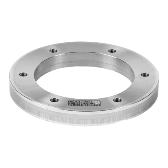
TTR ECA 4402
Scale Drum
Teilungstrommel
Tambour gradué
Tamburo graduato
Tambor de graduación
12/2015
Publicité
Table des Matières

Sommaire des Matières pour HEIDENHAIN TTR ECA 4402
- Page 1 Mounting Instructions Montageanleitung Instructions de montage Istruzioni di montaggio Instrucciones de montaje TTR ECA 4402 Scale Drum For mounting the scanning head, please refer to the separate Mounting Instructions. Teilungstrommel Für Montage des Abtastkopfes bitte separate Anleitung beachten. Tambour gradué...
-
Page 2: Table Des Matières
Contents Page Seite Inhalt Warnings Warnhinweise Sommaire Dimensions Abmessungen Indice General notes on the centering procedure Allgemeine Hinweise für die Zentrierung 10 Mounting 10 Montage Indice Page Pagina Página Recommandations Avvertenze Advertencias Dimensions Dimensioni Dimensiones Remarques générales relatives au centrage Istruzioni generali di centraggio Indicaciones generales para el centraje 10 Montage... -
Page 3: Recommandations
Warnings Warnhinweise Recommandations Avvertenze Advertencias Note: – Mounting and commissioning is to be conducted by a qualified specialist under compliance with local safety regulations. – The system must be disconnected from power! – All mounting surfaces must be clean and free of burrs. The specified shaft tolerances must be complied with. –... - Page 4 Attention : – Le montage et la mise en service doivent être assurés par un personnel qualifié dans le respect des consignes de sécurité locales. – L ’installation doit être hors tension ! – Toutes les surfaces de montage doivent être propres et exemptes de bavures. Les tolérances spécifiées pour l‘arbre doivent être respectées. –...
-
Page 5: Dimensions
Dimensions Abmessungen Dimensions Dimensioni Dimensiones Bearing Lagerung Roulement Cuscinetto Rodamiento 6x/12x/18x ¬ 0.2 A 0.1 A 0.05 A... - Page 6 Internal mating diameter (shaft) Aufnahmedurchmesser (Welle) Diamètre de montage (arbre) Æ 70 +0.07/+0.05 Æ † 70 Æ 85 Æ 104.63 6x60° = 360° 6x M5 Diametro di supporto (albero) Æ 127.64 Æ 80 +0.07/+0.05 Æ † 80 Æ 95 6x60° = 360° 6x M5 Diámetro de alojamiento (eje) Æ...
-
Page 7: Remarques Générales Relatives Au Centrage
General notes on the centering procedure Allgemeine Hinweise für die Zentrierung Remarques générales relatives au centrage Istruzioni generali di centraggio Indicaciones generales para el centraje Recommended centering encoder: Capacitive sensor Empfehlung für Zentrier-Messgerät: Kapazitiver Sensor Préconisé pour le système de mesure de centrage : Capteur capacitif Raccomandazione per sistema di misura di centraggio: Sensore capacitivo... - Page 8 Alternative: Length gauge Alternative: Messtaster Alternative : oder Palpeur de mesure In alternativa: Tastatore di misura Alternativa: Palpador de medida Caution: The length gauge must not touch the incremental track or reference-mark track! Achtung: Taster darf Inkremental- und Code Spur nicht berühren! Attention : Le palpeur ne doit pas toucher la piste incrémentale ni celle des marques de référence ! Attenzione: il tastatore non deve toccare la traccia incrementale e di riferimento.
- Page 9 E = 0.67 · D max Resulting eccentricity of the scale drum in [µm]. ∆ Max. difference between the values measured at the 3 marks in [µm]. resultierende Exzentrizität der Teilungstrommel in [µm]. maximale Differenz der Messwerte an den 3 Markierungen in [µm]. exzentricité...
-
Page 10: Montaje
Mounting Montage Montage Montaggio Montaje The scale drum is pre-centered by the customer shaft. The three holes located near the marks M on the outside diameter are used for mounting. The ID label T must be visible. Die Teilungstrommel wird durch die Kundenwelle vorzentriert. Für die Befestigung werden die drei Bohrungen verwendet, welche sich in der Nähe der Markierungen M am Außendurchmesser befinden. - Page 11 Tighten the screws. Schrauben festziehen. Serrer les vis. Serrare le viti. Apretar los tornillos. = 0.1 Nm ISO 7092 – 6/5/3 – 140HV - A2 ISO 4762 – M6 x 20/M5x20/M3x20 – A2...
- Page 12 The three marks on the circumference of the scale drum are used for final E = 0.67 · D max centering. Make sure to position the centering encoder at the center of each mark. = ± 412 Die endgültige Zentrierung erfolgt mit Hilfe der drei Markierungen am ¬...
- Page 13 In order to avoid damage to the scale drum: Tap lightly For protruding customer shaft – Only tap on the inside of the ridge (or use an auxiliary pin for a protruding Leicht klopfen bei vorstehender Kundenwelle customer shaft) Tapoter légèrement avec arbre moteur dépassant –...
- Page 14 Tighten the first three screws incrementally. Die drei ersten Schrauben schrittweise anziehen. Serrer graduellement les trois premières vis. Serrare gradualmente le prime tre viti. Apretar gradualmente los tres primeros tornillos. ISO 4762 – A2 – M3 ISO 4762 – A2 – M5 ISO 4762 –...
- Page 15 Also tighten the other screws incrementally. Die restlichen Schrauben ebenfalls schrittweise anziehen. Serrer également les vis restantes de manière progressive. Serrare quindi gradualmente le viti restanti. Asimismo, apretar gradualmente los tornillos restantes. ISO 4762 – A2 – M3 ISO 4762 – A2 – M5 ISO 4762 –...
- Page 16 1125430-02 1125430–01–A–01 · Printed in Germany · 1/2016 · H...


