Table des Matières
Publicité
Les langues disponibles
Les langues disponibles
Liens rapides
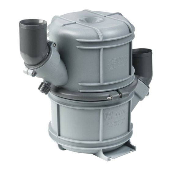
Waterlock
Waterlock
Wassersammler
Waterlock
Colector
Marmitte
C o p y r i g h t © 2 0 0 1 , 2 0 0 4 Ve t u s d e n O u d e n n . v. S c h i e d a m H o l l a n d
Installatie instructies
Installation instructions
Installationsvorschriften
Instructions d'installation
Instrucciones de instalación
Istruzioni per l'installazione
NEDERLANDS
ENGLISH
DEUTSCH
FRANÇAIS
ESPAÑOL
ITALIANO
NLP
2
4
6
8
10
12
Publicité
Table des Matières

Sommaire des Matières pour Vetus NLP Série
- Page 1 Installatie instructies Installation instructions Installationsvorschriften Instructions d’installation Instrucciones de instalación Istruzioni per l’installazione NEDERLANDS ENGLISH DEUTSCH FRANÇAIS ESPAÑOL ITALIANO Waterlock Waterlock Wassersammler Waterlock Colector Marmitte C o p y r i g h t © 2 0 0 1 , 2 0 0 4 Ve t u s d e n O u d e n n . v. S c h i e d a m H o l l a n d...
-
Page 2: Installatie
‘inklappen’. De uitlaatleiding van waterlock naar spiegeldoorvoer moet zo Vetus uitlaatslang voldoet aan alle hiervoor gestelde eisen. worden geïnstalleerd dat: - Het hoogste punt in de uitlaatleiding zich niet meer dan 150 cm boven de onderzijde van de waterlock bevindt. - Page 3 NEDERLANDS Slangaansluitingen Installatievoorbeelden Om de slangen optimaal op de waterlock te kunnen aansluiten Afgebeeld op blz. 15 zijn uitlaatsystemen met een waterlock, zijn beide slangaansluitingen 360° draaibaar. type NLP , een geluiddemper type MP , een zwanenhals type LT en een uitlaatspiegeldoorvoer. NLP40/45/50 De inloop van achteropkomend water wordt vrijwel volledig voorkomen door het extra hoogteverschil in de zwanenhals.
- Page 4 Introduction Installation The Vetus exhaust system components are especially suitable Installing waterlock NLP for use in water-injected exhaust systems. Instal the waterlock as vertical as possible. The maximum continuous operating temperature of the plastic The waterlock ‘IN’-connection must always remain below the...
-
Page 5: Installation Examples
ENGLISH Hose connections Installation Examples In order to achieve the ideal connection between the hoses and Exhaust systems with a waterlock type NLP , silencer type MP , the waterlock, both hose connections turn through 360 goose neck type LT and a transom connection are shown on degrees. -
Page 6: Montage
Einleitung Montage Die Teile der Vetus-Auspuffsysteme eignen sich ausschließlich Aufstellung Wassersammler NLP für die Verwendung in wassereingespritzten Auspuffsystemen. Stellen Sie den Wassersammler möglichst vertikal auf. Die maximale Dauerbetriebstemperatur der Kunststoffteile der Der ‘IN’-Anschluß des Wassersammlers muß sich immer unter Auspuffsysteme beträgt 70 ºC. - Page 7 DEUTSCH Schlauchverbindungen Montagebeispiele Beide Schlauchverbindungen sind um 360˚ drehbar, um die Auf S. 15 sind Auspuffsysteme mit einem Wassersammler Typ Schlaüche optimal an den Wassersammler anschließen zu NLP , ein Schalldämpfer Typ MP , ein Schwanenhals Typ LT und können. eine Auspuffspiegeldurchführung abgebildet.
- Page 8 - Le point le plus élevé de la tuyauterie ne doit pas être situé à plus de 150 cm au-dessus de la partie inférieure du water- Le tuyau d’échappement Vetus répond à toutes ces exigences. lock. - La longueur de cette partie de tuyauterie, entre le waterlock AVERTISSEMENT et le point le plus élevé, ne doit pas dépasser 300 cm.
-
Page 9: Exemples D'installation
FRANÇAIS Raccordements de tuyau Exemples d’installation Pour assurer un raccord parfait des tuyaux sur le waterlock, les Les pièces représentées à la page 15 sont des systèmes deux raccordements de tuyau peuvent tourner de 360˚. d’échappement avec un waterlock, type NLP , un silencieux type MP , un col de cygne type LT et une sortie d’échappement. - Page 10 Introducción Instalación Las piezas de sistemas de escape Vetus son indicadas exclusi- Ubicación colector NLP vamente para aplicación en sistemas de escape con inyección El colector se ha de ubicar lo más vertical posible. de agua. ¡La conexión de ‘ENTRADA’ (‘IN’) del colector ha de quedarse La temperatura de funcionamiento continua máxima de las pie-...
-
Page 11: Ejemplos De Instalación
ESPAÑOL Conexiones de manguera Ejemplos de instalación Con la finalidad de poder conectar de forma óptima las man- En la pág. 15 se representan sistemas de escape con un colec- gueras en el colector, ambas conexiones de manguera se pue- tor, tipo NLP , un silenciador tipo MP , un sifón tipo LT y un con- den girar 360˚. - Page 12 Montarlo dunque utilizzando i tiranti in dotazione. Il tubo di scarico Vetus soddisfa tutti i suddetti requisiti. La conduttura di scarico dal marmitte di scarico all’uscita di poppa deve essere installata in modo tale che: ATTENZIONE - Il punto più...
-
Page 13: Esempi Di Installazione
ITALIANO Raccordi del tubo Esempi di installazione Per allacciare in modo ottimale i tubi di gomma al marmitta, A pag. 15 sono rappresentati i sistemi di scarico con un ambedue i raccordi sono girevoli a 360°. Marmitte, tipo NLP , un silenziatore tipo MP , un collo d’anatra tipo LT e un’uscita di scappamento di poppa. - Page 14 Hoofdafmetingen Hauptabmessungen Dimensiones principales Principal dimensions Dimensions principales Dimensioni principali NLP40 / NLP45 / NLP50 Volume: 4,5 l (1.00 Imp. Gal., 1.19 U.S.Gal.) ø 40 mm (1.57”) ø 45 mm (1.77”) ø 50 mm (1.97”) NLP50S / NLP60 / NLP75 / NLP90 Volume: 10 l (2.20 Imp.
- Page 15 Installatievoorbeeld Montagebeispiel Ejemplo de instalación Installation example Exemple d’installation Esempio di installazione 1 & 2: Uitlaatsystemen met waterinjectiepunt ‘C’ 15 cm of meer boven de waterlijn Exhaust systems with water-injection point ‘C’ 15 cm or more above the waterline Auspuffsystemen mit Wasserein-spritzpunkt ‘C’...
- Page 16 FOKKERSTRAAT 571 - 3125 BD SCHIEDAM - HOLLAND - TEL.: +31 10 4377700 - TELEX: 23470 TELEFAX: +31 10 4372673 - 4621286 - E-MAIL: sales@vetus.nl - INTERNET: http://www.vetus.nl Printed in the Netherlands 3.0419 I.NLP 08-01 Rev. 03-04...


