Table des Matières
Publicité
Les langues disponibles
Les langues disponibles
Liens rapides
WWW.BROAN.COM
WWW.BROAN.CA
WWW.NUTONE.CA
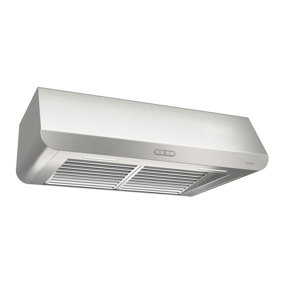
RANGE HOOD
Series: EPLEC1 and NPLEC1
INSTALLATION, USE
AND CARE MANUAL
English - See page 2
HOTTE
DE CUISINIÈRE
Séries : EPLEC1 et NPLEC1
MANUEL D'INSTALLATION,
D'UTILISATION ET D'ENTRETIEN
Français - Voir en page 27
CAMPANA
DE COCINA
Series: EPLEC1 y NPLEC1
MANUAL DE INSTALACIÓN,
USO Y CUIDADO
Español - Vease la pagína 60
Serial number:
99045656-003A
Publicité
Chapitres
Table des Matières

Manuels Connexes pour Broan-NuTone EPLEC1 Série


Sommaire des Matières pour Broan-NuTone EPLEC1 Série
- Page 1 WWW.BROAN.COM WWW.BROAN.CA WWW.NUTONE.CA RANGE HOOD Series: EPLEC1 and NPLEC1 INSTALLATION, USE AND CARE MANUAL English - See page 2 HOTTE DE CUISINIÈRE Séries : EPLEC1 et NPLEC1 MANUEL D’INSTALLATION, D’UTILISATION ET D’ENTRETIEN Français - Voir en page 27 CAMPANA DE COCINA Series: EPLEC1 y NPLEC1 MANUAL DE INSTALACIÓN, USO Y CUIDADO...
-
Page 2: Table Des Matières
Safety ....... . . 3-4 Operation ....... 5 Cleaning and Maintenance . - Page 3 READ AND SAVE THESE INSTRUCTIONS Intended for domestic cooking only INSTALLER: LEAVE THIS MANUAL WITH HOMEOWNER. For Broan Elite products in U.S.A., register your range hood online at www.broan.com For Broan Elite products in Canada, register your range hood online at www.broan.ca For NuTone products in Canada, register your range hood online at www.nutone.ca WARNING TO REDUCE THE RISK OF FIRE, ELECTRIC SHOCK, OR INJURY TO...
- Page 4 WARNING TO REDUCE THE RISK OF A RANGE TOP GREASE FIRE: a) Never leave surface units unattended at high settings. Boilovers cause smoking and greasy spillovers that may ignite. Heat oils slowly on low or medium settings. b) Always turn hood ON when cooking at high heat or when flambeing food (i.e.: Crêpes Suzette, Cherries Jubilee, Peppercorn Beef Flambé).
-
Page 5: Operation
Operation Always turn your hood on before you begin cooking to establish an air flow in the kitchen. Let the blower run for a few minutes to clear the air after you turn off the range. This will help keep the whole kitchen cleaner and fresher. Operate the hood as follows: EPLEC1 NPLEC1 SERIES... -
Page 6: Cleaning And Maintenance
Cleaning and Maintenance Proper maintenance of the Range Hood will assure proper performance of the unit. MOTORS The motors are permanently lubricated and never need oiling. If the motor bearings make excessive or unusual noise, replace the motor with the exact service motor. The fan wheel should also be replaced. -
Page 7: Installation
For ADA compliance installation guidelines, please visit www.broan-nutone.com Recommended Tools and Accessories for Installation • Measuring tape • Phillips screwdriver no. 2 • Nut driver or socket 11/32” • Flat blade screwdriver (to open knockout holes) • Drill, 1/8” drill bit and 1½” hole saw (to mark holes for ducting and cut electrical access hole) •... - Page 8 Contents Before proceeding to the installation, check the contents of the box. If items are missing or damaged, contact the manufacturer. Make sure that the following items are included: (1) 7” R (1) 3¼” 10” (1) 3¼” 14” OUND AMPER SSEMBLY AMPER SSEMBLY...
-
Page 9: Prepare The Hood
Prepare the Hood 1 ] If present, remove all protective polyfilm from the hood and/or parts. 2 ] Using the finger cup, remove the grease filters from the hood by pushing down and tilting filters out 3 ] Remove both fillers by removing the 3 screws holding each one of them. Slide each one towards the center of the hood and tilt it up to remove it completely. - Page 10 4 ] Remove the screw holding the 3¼” x 10” adapter/damper as well as the one for the 3¼” x 14” adapter/damper, remove their tape strips and and put the adapter/dampers aside. Save these screws, they will be used later to hold the blower cover plate. 5 ] Remove both tape strips holding the 7”...
- Page 11 8 ] Remove the EZ1 brackets from inside the hood by cutting off the tie wrap. Discard the tie wrap. BRACKETS 9 ] Remove Electrical Power Cable Knockout from top (vertical exhaust) or back (horizontal exhaust) of hood. For knockout removed from back of hood, install an appropriate strain relief, 1/2”...
- Page 12 3¼” x 14” DUCTED INSTALLATION ONLY 12 ] Remove 3¼” x 14” vertical or 3¼” x 14” horizontal knockout plate as appropriate for your ducting method (see F 1 A and 1 B). IGURES IGURE IGURE 3¼” 14” VERTICAL KNOCKOUT PLATE 3¼”...
- Page 13 3¼” x 10” OR 7” ROUND DUCTED INSTALLATION ONLY 12 ] Remove 3¼” x 10” vertical, 3¼” x 10” horizontal (both are the rectangular central knockout plates, see hatched areas) or 7-inch round knockout plate as appropriate for your ducting method (see F 1 A and 1 B).
-
Page 14: Prepare The Hood Location
Prepare the Hood Location NOTE: Before starting installation, read all the steps of these instructions. Use the illustration below to identify your kitchen cabinet type. FRAMED CABINET FRAMELESS CABINET This manual covers 2 kinds of installation: the standard (without EZ1 brackets) and the EZ1 one-person installation system (using included template and brackets). - Page 15 4 ] Drill a 1/8” dia. pilot hole for house wiring, at B location on template. 5 ] Use a sharp pencil or 1/8” drill bit to mark the locations for the appropriate duct access holes (16 locations for 7” round duct, or 4 corner locations for rectangular duct). Remove the template.
- Page 16 FRAMELESS CABINET Refer to the marking on brackets to determine the correct installation side and orientation. 7/64” Align the corresponding bracket to the cabinet side, while placing rear end of bracket against the wall. Draw a line on the outer edge of the bracket (as shown). ...
-
Page 17: Install The Hood (Ez1 Bracket)
Install the Hood (EZ1 Bracket) OTE: The following procedure applies to both frame or frameless cabinet installations. 1 ] Run house power cable between service panel and hood location. 2 ] There are 2 pairs of recessed holes on each side of the top of the hood (on rear: A and B, on front C and D on illustration below);... - Page 18 7 ] For framed cabinet, secure the hood to the EZ1 brackets using a 10” screwdriver bit and 4 no. 8-18 x 1/2” metal screws with washers (screws and washers included in parts bag). Insert 2 screws and washers per side, in the slots (as shown in inset on illustration below). 8 ] For frameless cabinet, secure the hood to the cabinet using a 10”...
-
Page 19: Standard Installation
Standard Installation (without EZ1 brackets) 1 ] Use the proper diagram below for placement of ductwork and electrical cutout in cabinet or wall. For a non-ducted installation, DO NOT cut a duct access hole, only cut the hole for electrical wiring. CENTER LINE 3¼"... -
Page 20: Install The Hood (Standard Installation)
Install the Hood (Standard Installation) OTE: Two installers are recommended because of the weight of this hood. 1 ] Run house power cable between service panel and hood location. For hood with power cable access located on back of hood, run the house power cable into the hood through the strain relief previously installed in step 9 on page 11. -
Page 21: Connect The Wiring
Connect the Wiring WARNING Risk of electric shock. Electrical wiring must be done by qualifi ed personnel in accordance with all applicable codes and standards. Before connecting wires, switch power off at service panel and lock service disconnecting means to prevent power from being switched on accidentally. -
Page 22: Install The Filters
Install the Filters Ducted Installation Only: Re-install grease filters removed in step 2 , page 9, under “Prepare the Hood” . Non-ducted Installation Only: Purchase two non-ducted filters from your local distributor or retailer (see product specification label for filter type). Attach the non-ducted filters following instructions packed with the non- ducted filters. - Page 23 EPLEC1 AND NPLEC1 SERIES...
- Page 24 ARTS AND EPAIRS In order to ensure your unit remains in good working condition, you must use Broan-NuTone LLC or Broan-NuTone Canada ULC genuine replacement parts only. Broan-NuTone LLC or Broan-NuTone Canada ULC genuine replacement parts are specially designed for each unit and are manufactured to comply with all the applicable certification standards and maintain a high standard of safety. Any third party replacement part used may cause serious damage and drastically reduce the performance level of your unit, which will result in premature failing.
- Page 25 EPAIRS In order to ensure your unit remains in good working condition, you must use Broan-NuTone Canada ULC genuine replacement parts only. Broan-NuTone Canada ULC genuine replacement parts are specially designed for each unit and are manufactured to comply with all the applicable certification standards and maintain a high standard of safety.
-
Page 26: Warranty
Limited Warranty Warranty Period and Exclusions: Broan-NuTone LLC and Broan-NuTone Canada ULC (either being the “Company”) warrants to the original consumer purchaser of its product (“you”) that the product (the “Product”) will be free from material defects in the Product or its workmanship for a period of one (1) year from the date of original purchase (or such longer period as may be required by applicable law). - Page 27 Sécurité ......28-29 Fonctionnement ......30 Nettoyage et entretien .
-
Page 28: Veuillez Lire Et Conserver Ces Directives
VEUILLEZ LIRE ET CONSERVER CES DIRECTIVES Conçues pour usage domestique seulement INSTALLATEUR : LAISSER CE MANUEL AU PROPRIÉTAIRE. Pour une hotte Broan aux États-Unis, enregistrez votre hotte en ligne à www.broan.com Pour une hotte Broan au Canada, enregistrez votre hotte en ligne à www.broan.ca Pour une hotte NuTone au Canada, enregistrez votre hotte en ligne à... - Page 29 AVERTISSEMENT AFIN DE RÉDUIRE LES RISQUES DE FEU DE CUISINIÈRE : Ne jamais laisser les appareils de cuisson sans surveillance lorsqu’ils sont réglés à feu vif. Les débordements engendrent de la fumée et des déversements graisseux pouvant s’enflammer. Chauffez l’huile lentement, à feu doux ou moyen. Mettez toujours la hotte en marche lorsque vous cuisinez à...
-
Page 30: Fonctionnement
Fonctionnement Toujours mettre en marche la hotte avant de commencer la cuisson afin d’établir une circulation d’air dans la cuisine. Laisser également la hotte fonctionner quelques minutes après l’arrêt de la cuisinière afin de nettoyer l’air. Cela aidera à maintenir la cuisine plus propre et plus fraîche. Faire fonctionner la hotte comme suit : SÉRIES EPLEC1 NPLEC1... -
Page 31: Nettoyage Et Entretien
Nettoyage et entretien L’entretien adéquat de la hotte préservera ses performances. MOTEURS Les moteurs sont lubrifiés en permanence et n’ont pas besoin d’être huilés. Si les roulements de moteur sont anormalement bruyants, remplacer le moteur uniquement par le même modèle. La roue du ventilateur doit aussi être remplacée. -
Page 32: Installation
Pour connaître les lignes directrices de l’ADA (Americans with Disabilities Act) concernant l’installation, veuillez visiter www.broan-nutone.com Matériel requis pour l’installation • Ruban à mesurer • Tournevis Phillips n° 2 • Tourne-écrou ou douille de 11/32 po • Tournevis à lame plate (pour dégager les ouvertures préamorcées) •... - Page 33 Contenu Avant de procéder à l’installation, vérifier le contenu de la boîte. Si des articles sont manquants ou endommagés, contacter le manufacturier. S’assurer que les articles suivants sont inclus : (1) A (1) A (1) P DAPTATEUR VOLET DAPTATEUR VOLET LAQUE POUR 3¼...
-
Page 34: Préparation De La Hotte
Préparation de la hotte 1 ] Retirer toute pellicule de plastique protectrice sur la hotte et/ou ses pièces. 2 ] Enlever les filtres à graisses en insérant un doigt dans la prise concave de chaque filtre, puis en poussant vers l’arrière de la hotte et en les basculant 3 ] Retirer les deux bandes de remplissage en retirant les 3 vis retenant chacune d'entre elles. - Page 35 4 ] Retirer la vis retenant l'adaptateur/volet de 3¼ po x 10 po et celle retenant l'adaptateur/volet de 3¼ po x 14 po, décoller les bandes de ruban adhésif et mettreles adaptateurs/volets de côté. Conserver ces vis puisqu'elle serviront plus tard à retenir le couvercle du ventilateur.
- Page 36 8 ] Détacher les supports EZ1 de l’intérieur de la hotte en coupant leur attache autobloquante. Se défaire de celle-ci. SUPPORTS EZ1 9 ] Retirer l’ouverture préamorcée du câble d’alimentation électrique du dessus (évacuation verticale) ou de l’arrière de la hotte (évacuation horizontale). Pour une ouverture préamorcée retirée de l’arrière de la hotte, installer un serre-fils approprié...
- Page 37 INSTALLATION AVEC CONDUITS DE 3¼ po x 14 po SEULEMENT 12 ] Retirer les ouvertures préamorcées de 3¼ po x 14 po verticale ou de 3¼ po x 14 po horizontale, selon le mode d’évacuation choisi (voir les F 1 A et 1 B). IGURES IGURE IGURE...
- Page 38 INST. AVEC CONDUITS DE 3¼ po x 10 po OU 7 po ROND SEULEMENT 10 ] Retirer les ouvertures préamorcées de 3¼ po x 10 po verticale, 3¼ po x 10 po horizontale (les 2 étant les plaques rectangulaires centrales, voir les zones hachurées), ou 7 po ronde selon le mode d’évacuation choisi (voir les F 1 A et 1 B).
-
Page 39: Préparation De L'emplacement De La Hotte
Préparation de l’emplacement de la hotte NOTE : Avant de commencer l’installation, veuillez lire toutes les étapes de cette instruction. Identifier votre type d’armoire de cuisine à l’aide de l’illustration ci-dessous. ARMOIRE À FOND EN RETRAIT ARMOIRE À FOND ÉGAL Ce manuel couvre deux types d’installation : l’installation standard (sans les supports EZ1) et le système d’installation par une personne EZ1 (en utilisant le gabarit et les supports inclus). - Page 40 4 ] Percer un avant-trou de 1/8 po de diamètre pour le câble d’alimentation, à l’emplacement B sur le gabarit. 5 ] Utiliser un crayon pointu ou un foret de 1/8 po pour marquer les repères du trou pour le conduit approprié (16 endroits pour le conduit rond de 7 po, ou aux 4 coins pour les conduits rectangulaires).
- Page 41 ARMOIRE À FOND ÉGAL Voir les inscriptions sur les supports pour les installer dans le bon sens (inscriptions en anglais seulement : front = avant, left = gauche, lean on rear wall = appuyer sur le mur arrière). 7/64 po ...
-
Page 42: Installation De La Hotte (Avec Supports Ez1)
Installation de la hotte (avec supports EZ1) OTE : La procédure convient autant pour les armoires à fond en retrait qu'à fond égal. 1 ] Acheminer le câble d’alimentation depuis le panneau de distribution de la maison jusqu’à l’emplacement de la hotte. 2 ] De chaque côté... - Page 43 7 ] Pour une armoire à fond en retrait, à l'aide d'une perceuse munie d'un embout de tournevis de 10 po, fixer la hotte aux supports EZ1 à l’aide de 4 vis à métaux n° 8-18 x 1/2 po et 4 rondelles (vis et rondelles incluses dans le sac de pièces).
-
Page 44: Installation Standard
Installation standard (sans supports EZ1) 1 ] Utiliser le diagramme approprié ci-dessous pour déterminer l’emplacement exact des coupes à effectuer pour le conduit et le fil d’alimentation électrique dans l’armoire ou le mur. Pour une installation en recirculation, NE PAS découper de trou pour le conduit. LIGNE ÉVACUATION VERTICALE LIGNE... -
Page 45: Installation De La Hotte (Installation Standard)
Installation de la hotte (installation standard) OTE : Deux installateurs sont recommandés pour l’installation en raison du poids de cette hotte. 1 ] Acheminer le câble d’alimentation électrique du panneau de distribution jusqu’à l’emplacement de la hotte. Si l’ouverture pour le câble d’alimentation est à l’arrière de la hotte, insérer le câble d’alimentation dans la hotte à... -
Page 46: Branchement Électrique
Branchement électrique AVERTISSEMENT Risque d’électrocution. Le raccordement électrique doit être effectué par du personnel qualifi é conformément aux codes et aux standards en vigueur. Avant d’effectuer le branchement, coupez l’alimentation électrique au panneau de distribution et verrouillez-le pour éviter une mise en marche accidentelle. -
Page 47: Installation Des Filtres
Installation des filtres Installation avec conduits seulement : Remettre en place les filtres à graisses retirés à l’étape 2 en page 34 dans la section « Préparation de la hotte ». Installation en recirculation seulement : Se procurer un ensemble de filtres de recirculation chez un distributeur ou détaillant local (consulter l’étiquette de spécification pour connaître le type de filtre). - Page 48 SÉRIES EPLEC1 ET NPLEC1...
- Page 49 Leur remplacement par des pièces ne provenant pas de Broan-NuTone LLC ou de Broan-NuTone Canada ULC pourrait ne pas assurer la sécurité de l’appareil, entraîner une réduction sévère des performances ainsi qu’un risque de défaillance prématurée. Broan-NuTone LLC et Broan-NuTone Canada ULC recommandent également de toujours vous référer à...
- Page 50 IÈCE DE REMPLACEMENT ET SERVICE Pour assurer le bon fonctionnement de votre appareil, vous devez toujours utiliser des pièces d’origine provenant de Broan-NuTone Canada ULC. Les pièces d’origine de Broan-NuTone Canada ULC sont spécialement conçues pour satisfaire toutes les normes de certification de sécurité...
-
Page 51: Pièces De Rechange
Garantie limitée Période de garantie et exclusions : Broan NuTone LLC (la « Société ») ou Broan-NuTone Canada ULC et/ou son subsidiaire garantit au consommateur acheteur initial (« vous ») de son produit (le « Produit ») que celui-ci est exempt de tout vice de matériau ou de fabrication pour une période de un (1) an à... - Page 52 Seguridad ......53-54 Funcionamiento ......55 Limpieza y mantenimiento .
- Page 53 LEA ESTAS INSTRUCCIONNES Y GUÁRDELAS Exclusivamente para cocinas domésticas INSTALADOR: ENTREGUE ESTE MANUAL AL PROPIETARIO. En EE.UU., registre su Broan campana de cocina en línea en www.broan.com En Canadá, registre su Broan campana de cocina en línea en www.broan.ca En Canadá, registre su NuTone campana de cocina en línea en www.broan.ca ADVERTENCIA PARA REDUCIR EL RIESGO DE INCENDIO, DESCARGA ELÉCTRICA O LESIÓN CORPORAL, RESPETE LAS SIGUIENTES INDICACIONE:...
- Page 54 ADVERTENCIA PARA REDUCIR EL RIESGO DE QUE ARDA LA GRASA EN LA PARTE SUPERIOR DE LA COCINA: No deje nunca recipientes de cocina a fuego vivo sin vigilancia. Los desbordamientos producen humo y derrames grasientos que pueden inflamarse. Caliente el aceite despacio, a fuego lento o mediano. Ponga en marcha siempre la campana extractora al cocinar a temperaturas elevadas o al cocinar alimentos flameados (crepas Suzette, cerezas jubilee, res con pimienta flambeada).
-
Page 55: Funcionamiento
Funcionamiento Ponga la campana en marcha siempre antes de empezar a cocinar para crear una corriente de aire en la cocina. Deje funcionar el ventilador impelente varios minutos para limpiar el aire cuando ya haya apagado la cocina. De este modo, la cocina estará más limpia y despejada. Utilice la campana de la siguiente manera: SERIES EPLEC1 NPLEC1... -
Page 56: Limpieza Y Mantenimiento
Limpieza y mantenimiento El mantenimiento adecuado de la campana permitirá que funcione correctamente. MOTORES Los motores estan lubricados permanentemente y no necesitan engrase nunca. Si los rodamientos de uno motor hacen un ruido excesivo o no habitual, sustituya este motor por otro idéntico. -
Page 57: Herramientas Y Accesorios Recomendados Para La Instalación
Para las directrices de instalación conforme a la ADA, visite www.broan-nutone.com Herramientas y accesorios recomendados para la instalación • Cinta métrica • Destornillador Phillips n.° 2 • Destornillador para tuercas o un dado de 11/32” • Destornillador de punta plana (para abrir los orificios punzonados) •... - Page 58 Contenido Antes empezar la instalación, verifique el contenido de la caja. Si faltan elementos o hay elementos dañados, póngase en contacto con el fabricante. Compruebe que estén en la caja los siguientes elementos: 1) C 1) C 1) C ONJUNTO DE LA ONJUNTO DE LA ONECTOR CLAPETA DE RETENCIÓN...
-
Page 59: Prepare La Campana
Prepare la campana 1 ] De haberla, retire de la campana y de todas las piezas la película protectora. 2 ] Use el orificio de agarre para retirar de la campana los filtros de grasa empujando hacia abajo e inclinando los filtros hacia fuera 3 ] Retire las piezas de relleno quitando los 3 tornillos que sujetan cada una de ellas. - Page 60 4 ] Retire el tornillo que sujeta el adaptador/clapeta de retención de 3¼” x 10” y el tornillo que sujeta el adaptador/clapeta de retención de 3¼” x 14” , retire sus tira de cinta, y reserve los dos adaptador/clapeta de retención. Guarde estos tornillos ya que ellos volverán a usar después para sujetar la placa.
- Page 61 8 ] Retire los soportes EZ1 del interior de la campana cortando la tira de amarre. Deseche la tira de amarre. SOPORTES EZ1 9 ] Retire la parte punzonada para el cable de alimentación eléctrica desde la parte superior (salida vertical) o desde la parte trasera (salida horizontal) de la campana. Para la parte punzonada quitado desde la parte trasera de la campana, instale una descarga de presión adecuada de 1/2”...
- Page 62 INSTALACIÓN CON CONDUCTOS DE 3¼" x 14" ÚNICAMENTE 12 ] Retire la placa punzonada vertical de 3¼” x 14” o horizontal de 3¼” x 14” , según el modo de evacuación elegido (véanse las F 1 A y 1 B). IGURAS IGURA IGURA...
- Page 63 INST. CON CONDUCTOS DE 3¼” x 14” O 7” REDONDO ÚNICAMENTE 12 ] Retire la placa punzonada vertical de 3¼” x 10” , horizontal de 3¼” x 10” (ambos están las placas punzonadas rectangular centrales, veanse las zonas rayadas) o la placa punzonada redonda de 7 pulgadas, según el modo de evacuación elegido (véanse las F 1 A y 1 B).
-
Page 64: Prepare La Ubicación De La Campana
Prepare la ubicación de la campana NOTA: antes de empezar la instalación, lea todas las etapas de estas instrucciones. Use la ilustración de abajo para reconocer su tipo de armario de cocina. ARMARIO CON ARMAZÓN ARMARIO SIN ARMAZÓN Este manual cubre 2 tipos de instalación: la normal (sin soportes EZ1) y la instalación EZ1 por una persona (usando la plantilla y los soporte provistos). - Page 65 4 ] Taladre un orificio piloto de 1/8” de diámetro para el cableado de la vivienda, en el punto B de la plantilla. 5 ] Use un lápiz afilado o una broca de 1/8” para marcar los puntos para los orificios de acceso de los conductos (16 puntos para un conducto redondo de 7”...
- Page 66 ARMARIO SIN ARMAZÓN Consulte las marcas de los soporte para establecer el lado y la orientación correctos de la instalación (marcas en inglés solamente: front = parte delantera, left = izquierda, lean on rear wall = apoyar contra la pared trasera). 7/64”...
-
Page 67: Instale La Campana (Soporte Ez1)
Instale la campana (Soporte EZ1) OTA: El procedimiento siguiente se aplica a las instalaciones en armarios con armazón y sin armazón. 1 ] Lleve el cable de alimentación de la vivienda del tablero de servicio al lugar de la campana. 2 ] Hay 2 pares de orificios rebajados en cada lado de la parte superior de la campana (en la parte trasera: A y B, en la parte delantera C y D en la ilustración de abajo);... - Page 68 7 ] En los armarios con armazón, sujete la campana a los soportes EZ1 por medio de los cuatro (4) tornillos para metal n.° 8-18 x 1/2” y las arandelas (los tornillos y las arandelas vienen en la bolsa de piezas) con un taladro de 10” . Introduzca dos (2) tornillos (y las arandelas correspondientes) en cada lado, en las ranuras (como se ve en los detalles de la ilustración de abajo).
-
Page 69: Instalación Normal (Sin Soportes Ez1)
Instalación normal (sin soportes EZ1) 1 ] Use el diagrama adecuado de abajo para colocar los conductos y la alimentación eléctrica en el armario o en la pared. Para una instalación sin conductos, NO corte el orificio de acceso al conducto; corte sólo el orificio para el cableado eléctrico. EVACUACIÓN VERTICAL EVACUACIÓN VERTICAL LÍNEA CENTRAL... -
Page 70: Instale La Campana (Instalación Normal)
Instale la campana (Instalación normal) 1 ] Lleve el cable de alimentación de la vivienda del tablero de servicio al lugar de la campana. Si el orificio de acceso del cable alimentación de la campana este en su parte trasera, lleve el cable de alimentación de la vivienda a la campana a través de la descarga de presión instalada previamente en la etapa 9 en la página 61. -
Page 71: Conecte El Cableado
Conecte el cableado ADVERTENCIA Riesgo de descarga eléctrica. El cableado eléctrico debe hacerlo personal cualifi cado de acuerdo con los códigos y normas aplicables. Antes de conectar los hilos, corte la corriente en el tablero de servicio y bloquee éste para evitar que se ponga en marcha accidentalmente. HILO DE TIERRA DE LOS MOTORES TORNILLO... -
Page 72: Instale Los Filtros
Instale los filtros Instalación con conductos únicamente: Vuelva a instalar los filtros de grasa que quitó en la etapa 2 , en la página 59 (sección “Prepare la campana”). Instalación sin conductos únicamente: Compre dos filtros para instalación sin conductos a un distribuidor o minorista local (vea la etiqueta de especificaciones del producto para el tipo de filtro). - Page 73 SERIES EPLEC1 Y NPLEC1 73 73 73...
- Page 74 TEM NO MOSTRADO EPUESTOS Y REPARACIONES Para que el aparato esté en buenas condiciones, use sólo repuestos genuinos Broan-NuTone LLC o Broan-NuTone Canada ULC. 74 74 74 Los repuestos genuinos Broan-NuTone LLC o Broan-NuTone Canada ULC están diseñados especialmente para cada unidad y han sido fabricados para responder a las normas de certificación aplicables y mantener un alto nivel de seguridad.
- Page 75 Para que el aparato esté en buenas condiciones, use sólo repuestos genuinos Broan-NuTone Canada ULC. Los repuestos genuinos Broan-NuTone Canada ULC están diseñados especialmente para cada unidad y han sido fabricados para responder a las normas de certificación aplicables y mantener un alto nivel de seguridad. Los repuestos de otros fabricantes pueden dañar seriamente el aparato y reducir drásticamente su nivel de rendimiento, lo cual podría causar una falla prematura.
-
Page 76: Garantía
Garantía limitada Periodo y exclusiones de la garantía: Broan-NuTone LLC o Broan-NuTone Canada ULC (sea esta la “Compañía”) garantiza al consumidor comprador original de su producto (“usted”) que el producto (el “Producto”) estará libre de defectos en materiales o en mano de obra, por un periodo de un (1) año a partir de la fecha de compra original (o por un periodo mayor según sea requerido por la legislación aplicable).