Eurosystems M210 Manuel D'utilisation
Masquer les pouces
Voir aussi pour M210:
- Mode d'emploi (60 pages) ,
- Manuel d'utilisation (3 pages) ,
- Manuel d'utilisation (3 pages)
Publicité
Les langues disponibles
Les langues disponibles
Liens rapides
Bedienungsanleitung
für M210 Balkenmäher
Stand 01.06.2018
eurosystems Deutschland
Motorgeräte Handelsgesellschaft mbH
Im Fuchshau 14
D-73635 Rudersberg
Tel: +49 7183 / 30 590-0
Fax: +49 7183 / 30 590-20
info@eurosystems.info
www.eurosystems.info
Publicité

Manuels Connexes pour Eurosystems M210


Sommaire des Matières pour Eurosystems M210
- Page 1 Bedienungsanleitung für M210 Balkenmäher Stand 01.06.2018 eurosystems Deutschland Motorgeräte Handelsgesellschaft mbH Im Fuchshau 14 D-73635 Rudersberg Tel: +49 7183 / 30 590-0 Fax: +49 7183 / 30 590-20 info@eurosystems.info www.eurosystems.info...
- Page 6 Hände und Füße von den Schneidwerkzeugen Lesen Sie die Gebrauchsanweisung vor der Aufkleber Gashebel fernhalten! Inbetriebnahme. Etichetta acceleratore Non avvicinare mani e piedi agli utensili di taglio Leggere il manuale prima di usare la macchina. Label accelerator Keep hands and feet away from the blades! Read the instructions manual before operating Plaquette acceleration on the machine.
- Page 7 Übersetzung der originalen Betriebsanleitung Einleitung Verehrter Kunde, Inhaltsverzeichnis wir bedanken uns für Ihr Vertrauen, das Sie in unsere Qualitätsprodukte setzen und wünschen Ihnen viel Freude beim Arbeiten mit Ihrem neuen Gerät. Um eine zuverlässige Inbetriebnahme von vornherein zu gewährleisten, haben wir diese Betriebsanleitung geschaffen.
- Page 8 Drogen dürfen die Maschine nicht benutzen. 3 Diese Maschine ist entwickelt worden, damit sie von einem einzelnen ausgebildeten Benutzer verwendet werden kann. Der Benutzer des Geräts haftet für Schäden an anderen Personen oder an deren Sachgütern. Kontrollieren, dass andere Personen und insbesondere Kinder sich außerhalb des Arbeitsbereichs (10 mt.) aufhalten.
- Page 9 MONTAGE DES KABELS VOM GASHEBEL (Abb.2) Den am Motor angebrachten Hebel (1) in den Endanschlag bringen, wie gezeigt mit Pfeil “A” in der Abbildung. Den an der Sterze angebrachten Handgashebel (2) in den Endanschlag bringen, wie gezeigt mit Pfeil “B” in der Abbildung.
- Page 10 EINSTELLUNG MÄHBALKENHÖHE (Abb.7) Beim Mähen auf unebenen Böden ist die Höhe des Mähbalkens zu verstellen. Wie folgt vorgehen: die Schraubenmutter (1) lockern, den Gleitblock (2) in die gewünschte Stellung bringen und die Schraubenmutter spannen. Der Vorgang ist für beide Gleitblöcke durchzuführen. MESSEREINSTELLUNG (Abb.
- Page 11 Schleifkopf von 25 mm. Durchmesser und 35 mm Länge einzusetzen . Der Messerbalken ist mit dem Kopf der Schleifmaschine von der Stange bis zur Spitze des Schneidelements zu schärfen. Die Messerelemente sind mit einem Winkel von 25 Grad zu schärfen. DEMONTAGE DES OBERMESSERS (Abb.12) Schutzhaube entfernen Befestigungsschrauben (1) ausschrauben.
- Page 12 STÖRUNG Vor allen Wartungs- und Reinigungsarbeiten Zündkerzenstecker abziehen! Störung Beseitigung Motor springt nicht an Benzin auftanken Gashebel auf Position “START” stellen Zündkerzenstecker auf die Zündkerze aufstecken Zündkerze überprüfen, eventuell erneuern Kraftstoffhahn aufdrehen (nur für Motoren mit Kraftstoffhahn) Motorleistung lässt nach Luftfilter reinigen Unsauberer Schnitt Messerklingen nachschleifen / erneuern...
- Page 13 Istruzioni d’uso originali Introduzione Gentile cliente, la ringraziamo per la fiducia accordata ai ns. prodotti e le auguriamo un piacevole utilizzo Indice della sua macchina. Abbiamo creato queste istruzioni per I’uso allo scopo di assicurare, fin dall’inizio, un funzionamento privo d’inconvenienti. Seguite attentamente questi consigli, avrete la soddisfazione di possedere per molto tempo una macchina che funziona a dovere.
- Page 14 4 Esaminare accuratamente il terreno da falciare. Allontanare tutti i corpi estranei come pietre, bastoni, fili metallici , ossi dal terreno prima di iniziare le operazioni di falciatura. Lavorare solo alla luce del giorno, oppure in presenza di una buona illuminazione artificiale. 5 Non mettere in moto la macchina quando si è...
- Page 15 (3) nel foro (4), fissare la guaina (5) con l’apposito cavallotto (6) e bloccare con la vite (7). Attenzione : il manettino acceleratore in posizione “stop” deve spegnere il motore. MONTAGGIO CAVO COMANDO MARCIA (Fig.3) Il cavo di comando (1) è già collegato alla leva tendicinghia del telaio ed alla leva (2).
- Page 16 premi-lama tramite le viti (1) e il loro controdado. Per il controllo di ogni regolazione si deve dapprima smontare il cofano, poi fare ruotare lentamente con la mano la puleggia (2) e verificare che le lame si muovano liberamente. REGOLAZIONE LATERALE DEL MANUBRIO (Fig.14) Il manubrio della motofalciatrice è...
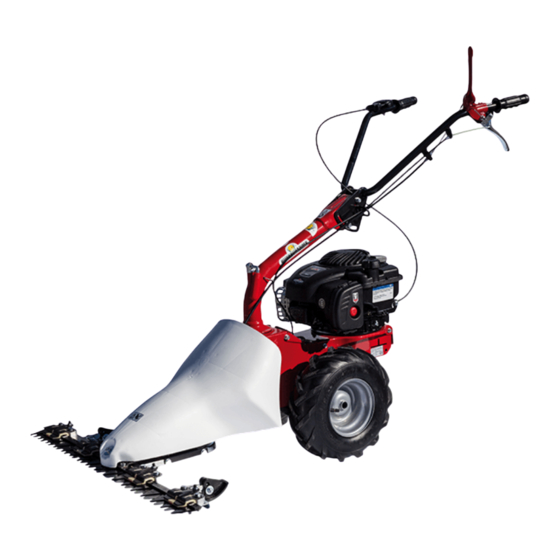
- Page 17 DESCRIZIONE (Fig. 13) 1) Manettino comando acceleratore - 2) Leva comando della trasmissione ruote motrici - 3) Leva comando innesto barra - 4) Motore - 5) Barra falciante - 6) Leva regolazione manubrio laterale - 7) Anello tenuta fili in acciaio. DATI TECNICI: Scartamento: 430 mm - Larghezza barra: 870 mm - Lunghezza complessiva: 1500 mm - Altezza complessiva: 1000 mm - Ruote: 2 pneumatici 13x5.00-6 - Massa: 60 kg.
- Page 18 Translation of original user instructions Introduction Dear Customer: List of contents Thank you for your confidence in purchasing our products. We wish you to enjoy using our machines. The following working instructions have been issued to ensure you a reliable running from the beginning. If you carefully follow such information the machine will operate with complete satisfaction have a long service life.
- Page 19 4 Carefully check the whole area to be mown. Remove all foreign objects, such as stones, sticks, wires, bones, etc. Use the mower only in daylight or if the working area is well illuminated. 5 Do not start the engine if anyone is standing in front of the cutter bar – the cutter and wheel drives must not be engaged. 6 Always mow across a slope.
- Page 20 ASSEMBLY CABLE FOR BAR CONNECTION (Fig.15) the cable is already linked to the black level placed under the frame and you need to make the cable to pass into the nib place on the side of the frame. Make the cable to pass into the steel ring of the handlebar support (fig.13 part.7) and into the nib hole (2) then into the red lever ( 4).
- Page 21 HANDLEBAR SIDE ADJUSTMENT (Fig. 14) The mower handlebar can be both side and height adjusted. It would be better before starting to work, to regulate the handlebar according to operator needs in order to make the machine easier to handle in every position. The side handlebar adjustment can be obtained on 3 different positions: please follow the steps: turn the lever anticlockwise (8) to detatch the clamping regulate the handle in the needed position.
- Page 22 TECHNICAL DATA Track: 430 mm. - Cutting bar width : 870 mm. – Total motor-mower length 1500 mm. – Total motor-mower height 1000 mm. – N°2 Tyres: 13x5.00-6 – Mass: 60 kg. For further technical data and details for the engine, please see the enclosed instructions manual. NOISE AND VIBRATION LEVEL Measured sound power level, Lwa = 94,2 dB (A), with a uncertainty value K = ±1,3 dB (A).
- Page 23 Traduction du mode d’emploi original Introduction Cher client, Table des matières nous vous remercions de la confiance que vous nous témoignez et vous souhaitons beaucoup de satisfaction dans son utilisation. Afin de garantir d’emblée un fonctionnement sans accrocs nous avons créé cette notice d’utilisation. Si Introduction vous observez exactement les indications suivantes votre appareil fonctionnera toujours à...
- Page 24 adolescents de moins de 16 ans ainsi que les personnes sous l’influence de l’alcool, de drogues ou de médicaments ne doivent en aucun cas utiliser l’appareil. 3) La machine a été projetée pour être utilisée par 1 seul opérateur compétent. L’utilisateur de l’appareil répond entièrement des dommages causés à...
- Page 25 MONTAGE DU CABLE DE L’ACCELERATEUR (Fig.2) Amener le levier (1) installé sur le moteur en fin de course comme indiqué par la flèche « A » sur la figure. Amener la manette de gaz (2) installée sur le mancheron en fin de course comme indiqué par la flèche « B » sur la figure.
- Page 26 Effectuer l’opérations sur les deux patins. REGLAGE DA LA LAME (Fig. 8) Après remplacement d’un lame ou après quelques heures de travail, il est indispensable de régler les guide-lame ou moyen des vis (1) et de l’écrou respectif de blocage. Pour le contrôle de chaque réglage, il faut démonter d’abord le capot et ensuite faire tourner lentement la poulie (2) à...
- Page 27 REMPLACEMENT DE LA LAME DE COUPE (Fig.12) Lors de l’affûtage ou du remplacement de la lame supérieure, dévisser les vis (1) pour démonter la lame après avoir extrait l’axe du trou (2). Après 2 ou 3 affûtage, il est conseillé de remplacer la lame. Remplacer la lame inférieure selon l’usure, après environ deux remplacement de la lame supérieure.