Publicité
Les langues disponibles
Les langues disponibles
Liens rapides
PSW 1000
Pufferspeicher
1000 Liter für
Wärmepumpen
Bestell-Nr. / Order no. / No de commande / Nr zamówienia: GDD/PSW 1000
Buffer tank
(1000 litres) for
heat pumps
Montageanweisung
Installation instructions
Instructions de montage
Instrukcja montażu
Ballon tampon
de 1000 litres
pour les pompes
à chaleur
Zasobnik
buforowy
1000 litrowy dla
pomp ciepła
FD 9901
Publicité

Sommaire des Matières pour Dimplex GDD 1000
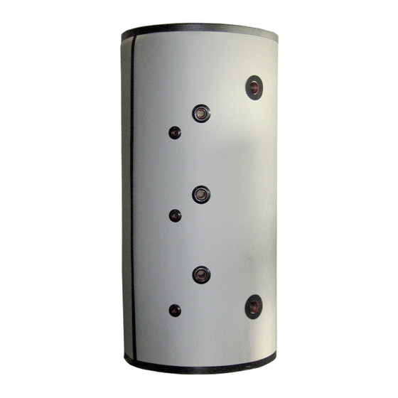
- Page 1 PSW 1000 Montageanweisung Installation instructions Instructions de montage Instrukcja montażu Pufferspeicher Buffer tank Ballon tampon Zasobnik 1000 Liter für (1000 litres) for de 1000 litres buforowy Wärmepumpen heat pumps pour les pompes 1000 litrowy dla à chaleur pomp ciepła Bestell-Nr. / Order no. / No de commande / Nr zamówienia: GDD/PSW 1000 FD 9901...
- Page 3 Inhaltsverzeichnis Aufstellung..........................DE-2 1.1 Sicherheitsventil:..........................DE-2 1.2 Inbetriebnahme:........................... DE-2 Technische Daten........................DE-3 2.1 Abmessungen Pufferspeicher PSW 1000 ................... DE-3 Technische Daten Pufferspeicher......................DE- www.dimplex.de DE-1...
- Page 4 Aufstellung 1.1 Sicherheitsventil: Wird der Pufferspeicher mit einem oder mehreren Tauchheizkör- Die Montage und Installation des Speichers muss durch eine zu- pern ausgerüstet muss dieser zusätzlich mit einem baumuster- gelassene Fachfirma erfolgen! geprüften, nicht absperrbaren Membran-Sicherheitsventil ausge- Der Pufferspeicher muss an einem frostsicheren Ort aufgestellt stattet werden.
- Page 5 Technische Daten 2.1 Abmessungen Pufferspeicher PSW 1000 Pos. 1: G 1 ½“i Pos. 2: G 1 ½“i Pos. 3: G ½“i Pos. 4: G 2 ½“i www.dimplex.de DE-3...
- Page 6 Zoll 1“ AG Solaranschluss Rücklauf Zoll 1“ AG Tauchhülsen Rp 1/2“, Länge 150mm Anzahl Stellfüße Anzahl zul. Betriebstemperatur Heizwasser °C zul. Betriebsdruck Heizwasser HINWEIS! Beigefügtes Typschild und Anschlussplan nach Aufstellung und Montage der Dämmung sichtbar auf den Speichermantel aufkleben. www.dimplex.de...
- Page 7 DE-5...
- Page 8 Table of contents Installation ..........................GB-2 1.1 Safety valve ............................GB-2 1.2 Start-up ..............................GB-2 Technical data ..........................GB-3 2.1 Buffer tank dimensions PSW 1000 ...................... GB-3 Technical Data Buffer tank ........................GB- www.dimplex.de GB-1...
- Page 9 Installation 1.1 Safety valve If the buffer tank is fitted with one or more immersion heaters, it The buffer tank must be mounted and installed by an authorised must additionally be equipped with a type-tested diaphragm specialist company! safety valve which cannot be shut off. The buffer tank must be installed in a frost-free location.
- Page 10 Technical data 2.1 Buffer tank dimensions PSW 1000 Pos. 1: G 1 ½“i Pos. 2: G 1 ½“i Pos. 3: G ½“i Pos. 4: G 2 ½“i www.dimplex.de GB-3...
- Page 11 Permissible operating temperature, heating water °C Permissible operating pressure, heating water NOTE After the tank has been installed and the insulation fitted, affix the supplied type plate and connection diagram so that they are visible on the buffer tank cladding. www.dimplex.de GB-4...
- Page 12 GB-5...
- Page 13 Table des matières Installation ..........................FR-2 1.1 Vanne de sécurité..........................FR-2 1.2 Mise en service.............................FR-2 Caractéristiques techniques ..................... FR-3 2.1 Dimensions du ballon tampon PSW 1000 ....................FR-3 Données techniques du ballon tampon ....................FR- www.dimplex.de FR-1...
- Page 14 Installation 1.1 Vanne de sécurité Si le ballon tampon est équipé d’une ou plusieurs résistances im- Le montage et l'installation du ballon doivent être effectués par mergées, celle(s)-ci doi(ven)t être pourvue(s) en plus d'une une entreprise spécialisée agréée ! vanne de sécurité à membrane homologuée, ne pouvant être Le ballon tampon doit être installé...
- Page 15 Caractéristiques techniques 2.1 Dimensions du ballon tampon PSW 1000 Pos. 1: G 1 ½“i Pos. 2: G 1 ½“i Pos. 3: G ½“i Pos. 4: G 2 ½“i www.dimplex.de FR-3...
- Page 16 Température de service admissible eau de chauffage °C Pression de service admissible eau de chauffage bars REMARQUE Apposer la plaque signalétique jointe et le schéma électrique de manière visible sur l'enveloppe du ballon une fois l'isolation montée et installée. www.dimplex.de FR-4...
- Page 17 FR-5...
- Page 18 Spis tresci Ustawienie........................... PL-2 1.1 Zawór bezpieczeństwa ......................... PL-2 1.2 Pierwsze uruchomienie......................... PL-2 Dane techniczne ......................... PL-3 2.1 Wymiary zasobnika buforowego PSW 1000..................PL-3 Dane techniczne zasobnika buforowego ....................PL- www.dimplex.de PL-1...
- Page 19 Ustawienie 1.1 Zawór bezpieczeństwa Jeżeli zasobnik buforowy jest wyposażony w jedną lub więcej Montaż instalację zasobnika musi przeprowadzić grzałek nurkowych, to musi posiadać dodatkowo sprawdzony specjalistyczna firma! pod względem typu konstrukcyjnego, niezamykający się Zasobnik buforowy należy ustawić w zabezpieczonym przed membranowy zawór bezpieczeństwa.
- Page 20 Dane techniczne 2.1 Wymiary zasobnika buforowego PSW 1000 Pos. 1: G 1 ½“i Pos. 2: G 1 ½“i Pos. 3: G ½“i Pos. 4: G 2 ½“i www.dimplex.de PL-3...
- Page 21 Rp 1/2“, Długość 150mm Ilość nóżki Ilość dopuszczalna temperatura robocza wody grzewczej °C dopuszczalne ciśnienie robocze wody grzewczej WSKAZÓWKA Po ustawieniu i montażu izolacji należy przykleić w widocznym miejscu na obudowie zasobnika załączoną tabliczkę znamionową i plan podłączeń. www.dimplex.de...
- Page 22 GDD GmbH Irrtümer und Änderungen vorbehalten. Subject to alterations and errors. Sous réserve d’erreurs et modifications. D-95326 Kulmbach Zastrzegamy sobie prawo do zmian oraz bledów.


