Publicité
Les langues disponibles
Les langues disponibles
Liens rapides
INSTALLATION INSTRUCTIONS
Note: Wires connecting between box(es) and from transformer must
be protected from abrasion, and being pulled at connections. They
also may have to be fished through at a later stage of construction.
Depending on installation, the cable bushings included may be
replaced by installer supplied 1/2" conduit. Rough-in box as per
Figure 1.
Note: Conduit can be permanently bent to hold shape.
The transformer is to be installed in an adjacent accessible space.
(Do NOT install the transformer inside the control box.) Cable
from the transformer to the driver board/controller may be roughed
in at this time depending on installation. Use cable which complies
to local electrical codes for a 1 amp load. No.18 is usually sufficient.
HARDWIRE OR BATTERY
: If recessed box is supplied, rough in
as per Figure 1. The most vandal resistant installation is when the
control box is as close to the bottom of the sink as feasible. For wall
hung sink installation, sensor conduit rough in should be directly
under the basin to minimize sensor cord exposure. Rough in
drainage. Rough in water supply to 10" control box inlets and to
spout connection. Finish walls.
Valve spacer is for temporary use only for flushing of system.
Must be replaced with solenoid (Fig. 2 & 3).
FLUSH SYSTEM/SET TEMPERATURE
Remove coverplate from control box. Open screwdriver stop(s) to
flush installation for 1 minute minimum.
A Run water for a sufficient time so the hot and cold water supplies
are as hot and cold as they will get.
B Thermostatic Mixing Valve (Fig. 3).
To adjust the mixed outlet temperature of the valve, remove
the cap to gain access to the adjusting spindle. The spindle
should be rotated towards the "C" side to reduce the temper-
ature and towards the "H" side to increase the temperature -
until the desired set point is reached (refer
to Fig. 4).
Periodic Inspection/Maintenance - We
recommend that this valve is checked at least
once per year to ensure its continued function.
For installations with poor or unknown water
quality, or other adverse supply conditions, it
may be necessary to check the valve at more
frequent intervals. The temperature should be
checked at the same outlet as was used for
commissioning in the first instance. If the
temperature is more than 3°F from the comm-
issioning in temperature, refer to the included
Maintenance and Installation Guide.
C Close stop(s).
(Do not over torque stop).
Fig. 4
Towards
"H" side to
increase
Towards
temperature
"C" side
to reduce
temperature
TMV Repair Kit
061137A - Adjustment Wrench
063164A - Check Valves (2/pkg)
Installation should be in accordance with local
plumbing and electrical codes.
FLUSH ALL PIPES THOROUGHLY BEFORE
INSTALLATION.
Remove suitable knockout(s) in box(es) and insert
cable bushing(s).
Fasten box to
framing using
holes provided
inside of box
257mm
(10.13")
Control Box
Rough-in box
to be installed
(flush to 1/4")
to finished wall
*
The rough 10" cover plate is intended for temporary use only and must be replaced
with permanent 12" plate after rough-in stage is complete.
The 12" permanent plate is included on the applicable "Trim" models.
If a "Trim" model was not ordered, repair parts 060577A (12" permanent plate) and
060073A (4 screws & driver bit) must be ordered separately.
Control Box #1
Flexible Sensor Cord
Conduit (supplied on
Recessed Mount Box)
063135A
Stop
w w w . s p e c s e l e c t . c o m
ELAVT0001ARI
ELAVT0008ARI
Finished
Wall
Flexible, Sensor
Cord Conduit
1/2" sweat connection
305mm (12")
Stainless Steel
Cover Plate
102mm (4")
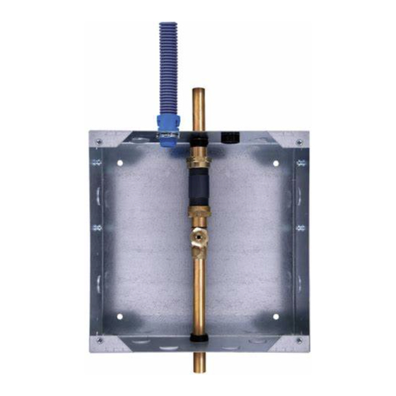
Fig. 2
Control Box #8
Hot Inlet
1/2" Sweat
1/2" Sweat
Outlet
Tempered Water
(By Others)
063135A
Stops
Inlet:
1/2" Sweat
Fig. 1
356mm
(14")
SUPPLIED:
max.
1/2" Sweat
Outlet from Box
BALANCE BY OTHERS
*
Product supplied as
shown by solid lines.
All items shown by
dotted lines supplied
by other or Trim
Package.
Flexible Sensor Cord
Conduit (supplied on
Recessed Mount Box)
Cold Inlet
1/2" Sweat
1/2" Sweat
Outlet
063179A
Thermostatic Mixing Valve
with checks and gaskets
210319 Rev. A
Fig. 3
Publicité

Manuels Connexes pour Delta ELAVT0001ARI


Sommaire des Matières pour Delta ELAVT0001ARI
- Page 1 ELAVT0001ARI Installation should be in accordance with local plumbing and electrical codes. FLUSH ALL PIPES THOROUGHLY BEFORE ELAVT0008ARI INSTALLATION. Remove suitable knockout(s) in box(es) and insert cable bushing(s). INSTALLATION INSTRUCTIONS Fig. 1 Note: Wires connecting between box(es) and from transformer must be protected from abrasion, and being pulled at connections.
- Page 2 ELAVT0001ARI L’installation doit être conforme aux Codes de plomberie et d’électricité locaux. VIDER SOIGNEUSEMENT TOUS LES TUYAUX ELAVT0008ARI AVANT DE PROCÉDER À L’INSTALLATION. Enlevez les entrées défonçables requises et insérer les bagues de cable. INSTRUCTIONS D’INSTALLATION Fig. 1 Remarque : Les câbles mis en circuit entre le ou les boîtiers et du trans- formateur doivent être protégés contre l’abrasion et tirés aux endroits où...