Publicité
Les langues disponibles
Les langues disponibles
Liens rapides
Publicité

Manuels Connexes pour Sovelor CYNOX50F


Sommaire des Matières pour Sovelor CYNOX50F
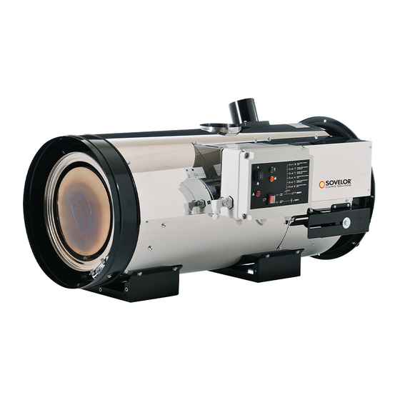
- Page 1 CYNOX50F - CYNOX100F...
- Page 2 ETICHETTA IDENTIFICAZIONE PRODOTTO – PLAQUETTE IDENTIFICATION PRODUIT TYPENSCHILD – PRODUCT IDENTIFICATION PLATE ETIQUETA DE IDENTIFICACIÓN DEL PRODUCTO – ПАСПОРТНАЯ ТАБЛИЧКА ИЗДЕЛИЯ COSTRUTTORE POTENZA TERMICA NOMINALE CONSTRUCTEUR PUISSANCE THERMIQUE NOMINALE HERSTELLER WÄRMELEISTUNG BEWERTET MANUFACTURER NOMINAL HEATING OUTPUT FABRICANTE POTENCIA TÉRMICA NOMINAL ИЗГОТОВИТЕЛЬ...
- Page 3 SCHÉMA DE FONCTIONNEMENT - OPERATING DIAGRAM SORTIE AIR CHAUD ENTREE AIR BRULEUR CHAMBRE DE COMBUSTION THERMOSTAT DE SECURITE A REARMEMENT MANUEL HOT AIR OUTFLOW BURNER AIR INFLOW COMBUSTION CHAMBER LIMIT THERMOSTAT WITH MANUAL RESTART, VENTILATEUR REFROIDISSEMENT CHEMINEE BRULEUR A FUEL CHIMNEY COOLING FAN DIESEL BURNER...
- Page 4 IMPORTANT Avant toute utilisation du générateur, nous vous prions de lire attentivement toutes les instructions pour l'emploi mentionnées ciaprès et d'en suivre scrupuleusement les indications. Le constructeur n'est pas responsable des dommages aux personnes et/ou aux biens dus à une utilisation impropre de l'appareil. Ce livret d'utilisation et d'entretien est partie intégrante de l'appareil.
- Page 5 ("TABLEAU DES CARACTÉRISTIQUES TECHNIQUES"); Attention S’assurer que les élingues et/ou les chaînes forment un • s’assurer que le débit d’air n’est pas inférieur au débit nominal ; vérifier l’absence d’obstacles ou d’obstructions à l’aspiration et/ou angle maximum de 5° avec la verticale au plafond, que les à...
- Page 6 CARACTERISTIQUES TECHNIQUES”. Attention Avant de mettre le générateur en marche, contrôler que le sens de rotation du ventilateur correspond bien à celui indiqué. 4.4. BRANCHEMENT À LIGNE D'ALIMENTATION COMBUSTIBLE Attention Les prescriptions d'installation, de réglage et d'utilisation visées par les réglementations régionales et/ou nationales concernant l'emploi du générateur d'air chaud doivent impérativement toujours être respectées.
- Page 7 5. INSTRUCTIONS D'UTILISATION électrique d'alimentation. • Attendre que le générateur soit froid. 5.1. MISE EN MARCHE Pour mettre le générateur en marche : • S'assurer que le commutateur (a) est sur la position “0” ; • Alimenter l'appareil en agissant sur l'interrupteur général de Entretien périodique l’armoire électrique d'alimentation : le témoin rouge (b) s’allume Intervention...
- Page 8 6.3 Nettoyage du moteur et du ventilateur s'assurer : • que le câble d'alimentation électrique a été débranché et retiré de Pour nettoyer le aubes du ventilateur et le moteur, procéder comme suit : la prise d'alimentation • Retirer les deux vis (A) latérales de fixation du groupe ventilateur, •...
- Page 9 7. ANOMALIES DE FONCTIONNEMENT, CAUSES ET SOLUTIONS En cas de grave anomalie, l’équipement électronique entraînera le blocage de sécurité du générateur d’air chaud et le témoin (d) s’allumera en rouge fixe Attention Après un blocage de sécurité, il est nécessaire d'appuyer sur le bouton réarmement (d) pendant 3 secondes pour faire redémarrer le générateur.
- Page 10 ANOMALIE DE FONCTIONNEMENT CAUSE SOLUTION • Enroulement du moteur de brûleur endommagé • Remplacer le moteur • Coussinets du moteur de brûleur bloqués • Remplacer les coussinets • Condensateur du moteur de brûleur grillé • Remplacer le condensateur • Vérifier les branchements des câbles • d’allumage aux électrodes et au transformateur •...
- Page 11 IMPORTANT Before using the space heater, carefully read all of the instructions and follow them scrupulously. The manufacturer cannot be held responsible for damage to persons and/or property caused by improper use of the equipment. This instruction manual is an integral part of the equipment and must therefore be stored carefully and passed on with the unit in the event of a change of ownership.
- Page 12 4.1. INSTALLATION ON FLOOR OR CEILING Warning The temporary power cable must be removed and replaced The space heater can be installed on a support base, which must be: • stable and horizontal with a H07RN-F cable having a section of at least 1.5 •...
- Page 13 4.6. CONNECTION TO EXHAUST DUCT Exhaust ducts must be in steel and conform to EN 1443. Efficient combustion and trouble-free working of the burner depend on efficient flue draft. The unit must be connected to the chimney flue in compliance with current legal regulations and in line with the following guidelines: •...
- Page 14 Warning 6.3 Cleaning the motor and the fan Before doing any maintenance: Clean the fan blades and the motor as follows: • Stop the heater as indicated in the “STOP” paragraph; • Remove the two side fixing screws (A) on the fan group, slide the •...
- Page 15 6.8 CLEANING THE COMBUSTION CHAMBER To maintain the burner’s high efficiency and prolong its life, the procedure described in this paragraph must be done at least once at the end of the work season or more frequently if there is an excessive build-up of soot.
- Page 16 7. TROUBLESHOOTING In case of serious malfunction, the electronic equipment causes the heater to go into safety stop, and lamp (d) lights with a steady red light Warning In case of a safety stop, you have to push the reset button (d) for 3 seconds to restart the heater.
- Page 17 FAULT CAUSE REMEDY • Burner motor winding is damaged • Replace motor • Burner motor bearing blocked • Replace bearings • Burner motor condenser burned out • Replace condenser • Check connections of ignition wires to electrodes and transformer • Defective ignition •...
- Page 18 SCHEMA ELECTRIQUE – WIRING DIAGRAM L-L 196.00-BM 48 / 52...
- Page 19 SCHEMA ELECTRIQUE – WIRING DIAGRAM CONDENSATEUR VOYANT PRÉSENCE FLAMME FLAME DETECTION LIGHT CONDENSER MOTEUR VENTILATEUR THERMOSTAT BRULEUR FAN MOTOR BURNER THERMOSTAT THERMOSTAT VENTILATEUR PRISE THERMOSTAT D’AMBIACE FAN THERMOSTAT ROOM THERMOSTAT PLUG FUSIBLE BOUTON REARMEMENT FUSE RESET BUTTON LAMPE TEMOIN MISE SOUS TENSION TÉMOIN BLOCAGE CONTROL LAMP LOCK OUT INDICATOR LIGHT...
- Page 20 CARACTERISTIQUES TECHNIQUES TECHNICAL SPECIFICATIONS CYNOX 50 F Protection IP - IP protection IP X4D Type – B Bruleur - Burner RIELLO RDB2 Combustible fuel Puissance thermique max mesuré [kcal/h] 42869 Max measured heating output [kW] 49,8 [BTU/h] 170619 Puissance thermique nette mesuré [kcal/h] 38153 Net measured heating output...
- Page 21 CARATTERISTICHE TECNICHE - CARACTERISTIQUES TECHNIQUES TECHNISCHEN DATEN - TECHNICAL SPECIFICATIONS CYNOX 100 F CARACTERÍSTICAS TÉCNICAS - ТЕХНИЧЕСКИЕ ХАРАКТЕРИСТИКИ Protection IP - IP protection IP X4D Type - Type – B Bruleur - Burner RIELLO RDB4 Combustible FUEL [kcal/h] 85869 Puissance thermique max mesuré [kW] 99,8 Max measured heating output...
- Page 22 CYNOX50F L-D359.00-BM 57 56 Optional 20 21...
- Page 23 CYNOX50F L-D359.00-BM Da N.° serie Von Masch. Nr. From S/N PL 08/14 De No. Serie 56900001 LEGENDA DESCRIZIONE DESCRIPTION BESCHREIBUNG DESCRIPTION G03332-X Carrozzeria superiore Carrosserie sup. Karosserie Oberteil Upper body G03316-9005 Presa aria bruciatore Entrée d'air Lufteinlass Brenner Air intake...
- Page 24 CYNOX50F L-D359.00-BM Da N.° serie Von Masch. Nr. From S/N PL 08/14 De No. Serie 56900001 LEGENDA DESCRIZIONE DESCRIPTION BESCHREIBUNG DESCRIPTION E20305 Morsettiera Barrette de connection Klemmenleiste Terminal board 12 pin E20319 Morsettiera per cavi terra Barrette de connection Klemmenleiste für Erdungskabel...
- Page 25 CYNOX100F L-D361.00-BM 57 56 Optional 11 12 20 21...
- Page 26 CYNOX100F L-D361.00-BM Da N.° serie Von Masch. Nr. From S/N PL 08/14 De No. Serie 57100001 LEGENDA DESCRIZIONE DESCRIPTION BESCHREIBUNG DESCRIPTION G03350-X Carrozzeria superiore Carrosserie sup. Karosserie Oberteil Upper body G03316-9005 Presa aria bruciatore Entrée d'air Lufteinlass Brenner Air intake G03338-X Pannello ispezione Porte visite...
- Page 27 CYNOX100F L-D361.00-BM Da N.° serie Von Masch. Nr. From S/N PL 08/14 De No. Serie 57100001 LEGENDA DESCRIZIONE DESCRIPTION BESCHREIBUNG DESCRIPTION E20305 Morsettiera Barrette de connection Klemmenleiste Terminal board 12 pin E20319 Morsettiera per cavi terra Barrette de connection Klemmenleiste für Erdungskabel Ground terminal board E20955 Dado per pressacavo...
- Page 28 Dantherm S.p.A. Dantherm S.p.A. Via Gardesana 11, -37010- 11, 37010 Pastrengo (VR), ITALY Dantherm Sp. z o.o. Dantherm Sp. z o.o. ul. Magazynowa 5A, 62-023 Dantherm SAS Dantherm SAS Dantherm LLC ul. Transportnaya 22/2, Dantherm China LTD Dantherm China LTD Dantherm SP S.A.