Table des Matières
Publicité
Les langues disponibles
Les langues disponibles
Liens rapides
To learn more about DELTA MACHINERY
visit our website at: www.deltamachinery.com.
For Parts, Service, Warranty or other Assistance,
1-800-223-7278 (
please call
10" Motorized
Bench Saw
1-800-463-3582).
In Canada call
(SM200L)
PART NO. 491720-00 10-30-05
Copyright © 2005 Delta Machinery
ESPAÑOL: PÁGINA 27
FRANÇAIS: PAGE 51
Publicité
Table des Matières

Manuels Connexes pour Delta ShopMaster SM200L


Sommaire des Matières pour Delta ShopMaster SM200L
- Page 1 10" Motorized Bench Saw (SM200L) PART NO. 491720-00 10-30-05 Copyright © 2005 Delta Machinery To learn more about DELTA MACHINERY ESPAÑOL: PÁGINA 27 visit our website at: www.deltamachinery.com. FRANÇAIS: PAGE 51 For Parts, Service, Warranty or other Assistance, 1-800-223-7278 ( 1-800-463-3582).
-
Page 2: Table Des Matières
NOT be modified and/or used for any application other than for which it was designed. If you have any questions relative to its application DO NOT use the product until you have written Delta Machinery and we have advised you. - Page 3 SAFETY GUIDELINES - DEFINITIONS It is important for you to read and understand this manual. The information it contains relates to protecting YOUR SAFETY and PREVENTING PROBLEMS. The symbols below are used to help you recognize this information. Indicates an imminently hazardous situation which, if not avoided, will result in death or serious injury. Indicates a potentially hazardous situation which, if not avoided, could result in death or serious injury.
-
Page 4: Important Safety Instructions
13. USE RECOMMENDED ACCESSORIES. The use of appropriate for the dust exposure, and wash exposed accessories and attachments not recommended by areas with soap and water. Delta may cause damage to the machine or injury to the... -
Page 5: Additional Specific Safety Rules
ADDITIONAL SPECIFIC SAFETY RULES READ AND UNDERSTAND ALL INSTRUCTIONS. FAILURE TO FOLLOW THESE INSTRUCTIONS MAY RESULT IN ELECTRICAL SHOCK, FIRE AND / OR SERIOUS INJURY. DO NOT OPERATE THIS MACHINE until it is 10. CUTTING THE WORKPIECE WITHOUT THE USE OF assembled and installed according to the instructions. - Page 6 POWER CONNECTIONS A separate electrical circuit should be used for your machines. This circuit should not be less than #12 wire and should be protected with a 20 Amp time lag fuse. If an extension cord is used, use only 3-wire extension cords which have 3- prong grounding type plugs and matching receptacle which will accept the machine’s plug.
-
Page 7: Functional Description
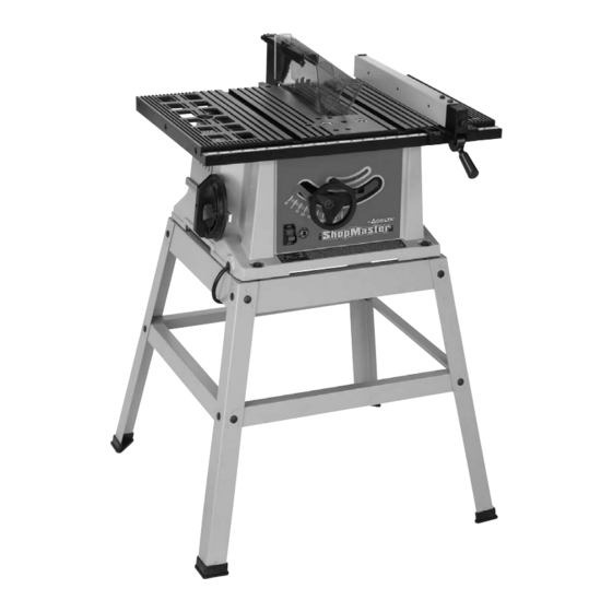
ShopMaster Model SM200L is a 10" Table Saw designed to give high quality performance with depth of cut capacity up to 3" (76mm) at 90° and 2" (51mm) at 45° for clean cutting of standard stock sizes. Delta ShopMaster Model TS200LS includes the saw with a 13 amp 120V motor, a metal stand, rip fence, miter gage, see-through blade guard with splitter and anti-kickback fingers, a 10”... - Page 8 Fig. 2 Fig. 2 Parts Fig. 3 1. Rip Fence Fig. 3 Hardware 2. Splitter and Guard Assembly 3. Lock Handle for Rip Fence 1. M6x1x55mm Pan Head Screw (1) 4. Blade Raising and Lowering Handwheel 2. 1/4-20x2fi" Hex Head Screw (1) 5.
-
Page 9: Assembly
UNPACKING AND CLEANING Carefully unpack the machine and all loose items from the shipping container(s). Remove the protective coating from all unpainted surfaces. This coating may be removed with a soft cloth moistened with kerosene (do not use acetone, gasoline or lacquer thinner for this purpose). - Page 10 ASSEMBLING STAND 1. Assemble the stand as shown in Fig. 4C, using 16 M8x1.25x20mm carriage head bolts, 3/8" flat washers and M8x1.25 hex nuts. Align the holes in the stand legs (F) with the holes in the brackets. Insert the carriage head bolt through the hole in the leg and the hole in the bracket, place a flat washer on the carriage head bolt and thread a hex nut onto the carriage head bolt.
- Page 11 ATTACHING BLADE HEIGHT ADJUSTING HANDWHEEL 1. Insert an M6x1x55mm pan head screw (D) Fig. 5 through the handle (E). Attach the handle (E) to the handwheel (A) by threading the screw (D) clockwise into the handwheel. 2. Attach the handwheel (A) Fig. 6 to the shaft (B). Align the flat on the inside of the handwheel to the flat on the shaft. Fig.
- Page 12 Locate the 1/4-20x2fi" hex head screw (G) Fig. 10. Place the 1/4" internal tooth lockwasher (O) M6.4 flat washer (P) and the 1/4" external tooth lockwasher (R) on the screw (G). Position the recessed end (E) Fig. 11 of the splitter bracket (B) against the end of the pivot rod (F), and fasten using the assembly in STEP 3.
- Page 13 NOTE: Before tightening the wing nut (M) Fig. 15, make certain a gap of at least 1/8" is between the bottom edge of the splitter (N) and the top surface of the table (P) and that the protrusions (K) are inside the slot of the splitter assembly (H).
- Page 14 Attach the spring clip (E) Fig. 19 to the miter gauge holder (A) using an M4x.7x10mm pan head screw (F), 3/16" external tooth lockwasher, (B) and M4x.7 hex nut. NOTE: The hex nut (G) Fig. 20 will fit into the recess at the back of the miter gauge holder (A) Fig. 19 to keep the spring clip (E) secured to the miter gauge holder.
-
Page 15: Operation
OPERATION OPERATIONAL CONTROLS AND ADJUSTMENTS STARTING AND STOPPING SAW The on/off switch (A) Fig. 27 is located on the front of the saw cabinet. To turn the saw “ON”, move the switch (A) up to the “ON” position. To turn the saw “OFF”, move the switch (A) down to the “OFF” position. MAKE SURE THAT THE SWITCH IS IN THE “OFF”... - Page 16 BLADE TILT ADJUSTMENT To tilt the saw blade, loosen the lock handle (A) Fig. 30 and move the handwheel (B) until the blade is at the desired angle. Tighten the lock handle (A). NOTE: The lock handle (A) is spring-loaded. Pull out on the handle (A) and reposition it on the serrated stud located underneath the handle.
- Page 17 RIP FENCE OPERATION AND ADJUSTMENTS 1. To move the rip fence (A) Fig. 33 along the table, lift up the fence locking lever (B), slide the fence to the desired location on the table, and push down the fence locking lever (B). 2.
- Page 18 MITER GAUGE OPERATION AND ADJUSTMENTS For cross-cutting (blade set 90 degrees to the table), the miter gauge can be used in either table slot. For bevel cross-cutting (with the blade tilted), use the miter gauge in the right table slot only so that the blade will be tilted away from the miter gauge and your hands.
- Page 19 The following information describes the safe and proper method for performing the most common sawing operations. THE USE OF ATTACHMENTS AND ACCESSORIES NOT RECOMMENDED BY DELTA MAY RESULT IN THE RISK OF INJURY TO THE USER OR OTHERS.
- Page 20 THE SAW BLADE GUARD MUST BE USED. ON DELTA SAWS, THE GUARD HAS ANTI-KICKBACK FINGERS TO PREVENT KICKBACK AND A SPLITTER TO PREVENT THE WOOD KERF FROM CLOSING AND BINDING THE BLADE.
- Page 21 feet, use a work support at the rear of the saw to keep the workpiece from falling off the saw table. 3. If the ripped work is less than 6 inches wide, a push stick should always be used to complete the feed, as shown in Fig.
- Page 22 1. Dadoing is cutting a rabbet or wide groove into the work. Most dado head sets are made up of two outside saws and four or five inside cutters, (Fig. 44A). Various combinations of saws and cutters are used to cut grooves from 1/8”...
- Page 23 CONSTRUCTING A PUSH STICK When ripping work less than 4 inches wide, a push stick should be used to complete the feed and could be easily made from scrap material by following the pattern shown in Fig. 48B.
- Page 24 Kerf should be about 1/4" apart. Fig. 49 Further information on the safe and proper operation of table saws is available in the Delta “Getting the Most Out of Your Table Saw” How- To Book, Catalog No. 11-400. Additional Information on table saw safety, including a...
-
Page 25: Troubleshooting
1.Stand or bench on uneven floor. 1.Reposition on flat level surface. 2.Damaged saw blade. 2.Replace blade. For assistance with your machine, visit our website at www.deltamachinery.com for a list of service centers or call the DELTA Machinery help line at 1-800-223-7278 (In Canada call 1-800-463-3582). -
Page 26: Maintenance
Two Year Limited New Product Warranty Delta will repair or replace, at its expense and at its option, any new Delta machine, machine part, or machine accessory which in normal use has proven to be defective in workmanship or material, provided that the customer returns the product prepaid to a Delta factory service center or authorized service station with proof of purchase of the product within two years and provides Delta with reasonable opportunity to verify the alleged defect by inspection. - Page 27 Sierra Motorizada de Banco de 10 pulg. (Modelo SM200L) 491720-00 10-30-05 Copyright © 2005 Delta Machinery Para obtener más información sobre Delta Machinery, visite nuestro sitio web en: www.deltamachinery.com Para las piezas, el servicio, la garantía o la otra ayuda 1-800-223-7278 ( 1-800-463-3582...
- Page 28 Si usted tiene cualquiera pregunta el pariente a su aplicación no utiliza el producto hasta que usted haya escrito Delta Machinery y nosotros lo hemos aconsejado.
- Page 29 UTILICE ACCESORIOS RECOMENDADOS. La utilización NIOSH/OSHA que se ajuste apropiadamente y sea de accesorios y aditamentos no recomendados por Delta adecuada para la exposición al polvo, y lávese las áreas podría causar daños a la máquina o lesiones al usuario.
- Page 30 REGLAS DE SEGURIDAD ADICIONALES PARA SIERRA DE MESA ES IMPORTANTE PARA USTED LEER Y ENTENDER ESTE MANUAL. EL INCUMPLIMIENTO DE LAS INSTRUCCIONES ENUMERADAS DEBAJO PUEDE PROVOCAR DESCARGA ELÉCTRICA, INCENDIO O LESIONES GRAVES. UTILICE ESTA MÁQUINA hasta esté NUNCA haga pasar la pieza de trabajo entre el tope-guía completamente montada e instalada de acuerdo con las y una fresa de moldurar.
- Page 31 CONEXIONES A LA FUENTE DE ALIMENTACIÓN Debe utilizarse un circuito eléctrico independiente para las máquinas. Este circuito debe tener alambre de no menos del No. 12 y debe estar protegido con un fusible de acción retardada de 20 A. Si se utiliza un cordón de extensión, utilice únicamente cordones de extensión de tres alambres que tengan enchufes de tipo de conexión a tierra con tres terminales y un receptáculo coincidente que acepte el enchufe de la máquina.
- Page 32 INSTRUCCIONES DE FUNCIONAMIENTO La ShopMaster modelo SM200L de Delta es una sierra de mesa de 10" diseñada para brindar un rendimiento de alta calidad, con una capacidad de profundidad de corte de hasta 3" (76 mm) a 90° y 2" (51 mm) a 45°, para cortar limpiamente tamaños de material estándar.
- Page 33 Fig. 2 Fig. 2 Fig. 3 1. Guía de corte a lo largo Fig. 3 2. Ensamblaje de hendidor y protector 1. M6x1x55mm Tornillo de la pista de la cacerola de (1) 3. Agarradera de cierre para la guía de corte a lo largo 2.
- Page 34 DESEMPAQUETADO Y LIMPIEZA Desempaque cuidadosamente la máquina y todas las piezas sueltas que están en el contenedor o contenedores de transporte. Quite el revestimiento protector de todas las superficies no pintadas. Este revestimiento puede quitarse con un paño suave humedecido con queroseno (no utilice acetona, gasolina ni diluyente de laca para este fin). Después de realizar la limpieza, cubra las superficies no pintadas con una cera en pasta doméstica de buena calidad para pisos.
- Page 35 MONTAJE DE LA BASE DE SOPORTE SM200L 1. Monte la base de soporte de la manera que se muestra en la Fig. 4C, utilizando 16 pernos de M8x1.25x20mm carruaje, 3/8 plug. arandelas planas y M8x1.25 tuercas hexagonales. No apriete completamente los herrajes en este momento. Hay letras estampadas en las ménsulas de la base de soporte para facilitar el montaje.
- Page 36 2. Ensamble el volante de mano (A) Fig. 6 al eje (B), asegurando que el plano en el lado interior del volante de mano se alinee con el plano del eje. 3. Fije el volante de mano (A) Fig. 7 al eje, utilizando el tornillo M6x1x12mm screw (C). Fig.
- Page 37 Fig. 13 Fig. 14 Fig. 15 Fig. 16 Afiance el hendidor (L) Fig. 14 al soporte de apoyo del hendidor utilizando una arandela plana, una arandela de cierre de dientes externos, y una M6 tuerca de mariposa (M). AVISO: Antes de apretar la tuerca de mariposa (M), asegúrese de que haya una abertura de por lo menos 1/8 pulg.
- Page 38 ENSAMBLADO DEL PORTADOR DE LA ESCUADRA DE INGLETES DESCONCTE LA MAQUINA DE LA FUENTE DE ALIMENTACION. 1. Ensamble fig. 19 del (E) del clip de resorte, el (A) del sostenedor de la galga de los ingletes según lo mostrado usando un tornillo de la pista de la cacerola de M4x.7x10mm (F), el (B) de la arandela de cierre del diente del 3/16" y la tuerca de tuerca hexagonal externos M4x.7.
- Page 39 Fig. 24 Fig. 25 ENSAMBLADO DE LA GUIA DE CORTE A LO LARGO Enrosque la M8x1.25 tuerca de cierre (A) Fig. 24 aproximadamente a la mitad del camino sobre el gorrón de la agarradera (B). Enrosque la tuerca de cierre (B) Fig. 24 dentro del agujero roscado (C) en la leva de la guía (D).
- Page 40 FIJANDO EL INTERRUPTOR EN LA POSICION DE APAGADO Sugerimos que cuando la sierra no se encuentre en uso que el interruptor quede fijado en la posición de apagado. Esto puede hacerse tomando la pieza acodada (B) y removiéndolo por completo del interruptor, tal como se ilustra en la Fig.
- Page 41 AJUSTANDO LOS TOPES POSITIVOS DE 90 Y 45 GRADOS Su sierra está equipada con topes positivos que colocarán rápida y precisamente la hoja de la sierra a 90 y a 45 grados a la mesa. DESCONCTE LA MAQUINA DE LA FUENTE DE ALIMENTACION. PARA AJUSTAR EL TOPE POSITIVO A LOS 90 GRADOS Eleve la hoja de la sierra a su elevación máxima.
- Page 42 La hoja de la sierra está colocada de forma paralela a la ranura de la escuadra de ingletes en la fábrica, y la guía debe estar paralela a la ranura de la escuadra de ingletes para realizar una labor acertada e impedir los contragolpes durante el corte a lo largo.
- Page 43 La información que aparece a continuación describe el método seguro y adecuado de realizar las operaciones de aserrado más comunes. EL USO DE ADITAMENTOS Y ACCESORIOS NO RECOMENDADOS POR DELTA PUEDE CAUSAR RIESGO DE LESIONES PARA EL USUARIO Y OTRAS PERSONAS.
- Page 44 REALIZACIÓN DE CORTES TRANSVERSALES La realización de cortes transversales requiere el uso del calibre de ingletes para posicionar y guiar la pieza de trabajo. Coloque la pieza de trabajo contra el calibre de ingletes y haga avanzar tanto dicho calibre como la pieza de trabajo hacia la hoja de sierra, de la manera que se muestra en la Fig.
- Page 45 SE DEBE USAR EL PROTECTOR DE LA HOJA DE SIERRA. EN LAS SIERRAS PORTER-CABLE, PROTECTOR TIENE DEDOS ANTIRRETROCESO PARA EVITAR EL RETROCESO Y UN SEPARADOR PARA EVITAR QUE LA SEPARACIÓN DE CORTE DE LA MADERA SE CIERRE Y ATORE LA HOJA. ESTÉ SEGURO REEMPLAZAR O AFILAR LOS ANTIRRETROCESO CUANDO LOS PUNTOS LLEGAN A SER LÁNGUIDOS.
- Page 46 UTILIZACIÓN DE UN REFRENTADO DE MADERA AUXILIAR EN EL TOPE-GUÍA PARA CORTAR AL HILO En algunas operaciones especiales se necesitan refrentados de madera (A), Fig. 43A, a un lado o a ambos lados del tope-guía para cortar al hilo. El refrentado de madera se sujeta al tope-guía con tornillos a través de los agujeros del tope-guía.
- Page 47 2. Coloque el juego de fresa de ranurar (D), Fig. 47, en el eje portaherramienta de la sierra. NOTE: LA PESTAÑA EXTERIOR DEL EJE PORTAHERRAMIENTA NO SE PUEDE UTILIZAR CON EL JUEGO DE FRESA DE RANURAR. APRIETE LA TUERCA DEL EJE PORTAHERRAMIENTA CONTRA EL CUERPO DEL JUEGO DE FRESA DE RANURAR.
- Page 48 2.Remplacer la lame. Para obtener asistencia para su máquina, visite nuestro sitio Web en www.deltamachinery.com para tener acceso a una lista de centros de servicio o llame a la línea de ayuda de Delta Machinery al 1-800-223-7278. (En Canadá, llame al 1-800-463-3582.)
- Page 49 CONSTRUCCIÓN DE UN PALO DE EMPUJAR Cuando vaya a cortar a lo largo materiales de menos de 100 mm (4 pulg.) de ancho, deber a utilizarse una vara de empuje para completar la alimentación. La vara puede hacerse fácilmente de material descartado, siguiendo el patrón ilustrado en la Fig.
- Page 50 Delta o autorizado por Delta dentro de dos años y proporcione a Delta una oportunidad suficiente como para verificar el alegado defecto por inspección.
- Page 51 10 po (25,4 cm) (SM200L) 491720-00 10-30-05 Copyright © 2005 Delta Machinery Pour en savoir plus à propos de DELTA MACHINERY consulter le site Web au : www.deltamachinery.com. Pour des pièces, réparations, garantie ou toute autre demande d’aide 1-800-223-7278 1-800-463-3582).
- Page 52 Delta Machinery recommande fortement de NE PAS modifier ce produit ou de NE PAS l’utiliser pour une application autre que celle pour laquelle il a été conçu. Si vous avez des questions à propos de son utilisation, N’utilisez PAS le produit avant de communiquer avec Delta Machinery et d’obtenir nos conseils.
- Page 53 LIGNES DIRECTRICES EN MATIÈRE DE SÉCURITÉ — DÉFINITIONS Il est important que vous lisiez et compreniez ce mode d’emploi. Les informations qu’il contient concernent VOTRE SÉCURITÉ et visent à ÉVITER TOUT PROBLÈME. Les symboles ci-dessous servent à vous aider à reconnaître cette information.
- Page 54 DIRECTIVES DE SÉCURITÉ IMPORTANTES POUR SA PROPRE SÉCURITÉ, LIRE LE MODE L'utilisation d'accessoires non recommandés par Delta D’EMPLOI AVANT D’UTILISER L’OUTIL. L’apprentissage pourrait endommager l'appareil ou blesser l'utilisateur. de l’utilisation de cet outil, des restrictions, et des risques 14.
- Page 55 RÈGLES DE SÉCURITÉ SPÉCIFIQUES SUPPLÉMENTAIRES LIRE ATTENTIVEMENT TOUTES LES MISES EN GARDE ET DIRECTIVES D’UTILISATION AVERTISSEMENT AVANT D’UTILISER CET ÉQUIPEMENT. À défaut de suivre les directives sous mentionnées, un choc électrique, un incendie, des dommages ou une blessure corporelle grave pourraient survenir.
- Page 56 CONNEXIONS ÉLECTRIQUES Un circuit électrique séparé doit être utilisé pour vos machines. Ce circuit doit utiliser un câble de calibre 12 au minimum et doit être protégé par un fusible temporisé de 20 A. Si vous utilisez une rallonge électrique, n’utiliser que des rallonges à...
- Page 57 RALLONGES ÉLECTRIQUES RALLONGE DE CALIBRE MINIMUM CALIBRES RECOMMANDÉS POUR UNE UTILISATION AVEC DES MACHINES AVERTISSEMENT Utiliser rallonges appropriées ÉLECTRIQUES D’ÉTABLI S'assurer que la rallonge est en bon état et qu’il s’agit Intensité Longueur totale Calibre de d’une rallonge à 3 fils avec une fiche de mise à la terre à...
- Page 58 Fig. 2 Fig. 3 Figure 2 Pièces Figure 3 Visserie 1. Guide longitudinal 2. Assemble couteau séparateur/pare-main 1. (1) Vis à tête cylindrique à dépouille M6x1x55 mm 3. Poignée de blocage pour le guide longitudinal 2. (1) Vis à tête hexagonale de 1/4-20x2 po 4.
- Page 59 DÉSEMBALLAGE ET NETTOYAGE Désemballer soigneusement la machine et toutes les pièces de ou des emballage(s) d'expédition. Retirer le revêtement protecteur de toutes les surfaces non peintes Le revêtement peut être retiré avec un chiffon doux humidifié avec du kérosène (ne pas utiliser d'acétone, d'essence ou de diluant à laque). Après le nettoyage, couvrir les surfaces non peintes d’une cire à...
- Page 60 ASSEMBLAGE DU SOCLE 1. Assembler le socle comme indiqué à la figure 4C avec les 16 boulons de carrosserie de M8x1, 25x20 mm, les rondelles plates de 3/8 po (9,5 mm) et les écrous hexagonaux de M8x1,25. Aligner les trous des pattes du socle (F) avec les trous des supports.
- Page 61 FIXATION DU VOLANT SERVANT À RÉGLER LA HAUTEUR DE LA LAME 1. Insérer une vis à tête cylindrique à dépouille de M6x de 1 x 55 mm (D, fig. 5) à travers la poignée (E). Fixer la poignée (E) au volant (A) en enfilant la vis (D) en sens horaire sur le volant. 2.
- Page 62 Localiser la vis à tête hexagonale 1/4-20x2 po (G, fig. 10. Placer la rondelle à denture intérieure de 1/4 po (6,4 mm) (O), la rondelle plate M6.4 (P) et la rondelle à denture extérieure de 1/4 po (6,4 mm) (R) sur la vis (G). Positionner l’extrémité...
- Page 63 REMARQUE : avant de resserrer l'écrou (M) fig. 15, s'assurer d'avoir un jeu d'au moins 3,1 mm (1/8 po) entre le bord inférieur du couteau séparateur (N) et la surface supérieur de la table (P) et que les saillies (K) soient à...
- Page 64 Fixer l'attache à ressort (E) fig. 19 du porte-jauge à onglet (A) en utilisant une vis à tête cylindrique de M4x de 0,7 x 10 mm (F), une rondelle à denture extérieure de 3/16 po (4,8 mm), (B) et un écrou hexagonal M4x de 0,7. REMARQUE : l'écrou hexagonal (G) fig.
- Page 65 FONCTIONNEMENT COMMANDES ET RÉGLAGES OPÉRATIONNELS DÉMARRAGE ET ARRÊT DE LA SCIE L'interrupteur marche/arrêt (A) fig. 27 se trouve à l'avant de l'armoire de la scie. Pour mettre la scie en marche, déplacer l'interrupteur (A) vers le haut à la position « MARCHE » (ON). Pour mettre la scie en marche, déplacer l'interrupteur (A) vers le haut à...
- Page 66 RÉGLAGE DE L’INCLINAISON DE LA LAME Pour incliner la lame de la scie, desserrer la poignée de verrouillage (A) fig. 30, et déplacer le volant (B) jusqu'à ce que la lame soit à l'angle voulu.Serrer la poignée de verrouillage (A). REMARQUE : La poignée de verrouillage (A) est à...
- Page 67 UTILISATION ET RÉGLAGES DU GUIDE LONGITUDINAL 1. Pour déplacer le guide longitudinal (A) fig. 33 le long de la table, soulever le levier de verrouillage du guide, le glisser jusqu'à l'emplacement voulu sur la table puis pousser vers le bas sur le levier de verrouillage du guide (B).
- Page 68 UTILISATION ET RÉGLAGES DE LA JAUGE À ONGLET Pour le tronçonnage (lame à 90 degrés de la table la jauge à onglet peut être utilisée dans l'une ou l'autre fente sur la table. Pour un tronçonnage en biseau (avec la lame inclinée) utiliser la jauge à...
- Page 69 être blessé. L'information suivante décrit la méthode appropriée et sans danger d'exécuter les opérations les plus courantes de sciage. AVERTISSEMENT L'UTILISATION D'ACCESSOIRES NON RECOMMANDÉS PAR DELTA POURRAIT PROVOQUER DES RISQUES DE BLESSURES POUR L'UTILISATEUR OU POUR D'AUTRES. TRONÇONNAGE Le tronçonnage nécessite l’utilisation de la jauge à...
- Page 70 Fig. 39B AVERTISSEMENT LE PARE-MAIN DE LA LAME DE SCIE DOIT ÊTRE UTILISÉ SUR LES SCIES DELTA, LE DISPOSITIF COMPORTE DES DOIGTS ANTI-EFFET DE REBOND POUR PRÉVENIR L'EFFET DE REBOND ET UN COUTEAU SÉPRATEUR POUR EMPÊCHER LE TRAIT DE BOIS DE SE FERMER ET DE COINCER LA LAME.
- Page 71 doit pas être touchée jusqu’à ce que la lame s'immobilise, à moins qu’il ne s’agisse d’une grande pièce pouvant être retirée en toute sécurité. Pour scier en long des planches de plus de trois pieds (914 mm) de long, utiliser un support de pièce à l’arrière de la scie afin d’empêcher la pièce de tomber hors de la table.
- Page 72 1. Le rainurage consiste à couper une feuillure ou une rainure large dans une pièce. La plupart des ensembles à rainurer sont constitués de deux scies externes et de quatre ou cinq couteaux internes (figure 44A). Diverses combinaisons de lames et de couteaux sont utilisées pour couper les rainures de 1/8 po à...
- Page 73 « FABRICATION D'UN POUSSOIR » Pour scier en long une pièce de moins de 15,24 cm (4 po) de largeur, utiliser un poussoir pour terminer la coupe. Il est facile de fabriquer un poussoir avec des déchets de découpe en suivant le patron indiqué à la figure 48B.
- Page 74 D'autre information au sujet de l'utilisation sans danger et appropriée des scies de table se trouve dans le guide pratique disponible auprès de Delta “Getting the Most Out of Your Table Saw”, no. de catalogue : 11-400. Vous pouvez obtenir d'autre information sur la sécurité...
- Page 75 2.Lame de scie endommagée. 2.Remplacer la lame. Pour obtenir de l’aide au sujet de l’outil, consulter notre site Web www.deltamachinery.com pour obtenir une liste des centres de réparation ou composer le 1-800-223-7278 du Centre de dépannage DELTA Machinery (au Canada, composer le 1-800-463-3582).
- Page 76 à condition que le client retourne le produit (transport payé d'avance) au centre de réparation de l'usine Delta ou à un centre de réparation autorisé accompagné d'une preuve d'achat et dans les deux ans de la date d'achat du produit, et fournisse à...
- Page 77 Fax: (519) 767-4131 Phone: (514) 336-8772 Fax: (514) 336-3505 The following are trademarks of PORTER-CABLE • DELTA (Las siguientes son marcas registradas de PORTER-CABLE • DELTA S.A.) (Les marques suivantes sont des marques de fabriquant de la PORTER-CABLE • DELTA): Auto-Set ®...