Table des Matières
Publicité
Les langues disponibles
Les langues disponibles
Liens rapides
Italiano
English
Français
Español
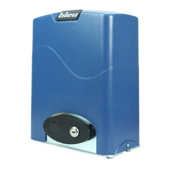
B200
Operatore per cancelli scorrevoli
Operator for sliding gates
Opérateur pour portails coulissants
Automatismo para cancelas correderas
Distributed by SEA S.p.A.
Zona industriale 64020 S.ATTO Teramo - (ITALY)
Tel. +39 0861 588341 r.a. Fax +39 0861 588344
www.bleuteam.it
info@bleuteam.it
67411305
Rev.07 - 04/2016
1
Publicité
Table des Matières

Manuels Connexes pour SEA bleu B200


Sommaire des Matières pour SEA bleu B200
- Page 1 B200 Operatore per cancelli scorrevoli Operator for sliding gates Opérateur pour portails coulissants Automatismo para cancelas correderas Distributed by SEA S.p.A. Zona industriale 64020 S.ATTO Teramo - (ITALY) Tel. +39 0861 588341 r.a. Fax +39 0861 588344 www.bleuteam.it info@bleuteam.it 67411305...
-
Page 2: Informazioni Di Sicurezza Importanti
B200 ISTRUZIONI DI MONTAGGIO E COLLEGAMENTO Italiano 1. INTRODUZIONE Leggere attentamente le istruzioni prima di procedere. Scheda elettronica a microprocessore per controllo operatore. Tastiera a chiave / Interfaccia con un tasto. Gestione fotocellula infrarossi. L’utente può selezionare la funzione Auto-close. Sblocco manuale a chiave in caso di emergenza. - Page 3 Italiano 4. INSTALLAZIONE PARTI MECCANICHE Il B200 è un operatore per cancelli con peso fino a 600 Kg e di lunghezza pari a 8m / 12 m. L'operatore funziona forzando la cremagliera tramite un ingranaggio di azionamento. L'operatore deve essere installato all'interno del cancello. Fig.1 Installazione tipica 6) Lampeggiatore...
- Page 4 Italiano Operatore Ingranaggio Dado Rondella molla Rondella Dado Piano stradale 50 mm Fondazione Alimentazione Nota: ove possibile rialzare il motoriduttore di almeno 50 mm. Finecorsa magnetico Fig.2 Base dell’operatore (vedi Fig.3) Dopo che il calcestruzzo si è indurito, montare la base dell'operatore sulla piattaforma di cemento. Verificare che la base sia ben livellata.
- Page 5 Italiano Cremagliera in acciaio Fig.5 Cremagliera in plastica Fig.6 Cancello scorrevole Magnete Lamierino finecorsa Cremagliera Ingranaggio Finecorsa magnetico Fig.7 Finecorsa magnetico Fig.8 67411305 Rev.07 - 04/2016...
- Page 6 Italiano Lamierini finecorsa regolabili con fissaggio sul cancello (OPZIONALE) Catena Fig.9 67411305 Rev.07 - 04/2016...
- Page 7 Italiano 6. ASSEMBLAGGIO DELLA CATENA L'assemblaggio delle parti principali dell'operatore a catena è illustrato in Figura 10. Fig. 12 Fig. 10 Nelle figure 11 e 12 è mostrata la corretta installazione dell’operatore su cancello rispettivamente aperto e chiuso, la corsa obbligatoria della catena è...
- Page 8 N.B. IL COSTRUTTORE NON PUÒ CONSIDERARSI RESPONSABILE PER EVENTUALI DANNI CAUSATI DA USI IMPROPRI, ERRONEI ED IRRAGIONEVOLI. BLEU by SEA si riserva il diritto di apportare le modifiche o variazioni che ritenesse opportune ai propri prodotti e/o al presente manuale senza alcun obbligo di preavviso.
-
Page 9: Important Safety Information
B200 English MOUNTING AND CONNECTING INSTRUCTIONS 1. INTRODUCTION Please read the instructions carefully before proceeding. Electronic control unit with microswitch for operator’s control Keypad / single button interface. Infrared photocell management . User can select Auto-close function. Manual key release for emergency purposes. 2. -
Page 10: Mechanical Installation
English 4. MECHANICAL INSTALLATION The B200 is an operator for gates with a weight of max. 600 Kg and a length of max. 8m / 12 m. The gate operator operates by forcing a drive rack by a drive gear. The gate operator must be installed on the inside of the gate. -
Page 11: Adjustment
English Gate operator Pinion Spring washer Plain washer Street level 50 mm Foundation Input power Note: Where possible raise the motor of at least 50 mm. Magnetic limit switch Fig.2 Operator base (see Fig.3) After the concrete has hardened, mount the gate operator base to the concrete pad. Verify that the base is properly leveled. Using bolts and washers mount the gate operator to the base and insert the cover. - Page 12 English Steel rack Fig.5 Plastic rack Fig.6 Sliding gate Magnet Limit sheet Rack Pinion Magnetic limit switch Fig.7 Magnetic limit switch Fig.8 67411305 Rev.07 - 04/2016...
- Page 13 English Adjustable limit switch laminations with gate fixing (OPTIONAL) Chain Fig.9 67411305 Rev.07 - 04/2016...
- Page 14 English 6. ASSEMBLING OF THE CHAIN SYSTEM The assembling of the main parts which include the whole chain automation is illustrated in Fig. 10. Fig. 12 Fig. 10 In the pictures 11 and 12 it is possible to see the correct installation with opened and closed gate respectively;...
-
Page 15: Packing List
Bleu by SEA can not be deemed responsible for any damage or accident caused by product breaking, being damages or accidents due to a failure to comply with the instructions herein. The guarantee will be void and the manufacturer responsibility will be nullified if original Bleu by SEA spare parts are not being used. SAFETY PRECAUTIONS: All electrical work and the choice of the operating logic should conform to current regulations. -
Page 16: Importantes Consignes De Securite
B200 Français INSTRUCTIONS DE MONTAGE ET CONNEXION 1. INTRODUCTION Lisez attentivement les instructions avant de commencer. Armoire électronique avec microprocesseur pour le contrôle de l'opérateur. Sélecteur à clé / interface avec touche. Gestion photocellule à infrarouge. L'utilisateur peut sélectionner la fonction Auto-close. Déverrouillage à... -
Page 17: Installation Parties Mecaniques
Français 4. INSTALLATION PARTIES MECANIQUES Le B200 est un opérateur pour portails jusqu'à 600 kg et d’une longueur de 8 m / 12 m. L'opérateur travaille en forçant la cremaillière avec d'un pignon d'entraînement. L'opérateur doit être installé à l'intérieur du portail. Fig.1 Installation standard 6) Clignoteur... - Page 18 Français Opérateur Pignon Ecrou Rondelle ressort Rondelle Ecrou Niveau chaussée 50 mm Fondation Alimentation Remarque: Si c’est possible soulevez le moteur d’au moins 50mm. Fin de course magnétique Fig.2 Base de l'opérateur (voir Fig.3) Après que le béton ait durci, montez la base de l'opérateur sur la plate-forme en béton. Assurez-vous que la base soit nivelée. Installez l’opérateur sur la base à...
- Page 19 Français Cremaillere en acier Fig.5 Cremaillere en plastique Fig.6 Portail coulissant Aimant Laminations fin de course Crémaillière Pignon Fin de course magnétique Fig.7 Fin de course magnétique Fig.8 67411305 Rev.07 - 04/2016...
- Page 20 Français Laminations fin de course réglable avec fixation sur vantail (OPTIONAL) Chaîne Fig.9 67411305 Rev.07 - 04/2016...
-
Page 21: Montage De La Chaine
Français 6. MONTAGE DE LA CHAINE L'assemblage des pièces principales de l'opérateur à chaîne est illustré sur la figure 10. Fig. 12 Fig. 10 Sur les figures 11 et 12, vous pouvez voir l'installation correcte avec portail respectivement ouvert et fermé, la course nécessaire de la chaîne est dans le groupe pignon et ne doit pas être modifiée. -
Page 22: Systeme De Deverrouillage
à cause du non respect des instructions contenues dans ce manuel. La non utilisation des pièces de rechange originales BLEU by SEA annule la garantie et la responsabilité du constructeur relative à la sécurité (en se référant à... -
Page 23: Datos Tecnicos
2. INFORMACIONES DE SEGURIDAD IMPORTANTES Leer cuidadosamente las siguientes instrucciones de precaucion y seguridad antes de instalar y usar este automatismo. Asegurarse que la tensión de alimentación, AC230V o AC115V, del operador, sea la adecuada a la alimentación de la red eléctrica. - Page 24 Antes de iniciar la instalación verificar que todas las partes de la cancela, fijas y mobiles, tengan una estructura fuerte y sin deformaciones, además asegurarse de que : a) La hoja sea rígida y compacta; b) La guìa inferior esté perfectamente recta, horizontal y sin obstáculos que puedan impedir la circulación de la cancela;...
- Page 25 - Desbloquear el automatismo, con la llave, y desplazar manualmente la cancela para predefinir la posición, fijar el soporte a la cremallera y bloquear tirando de la palanca de desbloqueo. Desplazar la cancela electricamente, ajustar el soporte en su posiciòn correcta hasta que la posiciòn de apertura y cierre sea correcta. 67411305...
- Page 26 Español Cremallera de acero Fig.5 Cremallera de plástico Fig.6 Cancela Imán Soporte Cremallera Piñón Final de carrera magnético Fig.7 Final de carrera magnético Fig.8 67411305 Rev.07 - 04/2016...
- Page 27 Español Soportes final de carrera ajustables con montaje en la cancela (OPCIONAL) Cadena Fig.9 67411305 Rev.07 - 04/2016...
- Page 28 Español 6. ENSAMBLAJE DE LA CADENA El ensamblaje de las partes principales del operador està mostrado en Figura 10. Fig. 12 Fig. 10 En las figuras 11 y 12 se mostra la correcta instalación del operador a la cancela respectivamente abierta y cerrada, la carrera obligatoria de la cadena se encuentra al interior del grupo piñón y no tiene que ser modificada.
- Page 29 LEER ATENTAMENTE Bleu by SEA no se hace responsable por daños o accidentes que puedan ser generados por un eventual daño del producto desde el momento que estos sucedan por no respetar las indicaciones de este manual. No utilizar repuestos originales Bleu by SEA ademas de invalidar la garantia, anula la responsabilidad del fabricante relativa a la seguridad.
- Page 30 SEA si intenderanno validi solo dopo la loro accettazione da parte della SEA. I prezzi di vendita sono netti e si intendono per merce resa franco ns. stabilimento in Teramo, esclusi IVA ed imballaggi speciali. La SEA si riserva il diritto di modificare in qualsiasi momento il listino, dando opportuno preavviso alla rete di vendita.
- Page 31 The recognized defects, whatever their nature, shall not produce any responsibility and/or damage claim on the part of the Buyer against SEA. The guarantee is in no case recognized if changes are made to the goods, or in the case of improper use, or in the case of tampering or improper assembly, or if the label affixed by the manufacturer has been removed including the BLEU registered trademark No.
- Page 32 14. Transit through the leaves is allowed only when the gate is fully open. 15. The User must not attempt to repair or to take direct action on the system and must solely contact qualified BLEU by SEA personnel or BLEU by SEA service centers.
- Page 33 3. Este producto fue diseñado y construido exclusivamente para el uso especificado en esta documentación. Cualquier otro uso no expresamente indicado puede afectar la integridad del producto y ser una fuente de peligro. El uso inadecuado es también causa de anulación de la garantía. BLEU by SEA se exime de toda responsabilidad causadas por uso inapropiado o diferente de aquel para el que el sistema automatizado fue producido.
- Page 34 Tel. +39 0861 588341 r.a. Fax +39 0861 588344 Http://www.seateam.com La SEA S.p.A. dichiara che i prodotti sopra citati sono conformi ai requisiti essenziali di sicurezza relativi ai prodotti entro il campo di applicabilità delle seguenti Direttive Comunitarie: SEA S.p.A. declares that the above mentioned products are conforming to the essential safety...
- Page 36 Distributed by SEA S.p.A. Zona industriale 64020 S.ATTO Teramo - (ITALY) Tel. +39 0861 588341 r.a. Fax +39 0861 588344 www.bleuteam.it info@bleuteam.it...