
Sommaire des Matières pour Labex SEUSTER BK-USV
- Page 1 Notöffnung BK-USV / BS-USV BK-USV / BS-USV Emergency Opening Ouverture de secours BK-USV / BS-USV Noodopening BK-USV / BS-USV Nødåpning BK-USV / BS-USV...
- Page 2 DEUTSCH . . . . . . . . . . . . . . . . . . . . . . . . . . . . . . . . . . . . . . . . . . . . . . . . . . . . . . . . . . . . . . . . 3 ENGLISH .
-
Page 3: Table Des Matières
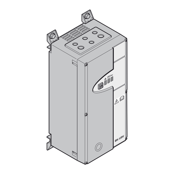
DEUTSCH Inhaltsverzeichnis Geräteansichten der BK-USV / BS-USV Geräteansichten der BK-USV / BS-USV ..3 BK-USV BS-USV Wichtige Sicherheitshinweise ....4 Lagerung / Wartung . -
Page 4: Wichtige Sicherheitshinweise
DEUTSCH Lagerung / Wartung Wichtige Sicherheitshinweise Ist eine längere Lagerung vorgesehen, muss die USV vollständig aufgeladen werden. Um einen guten Batteriezustand Nach vorheriger und aufmerksamer Lektüre der vorliegenden Bedienungsanleitung kann die BK-USV / BS-USV zu erhalten, muss alle 6 Monate ein vollständiger Lade- / Entladezyklus vorgenommen werden. Notstromversorgung für Schnelllauftore von einer elektrischen Fachkraft gemäß... -
Page 5: Installation Und Inbetriebnahme Bk-Usv
DEUTSCH 5 .1 Installation und Inbetriebnahme BK-USV ACHTUNG Niemals die Netzsteckverbinder X0 und X2 der BK-USV zusammenstecken . Das Gerät kann dadurch irreparabel zerstört werden . Motorstrom an der Torsteuerung optimieren. Dazu P 910 = 2 einstellen, um den Motorstrom im Display anzeigen zu lassen. -
Page 6: Montage Der Bs-Usv
DEUTSCH Montage der BS-USV Demontage-/Montage Eingreifschutz BS-USV 6 .1 Installation und Inbetriebnahme BS-USV ACHTUNG Niemals die Adern des Netzeinganges I/P-L, I/P-N mit denen des Netzausganges O/P-L, O/P-N zusammenklemmen . Das Gerät kann dadurch irreparabel zerstört werden . Motorstrom an der Torsteuerung optimieren. Dazu P 910 = 2 einstellen, um den Motorstrom im Display anzeigen zu lassen. -
Page 7: Anzeigen Und Alarm
DEUTSCH Technische Daten (siehe Bild 1) BS-USV ➀ Steuerung am Hauptschalter abschalten und Schaltschrank öffnen. BS-USV am STAND-BY Schalter Eingang Spannung 230 V + 20 % – 25 % (172 – 276 V) ausschalten. Netzversorgung – siehe Schaltplan – ausschalten. ➁ ➂ ➃ Entfernen der Batterieanschlusskabel. -
Page 8: Schaltplan Bk-Usv
DEUTSCH Schaltplan BK-USV USV/UPS I/P-L I/P-N O/P-L O/P-N GNYE GNYE H07RN-F Ölflex-110 H07RN-F 800 mm 4x0,5 mm² 3x1,5 mm² 3x1,5 mm² BK 150 FUE H BK 150 FUE-H BK-USV BK 150 FUE-1 BK 150 FUE-1 BK 150 FUE H X14: 11 / 12 X22:50 / 51 BK 150 FUE-1 X16: 31 / 32... -
Page 9: Stückliste
DEUTSCH Stückliste Benennung Menge Bezeichnung Typennummer Artikelnummer Position Bestellnummer Notöffnung BK FUE-1-USV 018320 Akku USV 12 V 65×95×150 SBH 300 013327 Schützaufsatz 2Ö / 2S für Leistungsschütz LA1KN22M 380007 Leistungsschütz, 2Ö / 2S LC1K09008P7 380017 Buchse 4 plg mit Leitung L20 09 2448 320 04 016305 Stecker 4 plg Leitung L1200 016306 Konformitätserklärung CE-Konformitätserklärung... -
Page 10: Bk-Usv / Bs-Usv Views
ENGLISH Contents BK-USV / BS-USV Views BK-USV / BS-USV Views ....... . 10 BK-USV BS-USV Important Safety Instructions . -
Page 11: Important Safety Instructions
ENGLISH Package Contents for the BK-USV / BS-USV Important Safety Instructions • BK-USV After carefully reading these operating instructions, the BK-USV emergency power supply may be installed and put into – Connecting cable to door control operation by an electrical specialist in accordance with the enclosed circuit documentation. In order to achieve –... -
Page 12: Installation And Initial Start-Up Bk-Usv
ENGLISH 5 .1 Installation and Initial Start-Up BK-USV ATTENTION Never plug together the X0 and X2 power connectors in the BK-USV . This may damage the device beyond repair . Optimise the motor current on the door control. To do this, set P 910 = 2 to view the motor current in the display. Use P 140 to set the motor current to the minimum depending on the normal mains voltage. -
Page 13: Fitting The Bs-Usv
ENGLISH Fitting the BS-USV Dismantling / fitting trap guard BS-USV 6 .1 Installation and Initial Start-Up of the BS-USV ATTENTION Never clamp the wires of the power input I / P-L and I / P-N with those of the power output O / P-L and O / P-N . This may damage the device beyond repair . -
Page 14: Displays And Alarms
ENGLISH Technical data (see Figure 1) BS-USV Switch off the control at the main switch and open the switch box. Switch off the BS-USV ➀. Input Voltage 230 V + 20 % – 25 % (172 – 276 V) with the STAND-BY switch Switch off the power supply – see wiring diagram. ➁... -
Page 15: Wiring Diagram Bk-Usv
ENGLISH Wiring diagram BK-USV USV/UPS I/P-L I/P-N O/P-L O/P-N GNYE GNYE H07RN-F Ölflex-110 H07RN-F 800 mm 4x0,5 mm² 3x1,5 mm² 3x1,5 mm² BK 150 FUE H BK 150 FUE-H BK-USV BK 150 FUE-1 BK 150 FUE-1 BK 150 FUE H X14: 11 / 12 X22:50 / 51 BK 150 FUE-1... -
Page 16: Parts List
ENGLISH Parts list Designation Type number Article number Quantity Designation Position Order number Notöffnung BK FUE-1-USV 018320 Akku USV 12 V 65×95×150 SBH 300 013327 Schützaufsatz 2Ö / 2S für Leistungsschütz LA1KN22M 380007 Leistungsschütz, 2Ö / 2S LC1K09008P7 380017 Buchse 4 plg mit Leitung L20 09 2448 320 04 016305 Stecker 4 plg Leitung L1200... -
Page 17: Vues De La Bk-Usv / Bs-Usv
FRANÇAIS Table des matières Vues de la BK-USV / BS-USV Vues de la BK-USV / BS-USV ......17 BK-USV BS-USV Consignes de sécurité... -
Page 18: Consignes De Sécurité Importantes
FRANÇAIS Stockage / Maintenance Consignes de sécurité importantes Si un stockage à long terme est prévu, la BK-USV doit être entièrement chargée. Pour maintenir les batteries Après avoir lu attentivement les présentes instructions d’utilisation, un électricien professionnel peut installer et mettre état, un cycle de chargement / déchargement complet doit être effectué... -
Page 19: Installation Et Mise En Service De La Bk-Usv
FRANÇAIS 5 .1 Installation et mise en service de la BK-USV ATTENTION Ne raccordez jamais les connecteurs de fiches secteur X0 et X2 de la BK-USV ensemble . Cette opération peut provoquer une destruction irréparable de l’appareil . Optimisez le courant moteur de la commande de porte. Pour cela, réglez P 910 sur 2, afin d’afficher le courant moteur à... -
Page 20: Montage De La Bs-Usv
FRANÇAIS Montage de la BS-USV Montage / Démontage de la protection latérale BS-USV 6 .1 Installation et mise en service de la BS-USV ATTENTION Ne reliez jamais les conducteurs des entrées secteur I/P-L et I/P-N à ceux des sorties secteur O/P-L et O/P-N . Cette opération peut causer une destruction irréparable de l’appareil . -
Page 21: Affichages Et Alarme
FRANÇAIS Données techniques (voir Figure 1) BS-USV Eteignez la commande à partir du sectionneur multipolaire et ouvrez le boîtier de commande. Eteignez la BS-USV ➀ Entrée Tension 230 V + 20 % – 25 % (172 – 276 V) à l’aide de l’interrupteur de veille . -
Page 22: Schéma Électrique Bk-Usv
FRANÇAIS Schéma électrique BK-USV USV/UPS I/P-L I/P-N O/P-L O/P-N GNYE GNYE H07RN-F Ölflex-110 H07RN-F 800 mm 4x0,5 mm² 3x1,5 mm² 3x1,5 mm² BK 150 FUE H BK 150 FUE-H BK-USV BK 150 FUE-1 BK 150 FUE-1 BK 150 FUE H X14: 11 / 12 X22:50 / 51 BK 150 FUE-1... -
Page 23: Liste De Pièces
FRANÇAIS Liste de pièces Désignation Numéro de type Numéro d’article Quantité Désignation Position Numéro de commande Notöffnung BK FUE-1-USV 018320 Akku USV 12 V 65×95×150 SBH 300 013327 Schützaufsatz 2Ö / 2S für Leistungsschütz LA1KN22M 380007 Leistungsschütz, 2Ö / 2S LC1K09008P7 380017 Buchse 4 plg mit Leitung L20 09 2448 320 04 016305 Stecker 4 plg Leitung L1200... - Page 24 NEDERLANDS Inhoudsopgave Apparaataanzichten van de BK-USV / BS-USV Apparaataanzichten van BK-USV BS-USV de BK-USV / BS-USV ........24 Belangrijke veiligheidsinstructies .
-
Page 25: Belangrijke Veiligheidsinstructies
NEDERLANDS Opslag / onderhoud Belangrijke veiligheidsinstructies Wanneer een langere opslag is voorzien, moet de USV volledig worden opgeladen. Om de batterijen in goede staat Na de onderhavige bedieningshandleiding van tevoren aandachtig te hebben gelezen, houden, moeten deze elke 6 maanden volledig worden opgeladen en ontladen. ... -
Page 26: Installatie En Ingebruikname Bk-Usv
NEDERLANDS 5 .1 Installatie en ingebruikname BK-USV LET OP Steek nooit de aansluitstekkers X0 en X2 van de BK-USV in elkaar . Het apparaat kan daardoor onherstelbaar worden vernield . Optimaliseer de motorstroom op de deurbesturing. Stel daarvoor P 910 = 2 in, om de motorstroom display te laten weergeven. -
Page 27: Montage Van De Bs-Usv
NEDERLANDS Montage van de BS-USV Demontage / montage ingrijpbeveiliging BS-USV 6 .1 Installatie en ingebruikname BS-USV LET OP Klem nooit de aders van de netingang I/P-L, I/P-N samen vast met die van de netuitgang O/P-L, O/P-N . Het apparaat kan daardoor onherstelbaar worden vernield . Optimaliseer de motorstroom op de deurbesturing. Stel daarvoor P 910 = 2 in, om de motorstroom display te laten weergeven. -
Page 28: Weergaves En Alarm
NEDERLANDS Technische gegevens (Zie afbeelding 1) BS-USV Schakel de besturing uit met de hoofdschakelaar en open de schakelkast. Schakel de BS-USV ➀ Ingang Spanning 230 V + 20 % – 25 % (172 – 276 V) uit met de STAND-BY-schakelaar . Netspanning – zie schakelschema – inschakelen.. ➁ ➂ ➃ Verwijder de batterijaansluitkabel. -
Page 29: Schakelschema Bk-Usv
NEDERLANDS Schakelschema BK-USV USV/UPS I/P-L I/P-N O/P-L O/P-N GNYE GNYE H07RN-F Ölflex-110 H07RN-F 800 mm 4x0,5 mm² 3x1,5 mm² 3x1,5 mm² BK 150 FUE H BK 150 FUE-H BK-USV BK 150 FUE-1 BK 150 FUE-1 BK 150 FUE H X14: 11 / 12 X22:50 / 51 BK 150 FUE-1 X16: 31 / 32... -
Page 30: Stuklijst
NEDERLANDS Stuklijst Benaming Typenummer Artikelnummer Hoeveelheid Benaming Positie Bestelnummer Notöffnung BK FUE-1-USV 018320 Akku USV 12 V 65×95×150 SBH 300 013327 Schützaufsatz 2Ö / 2S für Leistungsschütz LA1KN22M 380007 Leistungsschütz, 2Ö / 2S LC1K09008P7 380017 Buchse 4 plg mit Leitung L20 09 2448 320 04 016305 Stecker 4 plg Leitung L1200 016306 Conformiteitsverklaring CE-conformiteitsverklaring... - Page 31 NORSK Innhold Illustrasjoner for enheten BK-USV / BS-USV Illustrasjoner for enheten BK-USV BS-USV BK-USV / BS-USV ......... . . 27 Viktige sikkerhetsinstrukser .
-
Page 32: Viktige Sikkerhetsinstrukser
NORSK Lagring / vedlikehold Viktige sikkerhetsinstrukser Dersom enheten for avbruddsfri strømforsyning skal lagres over lengre tid, kreves det en fullstendig opplading. Etter at denne bruksanvisningen er nøye lest, kan nødstrømforsyningen BK-USV for hurtigporter installeres For å opprettholde optimal batteritilstand, må enheten lades helt ut og lades opp fullstendig hver 6. måned. av en faglært elektriker ifølge vedlagt koblingsskjema og tas i bruk. -
Page 33: Installasjon Og Igangsetting Bk-Usv
NORSK 5 .1 Installasjon og igangsetting BK-USV Stikkontaktene X0 og X2 til BK-USV må aldri kobles sammen . På denne måten kan enheten ødelegges uten mulighet for reparasjon . Optimer motorstrømmen for portstyringen. Dertil innstilles P 910 = 2 for at motorstrømmen skal vises i displayet. Avhengig av vanlig nettspenning reduseres motorstrømmen med P 140 til minimum. -
Page 34: Montering Av Bs-Usv
NORSK Montering av BS-USV Demontering / montering inngrepsvern BS-USV 6 .1 Installasjon og igangsetting BS-USV Tilførselsledningens lederne I/P-L, I/P-N må aldri koples til utgående kablers ledere O/P-L, O/P-N . Dette kan føre til irreparable skader på enheten . Optimer motorstrømmen for portstyringen. Dertil innstilles P 910 = 2 for at motorstrømmen skal vises i displayet. Avhengig av vanlig nettspenning reduseres motorstrømmen med P 140 til minimum. -
Page 35: Funksjonsforløp Portstyring Med Avbruddsfri
NORSK Tekniske data (se bilde 1) BS-USV ➀ Frakople styringen med hovedbryteren og åpne koplingsskapet. Frakople BS-UPS med STAND-BY-bryteren Inngang Spenning 230 V + 20 % – 25 % (172 – 276 V) Slå på – se koplingsskjema – strømforsyningen. ➁ ➂ ➃... - Page 36 NORSK Koblingsskjema BK-USV USV/UPS I/P-L I/P-N O/P-L O/P-N GNYE GNYE H07RN-F Ölflex-110 H07RN-F 800 mm 4x0,5 mm² 3x1,5 mm² 3x1,5 mm² BK 150 FUE H BK 150 FUE-H BK-USV BK 150 FUE-1 BK 150 FUE-1 BK 150 FUE H X14: 11 / 12 X22:50 / 51 BK 150 FUE-1 X16: 31 / 32...
-
Page 37: Stykkliste
NORSK Stykkliste Benevnelse Typenummer Mengde Betegnelse Artikkelnummer Posisjon Bestillingsnummer Notöffnung BK FUE-1-USV 018320 Akku USV 12 V 65×95×150 SBH 300 013327 Schützaufsatz 2Ö / 2S für Leistungsschütz LA1KN22M 380007 Leistungsschütz, 2Ö / 2S LC1K09008P7 380017 Buchse 4 plg mit Leitung L20 09 2448 320 04 016305 Stecker 4 plg Leitung L1200 016306 Samsvarserklæring CE-samsvarserklæring... - Page 38 016 576 / BK-USV RE / 01.2013...
- Page 39 016 576 / BK-USV RE / 01.2013...
- Page 40 Weitergabe sowie Vervielfältigung dieses Doku ments, Ver- wertung und Mitteilung seines Inhalts sind verboten, soweit nicht ausdrücklich gestattet. Zuwiderhandlungen ver- pflichten zu Schadenersatz. Alle Rechte für den Fall der Patent-, Gebrauchs muster- oder Geschmacks- mustereintragung vorbe halten. Änderungen vorbe halten. Dissemination as well as duplication of this document and the use and communication of its content are prohibited unless explicitly permitted.