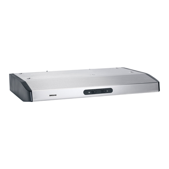
Broan ESB10 Directives D'installation, D'utilisation Et D'entretien
Masquer les pouces
Voir aussi pour ESB10:
- Directives d'installation, d'utilisation et d'entretien (36 pages) ,
- Instructions d'installation (36 pages)
Table des Matières
Publicité
Les langues disponibles
Les langues disponibles
Liens rapides
RANGE HOOD
INSTALLATION INSTRUCTIONS - USE AND CARE
HB0062
MODELS ESB10, QDE, AND ESC270
INTENDED FOR DOMESTIC COOKING ONLY
!
!
READ AND SAVE THESE INSTRUCTIONS
INSTALLER: LEAVE THIS MANUAL WITH HOMEOWNER.
HOMEOWNER: CLEANING AND OPERATION INFORMATION
ON PAGES 9 AND 10.
REGISTER YOUR PRODUCT ON LINE AT: www.venmar.ca
SV06727 rev. D
Publicité
Chapitres
Table des Matières

Manuels Connexes pour Broan ESB10


Sommaire des Matières pour Broan ESB10
- Page 1 RANGE HOOD INSTALLATION INSTRUCTIONS - USE AND CARE HB0062 MODELS ESB10, QDE, AND ESC270 INTENDED FOR DOMESTIC COOKING ONLY READ AND SAVE THESE INSTRUCTIONS INSTALLER: LEAVE THIS MANUAL WITH HOMEOWNER. HOMEOWNER: CLEANING AND OPERATION INFORMATION ON PAGES 9 AND 10.
- Page 2 WARNING WARNING TO REDUCE THE RISK OF FIRE, ELECTRIC TO REDUCE THE RISK OF INJURY TO PERSONS SHOCK OR INJURY TO PERSONS, OBSERVE THE IN THE EVENT OF A RANGE TOP GREASE FIRE, FOLLOWING: OBSERVE THE FOLLOWING*: 1. Use this unit only in the manner intended by the 1.
-
Page 3: Table Des Matières
ABOUT THIS MANUAL Please take note this manual uses the following symbols to emphasize particular information: WARNING Identifies an instruction which, if not followed, might cause serious personal injuries including possibility of death. CAUTION Denotes an instruction which, if not followed, may severely damage the unit and/or its components. NOTE: Indicates supplementary information needed to fully complete an instruction. -
Page 4: Install Ductwork
1. INSTALL DUCTWORK Plan where and how the ductwork will be installed. Install proper-sized ductwork, elbow(s) and roof or wall cap for the type of blower you are installing. If using 6’’ (150 mm) round ducts, use a transition. Use 2’’ (50 mm) metal foil duct tape to seal joints. Roof cap Roof cap 6”... -
Page 5: Prepare The Installation
3. PREPARE THE INSTALLATION Make sure the following items are included: - Hood - Filters (2) - Adapter/damper assembly 3¼’’ x 10’’ (located inside the hood, under the bottom panel) - Compact fluorescent lamps (120 V, 13 W, PLC13, 2700 K with G24q-1 base) (packed behind the light diffuser) - Parts bag (located inside the hood, under the bottom panel) including: 1 wire clamp, 5 no. -
Page 6: Install The Adapter/Damper
4. PREPARE THE HOOD (CONT’D) Punch out the appropriate electrical knock-out hole. Using a long nose pliers, remove the knock-out for the chosen opening (vertical on top or horizontal at the back of the hood). See figures below. ERTICAL DISCHARGE ORIZONTAL DISCHARGE HD0153 5. -
Page 7: Install The Hood
5. INSTALL THE ADAPTER/DAMPER (CONT’D) ERTICAL DISCHARGE For a vertical discharge installation only, leave the foldable flange (C) of the adapter/damper as is. This flange must be located towards the front of the hood. See beside. HO0057 LL INSTALLATIONS Using two 1/2” screws, secure the adapter/damper to the top or back of the hood. -
Page 8: Reinstall Bottom Panel And Filters
8. REINSTALL BOTTOM PANEL AND FILTERS Reinstall the bottom panel, using the retaining screw previously removed in step 4 plus 4 others from parts bag. Refer to illustration beside. Then, reinstall filters. HO0092 9. FLUORESCENT LAMPS WARNING This hood has fluorescent lamps containing mercury. Dispose of appropriately, according to local laws and requirements. This range hood must use compact fluorescent lamps (120 V, 13 W, PLC13, 2700 K with G24q-1 base) (included). -
Page 9: Cleaning
10. CLEANING The grease filters, bottom panel, intake ring (A) and blower wheel (B) should be cleaned frequently. Use a warm detergent solution. The grease filters, intake ring and blower wheel are dishwasher safe. Clean all-metal filters in the diswasher using a non-phosphate detergent. Discoloration of the filter may occur if using phosphate detergents, or as a result of local water conditions —... -
Page 10: Operation
11. OPERATION Always turn on the hood before beginning cooking in order to establish an air flow in the kitchen. Let the blower run for a few minutes to clear the air after turning off the range. OCKER WITCH ONTROL HC0031 A. -
Page 11: Service Parts
12. SERVICE PARTS MODEL ESB10 KEY PART DESCRIPTION QTY. 13296 DAPTER AMPER 03623 LUORESCENT LAMP 01752 IGHT DIFFUSER 01988 LOWER WHEEL 01757 NLET RING 14131 ICROMESH FILTER THE PAIR SV06727 & NSTALLATION USER MANUAL : (1) , (2) ARDWARE BAG... - Page 12 12. SERVICE PARTS MODEL QDE HL0095 PART DESCRIPTION QTY. SV13296 A DAPTER AMPER SV15434 R OCKER SWITCH WHITE PAIR OVERLAY WHITE SV15433 R OCKER SWITCH BLACK PAIR OVERLAY BLACK SV03623 F LUORESCENT LAMP SV01752 L IGHT DIFFUSER SV01765 M OTOR SV01988 B LOWER WHEEL SV16119 B...
-
Page 13: Modèles Esb10, Qde Et Esc270
HOTTES DE CUISINIÈRE DIRECTIVES D’INSTALLATION, D’UTILISATION ET D’ENTRETIEN HB0062 MODÈLES ESB10, QDE ET ESC270 CONÇUES UNIQUEMENT POUR LA CUISSON DOMESTIQUE VEUILLEZ LIRE ET CONSERVER CES DIRECTIVES INSTALLATEUR : LAISSEZ CE GUIDE AU PROPRIÉTAIRE. PROPRIÉTAIRE : DIRECTIVES D’ENTRETIEN ET DE FONCTIONNEMENT EN PAGES 21 et 22. - Page 14 AVERTISSEMENT AVERTISSEMENT AFIN DE RÉDUIRE LES RISQUES D’INCENDIE, AFIN D’ÉVITER TOUS RISQUES DE BLESSURE D’ÉLECTROCUTION OU DE BLESSURES CORPORELLES, DANS LE CAS D’UN FEU DE CUISINIÈRE, SUIVEZ SUIVEZ LES DIRECTIVES SUIVANTES : CES DIRECTIVES* : 1. N’utilisez cet appareil que de la façon prévue par le 1.
-
Page 15: À Propos De Ce Guide
À PROPOS DE CE GUIDE Ce guide utilise les symboles suivants afin d’accentuer les informations qui s’y trouvent : AVERTISSEMENT Identifie une instruction qui, si elle n’est pas suivie, peut causer de graves blessures corporelles ou la mort. ATTENTION Identifie une instruction qui, si elle n’est pas suivie, peut gravement endommager l’appareil et/ou ses pièces. NOTE : Indique une information supplémentaire afin de réaliser complètement une instruction. -
Page 16: Installation Des Conduits
1. INSTALLATION DES CONDUITS Planifier à quel endroit et de quelle façon seront installés les conduits. Installer des conduits de format adéquat, coude(s) et capuchon de mur ou de toit selon le genre de ventilateur utilisé. Si des conduits ronds de 6 po (150 mm) sont utilisés, se servir d’une transition. Sceller les joints avec du ruban adhésif en toile de 2 po (50 mm) de largeur. -
Page 17: Préparation De Linstallation
3. PRÉPARATION DE L’INSTALLATION S’assurer que les articles suivants sont inclus : - Hotte - Filtres (2) - Adaptateur/volet 3¼ po x 10 po (à l’intérieur de la hotte, sous le panneau inférieur) - Ampoules fluorescentes compactes (120 V, 13 W, PLC13, 2700 K avec culot G24q-1) (emballées derrière le diffuseur lumière) - Sac de pièces (à... -
Page 18: Installation De Ladaptateur Volet
4. PRÉPARATION DE LA HOTTE (SUITE) Défoncer l’ouverture préamorcée prévue pour le fil d’alimentation électrique. À l’aide d’une pince à long bec, retirer l’overture préamorcée choisie (évacuation verticale sur le dessus ou horizontale à l’arrière de la hotte). Voir les illustrations ci-dessous. É... -
Page 19: Installation De La Hotte
5. INSTALLATION DE L’ADAPTATEUR/VOLET (SUITE) É VACUATION VERTICALE Pour une installation avec évacuation verticale seulement, laisser le rebord pliable (C) tel quel. Installer l’adaptateur/volet de façon à ce que ce rebord soit dirigé vers l’avant de la hotte. Voir ci-contre. HO0057 OUTES LES INSTALLATIONS À... -
Page 20: Réinstallation Du Panneau Inférieur
8. RÉINSTALLATION DU PANNEAU INFÉRIEUR Réinstaller le panneau inférieur et le fixer à la hotte à l’aide de la vis retirée précédemment à l’étape 4 plus quatre autres provenant du sac de pièces. Voir ci-contre. Puis, réinstaller les filtres. HO0092 9. -
Page 21: Entretien
10. ENTRETIEN Les filtres, le panneau inférieur, l’anneau d’admission (A) et la roue (B) de ventilateur doivent être nettoyés régulièrement. Utiliser de l’eau chaude additionnée de détergent. Les filtres, anneau et roue de ventilateur sont lavables au lave-vaisselle. Nettoyer les filtres métalliques au lave-vaisselle avec un détergent sans phosphate. -
Page 22: Fonctionnement
11. FONCTIONNEMENT Toujours mettre en marche la hotte avant de commencer la cuisson afin d’établir une circulation d’air dans la cuisine. Aussi, laisser la hotte fonctionner quelques minutes après l’arrêt de la cuisinière afin de nettoyer l’air. OMMANDE À INTERRUPTEURS À BASCULE HC0031 A. -
Page 23: Pièces De Remplacement
12. PIÈCES DE REMPLACEMENT MODÈLE ESB10 N° PIÈCE DESCRIPTION QTÉ Réf. N° 13296 DAPTATEUR OLET 03623 AMPE FLUORESCENTE 01752 IFFUSEUR LUMIÈRE 01988 OUE DE VENTILATEUR 01757 ’ NNEAU D ADMISSION 14131 « M » ( ILTRE ICROMESH LA PAIRE SV06727 ’... - Page 24 12. PIÈCES DE REMPLACEMENT MODÈLE QDE HL0095 N° PIÈCE Réf. N°. DESCRIPTION QTÉ SV13296 A DAPTATEUR OLET SV15434 I NTERRUPTEUR À BASCULE BLANC PAIRE DÉCALQUE BLANC SV15433 I NTERRUPTEUR À BASCULE NOIR PAIRE DÉCALQUE NOIR SV03623 L AMPE FLUORESCENTE SV01752 D IFFUSEUR LUMIÈRE SV01765 M OTEUR...
- Page 25 CAMPANAS DE COCINA INSTRUCCIONES DE INSTALACIÓN - UTILIZACIÓN Y CUIDADO HB0062 MODELOS ESB10, QDE Y ESC270 EXCLUSIVAMENTE PARA COCINAS DOMÉSTICAS LEA Y CONSERVE ESTAS INSTRUCCIONES INSTALADOR: ENTREGUE ESTE MANUAL AL PROPIETARIO DE LA CASA. PROPIETARIO: INFORMACIÓN SOBRE LIMPEIZA Y FUNCIONAMIENTO EN LAS PÁGINAS 33 y 34.
- Page 26 ADVERTENCIA ADVERTENCIA PARA REDUCIR EL RIESGO DE INCENDIO, PARA REDUCIR EL RIESGO DE LESIONES DESCARGA ELÉCTRICA O LESIÓN CORPORAL, CORPORALES EN EL CASO DE QUE ARDA LA RESPETE LAS SIGUIENTES INDICACIONES: GRASA EN LA PARTE SUPERIOR DE LA COCINA, SIGA ESTAS INDICACIONES*: Utilice este aparato únicamente de la forma en que indica el fabricante.
-
Page 27: Àcerca De Este Manual
ÀCERCA DE ESTE MANUAL Tenga en cuenta que este manual se emplean los siguientes símbolos cuando se quiere insistir en una información determinada: ADVERTENCIA Se refiere a una instrucción que, de no seguirse, podría causar heridas corporales graves e incluso la muerte. PRECAUCIÓN Se refiere a una instrucción que, de no seguirse, podría dañar gravemente el aparato o sus piezas. -
Page 28: Instalación De Los Tubos
1. INSTALACIÓN DE LOS TUBOS Planifique el lugar y la forma en que se instalarán los tubos. Instale tubos, codo(s) y tapa de techo o de pared de tamaños adecuados, según el ventilador que vaya a usar. Si utiliza tubos circulares de 6 pulgadas (150 mm), debería usar un cambio de sección. -
Page 29: Preparación De La Instalación
3. PREPARACIÓN DE LA INSTALACIÓN Compruebe que el aparato viene con los siguientes: - Campana - Filtros (2) - Conjunto del adaptador/dispositivo de cierre de 3¼’’ x 10’’ (ubicado en la campana, bajo el tablero inferior) - Bombillas fluorescentes (120 V, 13 W, PLC13, 2700 K con base G24q-1) (lámparas fluorescentes embaladas detrás el difusor de luz) - Bolsa con piezas (ubicado en la campana, bajo el tablero inferior), que comprende: (1) abrazadera de cable, (5) tornillos de doble rosca n.°... -
Page 30: Instalación Del Adaptador/Dispositivo De Cierre
4. PREPARACIÓN DE LA CAMPANA (CONTINUACIÓN) Perfore el orificio ciego eléctrico apropiado. Emplee unos alicates de punta larga para retirar la pieza desmontable de la apertura elegida (vertical en la parte superior u horizontal en la parte trasera de la campana). Consulte las singuientes ilustraciones. ESCARGA VERTICAL ESCARGA HORIZONTAL HD0153... -
Page 31: Instalación De La Campana
5. INSTALACIÓN DEL ADAPTADOR/DISPOSITIVO DE CIERRE (CONTINUACIÓN) ESCARGA VERTICAL Para una instalación con descarga vertical solamente, dejar el reborde desplegable (C) tal cual. Colocar el adaptador de tal forma que este reborde es hacia frente a la campana. Véase al lado. HO0057 ODAS LAS INSTALACIÓNES Utilice (2) tornillos de 1/2”, para fijar el adaptador/dispositivo de cierre en la parte... -
Page 32: Reinstalación Del Tablero Inferior
8. REINSTALACIÓN DEL TABLERO INFERIOR Vuelva a instalar el tablero inferior utilizando el tornillo que quitó en la etapa 4 y 4 otros tornillos de la bolsa con piezas, como se ve en la ilustración al lado A continuación, instale los filtros. HO0092 9. -
Page 33: Limpieza
10. LIMPIEZA Los filtros de grasa, el tablero inferior, el anillo de admisión (A) y la rueda del ventilador (B) deben limpiarse con frecuencia. Utilice una disolución de detergente con agua templada. Los filtros, el anillo de admisión y la rueda del ventilador se pueden lavar en el lavavajillas. -
Page 34: Funcionamiento
11. FUNCIONAMENTO Ponga en marcha siempre la campana antes de empezar a cocinar para generar una corriente de aire en la cocina. Deje en marcha el ventilador unos minutos para renovar el aire una vez que haya apagado la cocina. NTERRUPTORES OSCILANTES HC0031 A. -
Page 35: Piezas
12. PIEZAS MODELO ESB10 N.° N.° DE DESCRIPCIÓN PIEZA 13296 DAPTADOR DISPOSITIVO DE CIERRE 03623 ÁMPARAS FLUORESCENTE 01752 IFUSOR DE LUZ 01988 UEDA DEL VENTILADOR 01757 NILLO DE ENTRADA 14131 ILTROS DE MICROTAMIZ SV06727 ANUAL DE INSTALACIÓN Y DEL USUARIO : (1) OLSA CON PIEZAS METÁLICAS... - Page 36 12. PIEZAS MODELO QDE HL0095 N.° N.° DE PIEZA DESCRIPCIÓN SV13296 A DAPTADOR DISPOSITIVO DE CIERRE SV15434 I NTERRUPTOR BASCULANTE BLANCO CALCO BLANCO SV15433 I NTERRUPTOR BASCULANTE NEGRO CALCO NEGRO SV03623 L ÁMPARAS FLUORESCENTE SV01752 D IFUSOR DE LUZ SV01765 M OTOR SV01988 R UEDA DEL VENTILADOR...