Table des Matières
Publicité
Les langues disponibles
Les langues disponibles
Liens rapides
NATURAL GAS MODELS:
PROPANE GAS MODELS:
SAFETY INFORMATION
WARNING
!
FIRE OR EXPLOSION HAZARD
Failure to follow safety warnings exactly
could result in serious injury, death, or
property damage.
- Do not store or use gasoline or other
fl ammable vapors and liquids in the vicinity of
this or any other appliance.
- WHAT TO DO IF YOU SMELL GAS:
•
Do not try to light any appliance.
•
Do not touch any electrical switch; do not
use any phone in your building.
•
Immediately call your gas supplier from a
neighbour's phone. Follow the gas
supplier's instructions.
•
If you cannot reach your gas supplier, call
the fi re department.
- Installation and service must be performed
by a qualifi ed installer, service agency, or the
supplier.
This appliance may be installed in an aftermarket,
permanently located, manufactured home (USA
only) or mobile home, where not prohibited by
local codes.
This appliance is only for use with the type of gas
indicated on the rating plate. This appliance is
not convertible for use with other gases, unless
a certifi ed kit is used.
INSTALLER:
Leave this manual with the appliance
CONSUMER:
Retain this manual for future reference
Wolf Steel Ltd., 24 Napoleon Rd., Barrie, ON, L4M 0G8 Canada / 103 Miller Drive, Crittenden, Kentucky, USA, 41030
Phone 1 (866) 820-8686 • www.continentalfi replaces.com • hearth@continentalfi replaces.com
$10.00
CDVS280-1NSB / CDVS280-1NE / CS280-1N / CS280-1NE
ADD PRODUCT CODE HERE (TRADE GOTHIC LT STD FONT)
CDVS280-1PSB / CDVS280-1PE / CS280-1P / CS280-1PE
INSTALLATION AND
ADD MANUAL TITLE
OPERATION MANUAL
Model CS280-1 is made up of Model CDVS280-1 and Natural
CERTIFIED TO THE CANADIAN AND AMERICAN NATIONAL STANDARDS:
CSA 2.22 AND ANSI Z21.50 FOR VENTED DECORATIVE GAS APPLIANCES
IF INSTALLATION + OPERATION, ADD SERIAL
CSA /
INTERTEK
LOGO
BARCODE LABEL ON THE OWNER'S MANUAL"
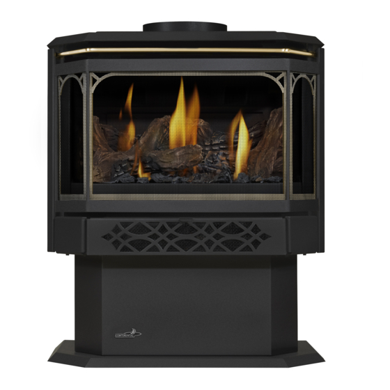
Product Name / Code
Gas Stove Series
(MUST use title from Price Book)
(CDVS280-1 illustrated)
ADD ____ ILLUSTRATED
ADD PRODUCT IMAGE
Vent Adapter Kit GS-150KT
FOR INDOOR USE ONLY
NUMBER LABEL HERE
IF SEPARATE MANUALS, ADD "PLACE
ENGLISH
FRENCH PG. 55
W415-2340 / C / 02.08.21
Publicité
Chapitres
Table des Matières
Dépannage

Manuels Connexes pour Continental Fireplaces CDVS280-1


Sommaire des Matières pour Continental Fireplaces CDVS280-1
- Page 1 This appliance may be installed in an aftermarket, permanently located, manufactured home (USA only) or mobile home, where not prohibited by Model CS280-1 is made up of Model CDVS280-1 and Natural local codes. Vent Adapter Kit GS-150KT This appliance is only for use with the type of gas indicated on the rating plate.
-
Page 2: Safety Information
safety information WARNING DANGER • This appliance is hot when operated and can cause severe burns if contacted. • Any changes or alterations to this appliance or its controls can be dangerous and is prohibited. HOT GLASS WILL CAUSE BURNS. •... - Page 3 safety information WARNING • Do not use a blower insert, heat exchanger insert or other accessory not approved for use with this appliance. • This appliance must not be connected to a chimney fl ue pipe serving a separate solid fuel burning appliance.
-
Page 4: Table Des Matières
fl ame characteristics horizontal installation maintenance vertical installation annual maintenance horizontal air terminal installation - care of glass model CDVS280-1 blower replacement vertical air terminal installation replacement parts appliance vent connection overview natural vent specifi cs millivolt valve train assembly... -
Page 5: General Information
The protective wrap must be removed before operating the appliance. Vented decorative gas appliance: not a source of heat; not for use with solid fuel. rates and effi ciencies CDVS280-1 CS280-1 Altitude (FT) 0-4,500 Max. -
Page 6: General Instructions
general information general instructions WARNING • Always light the pilot, whether for the fi rst time or if the gas supply has run out, with the glass door opened or removed. • Provide adequate clearance for servicing and operating the appliance. •... -
Page 7: Rating Plate Information
The rating plate must remain with the appliance at all times. It must not be removed. This illustration is for reference only. Refer to the rating plate on the appliance for accurate information. mobile home installation - model CDVS280-1 This appliance must be installed in accordance with the manufacturer’s instructions and the Manufactured Home Construction and Safety Standard, Title 24 CFR, Part 3280, in the United States or the Mobile Home Standard, CAN/CSA Z240 MH Series, in Canada. -
Page 8: Dimensions
general information dimensions W415-2340 / C / 02.08.21... -
Page 9: Venting
2.0 venting venting WARNING • Risk of fi re. Maintain specifi ed air space clearances to vent pipe and appliance. • The vent system must be supported every 3’(0.9m) for both vertical and horizontal runs. Use support ring assembly W010- 0067 or equivalent non-combustible strapping to maintain the minimum clearance to combustibles for both vertical and horizontal runs. -
Page 10: Typical Vent Installation
venting These vent kits allow for either horizontal or vertical venting of the appliance. The maximum allowable horizontal run is 20 feet (6.1m). The maximum allowable vertical vent length is 40 feet (12.2m). The maximum number of vent connections is two horizontally or three vertically (excluding the appliance and the air terminal connections) when using fl... -
Page 11: Special Vent Installations
venting special vent installations 2.2.1 periscope termination Use the periscope kit to locate the air termination above grade. The periscope must be installed so that when fi nal grading is completed, the bottom air slot is located a minimum 12” (305mm) above grade. The maximum allowable vent length (including both rise and run) is 10’... -
Page 12: Vent Terminal Clearances
venting vent terminal clearances Covered balcony applications ††* = 3 feet = 2 x ACTUAL (0.9m) (4.6m) note: INSTALLATIONS Wall terminals are for illustration purposes only. Size and shapes may vary. CANADA U.S.A. 12” (30.5cm) 12” (30.5cm) Clearance above grade, veranda porch, deck or balcony. 12”... -
Page 13: Vent Fl Ow Charts
venting vent fl ow charts Top Exit Horizontal Termination Vertical Termination Vertical rise is equal Vertical rise is equal Vertical rise is less Vertical rise is less to or greater than the to or greater than the than horizontal run than horizontal run horizontal run horizontal run... -
Page 14: Horizontal Termination
venting horizontal termination ) < (V Simple venting confi guration (only one 90° elbow) See graph to determine the required vertical rise V for the required horizontal run H 40 (12.2) 39 (11.9) REQUIRED 30 (9.1) VERTICAL RISE IN FEET 20 (6.1) (METERS)V 10 (3.1) - Page 15 venting ) > (V Simple venting configuration (only one 90° elbow) See graph to determine the required vertical rise V the required horizontal run H 150 (3810) 147 (3733.8) REQUIRED VERTICAL RISE IN INCHES 100 (2540) (MILLIMETERS) V 57 (1447.8) 50 (1270) 29 (736.6) 20 (6.1)
-
Page 16: Top Exit Vertical Termination
venting top exit vertical termination ) < (V Simple venting configurations. See graph to determine the required vertical rise V for the required horizontal run H 40 (12.2) 30 (9.1) REQUIRED VERTICAL RISE IN FEET 20 (6.1) (METERS) V 10 (3.1) 3 (0.9) (1.5) (3.1) - Page 17 venting ) > (V Simple venting configurations. See graph to determine the required vertical rise V for the required horizontal run H 20 (6.1) 19 (5.8) REQUIRED VERTICAL RISE IN FEET 10 (3.1) (METERS) V 3 (0.9) (7.6) (9.1) (1.5) (3.1) (4.6) (6.1)
-
Page 18: Vertical Through Existing Chimney
venting vertical through existing chimney WARNING • Risk of fi re. • Co-axial to co-linear venting confi gurations must only be used in a non-combustible chimney or enclosure. Installation in a combustible enclosure could result in a fi re. This appliance is designed to be attached to a 3” (76.2mm) co-linear aluminum fl ex vent system running the full length of a masonry chimney. -
Page 19: Installation
* At a distance of 1" (25mm) from the wall, access to the blower switch, on/off switch or the blower power cord may not be practical. CDVS280-1: HORIZONTAL VENT SECTIONS: A minimum clearance of 2" (51mm) at the top and 1" (25mm) at the bottom and sides of the vent pipe on all horizontal runs is required. -
Page 20: Horizontal Installation
installation 3.1.1 horizontal installation WARNING • The fi restop assembly must be installed with the vent shield to the top. • Terminals must not be recessed into a wall or siding more than the depth of the return fl ange of the mounting plate. -
Page 21: Horizontal Air Terminal Installation - Model Cdvs280
3.1.3 horizontal air terminal installation - model CDVS280-1 Stretch the inner fl ex pipe to the required length taking into account the additional length needed for the fi nished ADD FASTENER TYPE wall surface. Apply a heavy bead of the red RTV silicone... -
Page 22: Vertical Air Terminal Installation
installation 3.1.4 vertical air terminal installation WARNING • Maintain a minimum 2” (51mm) space between the air inlet base and the storm collar. note: Fastening hardware provided with appropriate roof terminal and liner kits. Fasten the roof support to the roof using 6 screws. The roof support is optional. -
Page 23: Appliance Vent Connection
installation appliance vent connection Attach the adjustable pipe to the last section of rigid pipe. Secure with screws and seal. #8 X 1/2” Self Drilling Install the inner fl ex pipe to the appliance. Secure with a minimum of Screws INSERT three screws and fl... -
Page 24: Installing Natural Vent
installation 3.3.3 installing natural vent Follow the instructions of the natural vent manufacturer for chimney installation. Remove and discard the two combustion air cover plates and gaskets located on the rear panel of the appliance. Replace the four screws per side to secure the rear panel to the appliance. -
Page 25: Adding Vent Sections
installation 3.3.5 adding vent sections Add chimney sections, according to the manufacturer’s installation instructions. If the chimney system passes through an attic space, a rafter radiation shield or attic insulation shield is required. The chimney must extend at least 3ft (0.9m) above its point of contact with the roof and at least 2ft (0.6m) higher than any wall, roof or building within 10ft (3.1m). -
Page 26: Gas Installation
4.0 gas installation gas installation WARNING • Risk of fi re, explosion, or asphyxiation. Ensure there are no ignition sources such as sparks or open fl ames. • Support gas control when attaching gas supply pipe to prevent damaging gas line. •... -
Page 27: Safety Screen Installation And Removal
6.0 fi nishing fi nishing WARNING • Risk of fi re! • Never obstruct the front opening of the appliance. • The front of the appliance must be fi nished with any non-combustible materials such as brick, marble, granite, etc., provided that these materials do not go below the specifi ed dimension, as illustrated. •... -
Page 28: Finishing
fi nishing door closing and opening WARNING • Glass may be hot. Do not touch glass until cooled. • If equipped with door latches that are part of a safety system, they must be properly engaged. Do not operate the appliance with latches disengaged. •... -
Page 29: Log Placement
fi nishing log placement WARNING • Failure to position the logs in accordance with these diagrams or failure to use only logs specifi cally approved with this appliance may result in property damage or personal injury. • Logs must be placed in their exact location in the appliance. Do not modify the proper log positions, since appliance may not function properly and delayed ignition may occur. -
Page 30: Glowing Embers
fi nishing glowing embers WARNING • Completely blocking the burner ports can cause an incorrect fl ame pattern, carbon deposits and delayed ignition. Tear the embers into pieces and loosely layer above the burner ports covering the burner area. Care should be taken to shred the embers into thin, small irregular pieces as only the exposed edges of the fi... -
Page 31: Operating Instructions
(millivolt) operating/lighting instructions The on-off switch is located on the back of the appliance at the top left corner on models CDVS280-1 and CS280-1. When lit for the fi rst time, the appliance will emit a slight odour for a few hours. This is a normal temporary condi- tion caused by the "burn-in"... -
Page 32: Wiring Diagram (Electronic)
8.0 wiring diagram (electronic) operation (millivolt) WARNING • Do not wire 110 volts to the valve or wall switch. note: This appliance comes equipped with a battery back-up. If this back-up is used, install 4 ‘AA’ batteries (not supplied) into the holder and connect to the wire harness. Connect the battery holder to the wire harness before using the appliance. -
Page 33: Operation (Electronic)
9.0 operation (electronic) operation (electronic) WARNING • If you do not follow these instructions exactly, a fi re or explosion may result causing property damage, personal injury, or loss of life. • If applicable, always light the pilot whether for the fi rst time or if the gas supply has run out with the glass door opened or removed. -
Page 34: Pilot-On-Demand
operation (electronic) ADD TITLE: PILOT-ON-DEMAND pilot-on-demand This appliance is equipped with an “On Demand” intermittent pilot ignition system (IPI) which also includes a continuous pilot ignition (CPI) mode with an integrated seven day timer. This system minimizes your appliance’s carbon footprint as well as reducing its annual fuel consumption and operating costs. In IPI mode, the pilot will ignite prior to the main burner, when the appliance is turned on using a switch, remote or from a call for heat with the thermostat (if equipped). -
Page 35: Operation (Millivolt)
10.0 operation (millivolt) operation (electronic) WARNING • If you do not follow these instructions exactly, a fi re or explosion may result causing property damage, personal injury, or loss of life. • If applicable, always light the pilot whether for the fi rst time or if the gas supply has run out with the glass door opened or removed. -
Page 36: Adjustment
11.0 adjustment adjustment 11.1 pilot burner adjustment Adjust the pilot screw to provide properly sized fl ame. Turn in a clockwise direction to reduce the gas fl ow. PILOT ELECTRODE Check Pressure Readings: BURNER 3/8” - 1/2” Inlet pressure can be checked by turning screw (A) counter- (9.5mm - 12.7mm) clockwise 2 or 3 turns and then placing pressure gauge tubing FLAME... -
Page 37: Venturi Adjustment
adjustment 11.2 venturi adjustment This appliance has an air shutter that has been factory set open according to the chart below: VENTURI Regardless of venturi orientation, closing the air shutter will cause a more BURNER yellow flame, but can lead to carbonization. Opening the air shutter will cause a more blue flame, but can cause flame lifting from the burner ports. -
Page 38: Maintenance
12.0 maintenance maintenance WARNING • Turn off the gas and electrical power before servicing the appliance. • Appliance may be hot. Do not service until appliance has cooled. • Do not use abrasive cleaners on glass. • Do not paint the pilot assembly. This appliance and its venting system should be inspected before use and at least annually by a qualifi... -
Page 39: Annual Maintenance
maintenance 12.1 annual maintenance WARNING • Annual maintenance should be performed by a qualifi ed service technician • The fi rebox becomes very hot during operation. Let the appliance cool completely or wear heat resistant gloves before conducting service. • Never vacuum hot embers. -
Page 40: Blower Replacement
Blower replacement may be done through either the fi rebox or from the rear of the appliance. Using the rear panel BLOWER is recommended. INSTALLATION THROUGH THE REAR PANEL : FOR MODEL CDVS280-1 white • Turn off the electrical power and the gas supply to the THERMAL appliance. -
Page 41: Replacement Parts
13.0 replacement parts replacement parts WARNING • Failure to position the parts in accordance with this manual or failure to use only parts specifi cally approved with this appliance may result in property damage or personal injury. Contact your dealer for questions concerning prices and policies on replacement parts. Normally, all parts can be ordered through your Authorized dealer / distributor. -
Page 42: Overview
replacement parts W415-2340 / C / 02.08.21... -
Page 43: Millivolt Valve Train Assembly
replacement parts W415-2340 / C / 02.08.21... -
Page 44: Electronic Valve Train Assembly
replacement parts W415-2340 / C / 02.08.21... -
Page 45: Accessories
accessories 14.0 accessories W415-2340 / C / 02.08.21... -
Page 46: Troubleshooting (Millivolt)
troubleshooting (millivolt) 15.0 troubleshooting (millivolt) WARNING • Always light the pilot whether for the fi rst time or if the gas supply has run out, with the glass door open or removed. • Turn off gas and electrical power before servicing the appliance. •... - Page 47 troubleshooting (millivolt) symptom problem test solution Exhaust fumes smelled Appliance is spilling. Check door seal. in room, headaches. (This is not applicable in outdoor Check for exhaust damage. appliances) Check that venting is installed correctly. Room is in negative pressure; increase fresh air supply. Pilot will not light.
- Page 48 Main burner goes out; pilot Venting is spilling. Test with spill switch bypassed. stays on. Check for vent blockage. CDVS280-1 Main burner goes out; pilot Vent re-circulating. Check joint seals and installation. goes out. Main burner fl ame is a blue, Blockage in vent.
-
Page 49: Troubleshooting (Electronic)
troubleshooting (electronic) 16.0 troubleshooting (electronic) WARNING • Always light the pilot whether for the fi rst time or if the gas supply has run out, with the glass door open or removed. • Turn off gas and electrical power before servicing the appliance. •... - Page 50 troubleshooting (electronic) symptom problem test solution Pilot will not light. Makes Wiring: short, loose, or damaged Verify the thermocouple/sensor is clean and the wiring is undamaged. noise with no spark at connections Verify the interrupter block is not damaged or too tight. Verify connections from pilot assembly are tight;...
- Page 51 troubleshooting (electronic) symptom problem test solution Lights or blower Control module switch in Verify ON/OFF switch is in the “I” position which denotes on. won’t function (if wrong position. equipped). COM switch is unplugged. Verify “COM” switch is plugged into the front of the control module.
-
Page 52: Warranty
warranty 17.0 warranty Continental® products are manufactured under the strict standard of the world recognized ISO 9001 : 2015 Quality Management System. Continental® products are designed with superior components and materials assembled by trained craftsmen who take great pride in their work. The burner and valve assembly are leak and test-fi red at a quality test station. The complete appliance is again thoroughly inspected by a qualifi... -
Page 53: Service History
18.0 service history service history W415-2340 / C / 02.08.21... - Page 54 7200, Route Transcanadienne, Montréal, Québec H4T 1A3 24 Napoleon Road, Barrie, Ontario, Canada L4M 0G8 214 Bayview Drive, Barrie, Ontario, Canada L4N 4Y8 103 Miller Drive, Crittenden, Kentucky, USA 41030 De Riemsdijk 22, 4004 LC Tiel, The Netherlands Phone: 1-866-820-8686 continentalfireplaces.com...
- Page 55 - L’installation et l’entretien doivent être faits par un installateur qualifi é, une agence d’entretien ou le fournisseur. Le modèle CS280-1 est composé du modèle CDVS280-1 et Cet appareil peut être installé dans une maison de l'adaptateur pour évent-B GS-150KT.
-
Page 56: Consignes De Sécurité
consignes de sécurité AVERTISSEMENT • Cet appareil est chaud lorsqu’il AVERTISSEMENT fonctionne et peut causer de graves brûlures en cas de contact. • Toute modifi cation apportée à cet appareil ou aux contrôles peut être LA VITRE CHAUDE CAUSERA dangereux et est interdit. DES BRÛLURES. - Page 57 consignes de sécurité AVERTISSEMENT • N’utilisez pas une souffl erie intégrée, un échangeur de chaleur intégré ni un autre accessoire non approuvé pour cet appareil. • Cet appareil ne doit pas être raccordé au conduit d’une cheminée desservant un autre appareil de chauffage à...
- Page 58 3.1.2 installation verticale 13.2 assemblage de la soupape millivolt 97 3.1.3 installation de la terminaison 13.3 assemblage de la soupape horizontale - modèle CDVS280-1 75 électronique 3.1.4 installation de la terminaison verticale 14.0 accessoires 15.0 guide de dépannage (millivolt) raccordement des évents à...
-
Page 59: Liste De Vérification
à l’aide d’un séchoir à cheveux ou d’une autre source de chauleur similaire. Appareil à gaz décoratif à évacuation : n'est pas une source de chaleur ; ne convient pas aux combustibles solide. taux et effi cacités CDVS280-1 CS280-1 Altitude (PI) 0-4 500 Débit maximal (BTU/H) -
Page 60: Instructions Générales
information générales instructions générales AVERTISSEMENT • Allumez toujours la veilleuse, que ce soit pour la première fois ou lorsque l’approvisionnement en gaz est épuisé, avec la porte vitrée ouverte ou retirée. • Prévoyez un accès suffi sant pour entretenir et opérer l’appareil. •... -
Page 61: Information Sur La Plaque D'homologation
information générales information sur la plaque d'homologation Cette illustration est à titre de référence seulement. Consultez la plaque d’homologation pour obtenir l’information précise. Certified to Canadian and American National Standards: CSA 2.22-XXXX / ANSI Z21.50-XXXX for Vented Decorative Gas Appliances Certifié... -
Page 62: Dimensions
information générales dimensions W415-2340 / C / 01.29.21... - Page 63 évacuation 2.0 évacuation AVERTISSEMENT • Risque d’incendie. Conservez les dégagements nécessaires au conduit d’évent et à l’appareil. • Les courses horizontales et verticales du système doivent être supportées à tous les 3 pi (0,9m). Utilisez l’ensemble de support mural Wolf Steel W010-0067 ou des attaches incombustibles équivalents afi n de maintenir le dégagement aux matériaux combustibles pour les courses verticales et horizontales.
-
Page 64: Évacuation
évacuation Lorsque vous utilisez les composants d'évacuation Wolf Steel, n'utilisez que des composants d'évacuation Wolf Steel conjointement avec les ensembles de terminaison suivants: ensemble de terminaison murale GD-175 (7/12" de conduits inclus), ou ensemble de terminaison pour toit de pente 1/12 à 7/12 GD-110, ensemble de termi- naison pour toit de pente 8/12 à... -
Page 65: Installations Particulières D'évents
évacuation installations particulières d'évents 2.2.1 ensemble périscopique Utilisez l’ensemble périscopique afi n de positionner la terminaison au-dessus du niveau du sol. L’ensemble périscopique doit être installé de façon à ce que la fente d’air du bas soit située à un minimum de 12 pouces (305mm) au-dessus du niveau du sol. -
Page 66: Emplacements Et Dégagements Minimaux De La Terminaison
évacuation emplacements et dégagements minimaux de la terminaison Applications pour balcon couvert ††* = 3 feet = 2 x ACTUAL (0.9m) (4.6m) note: INSTALLATIONS Les terminaux du mur sont à des fi ns d’illustration seulement. La taille et les formes peuvent varier. CANADA É.-U. -
Page 67: Charte D'application Des Évacuations
évacuation charte d'application des évacuations Évacuation sur le dessus Terminaison horizontale Terminaison verticale La course verticale est La course verticale La course verticale La course verticale plus grande ou égale à est plus petite que la est plus grande ou est plus petite que la la course horizontale course horizontale... -
Page 68: Évacuation Sur Le Dessus - Terminaison Horizontale
évacuation évacuation sur le dessus - terminaison horizontale ) < (V Consultez le graphique pour déterminer la Confi guration d’évacuation simple (un coude de 90° seulement). course verticale nécessaire V par rapport à la course horizontale requise H 40 (12,2) 39 (11,9) COURSE 30 (9,1) - Page 69 évacuation ) > (V Consultez le graphique pour déterminer la course verticale Configuration d'évacuation simple (un coude de 90° nécessaire V par rapport à la course horizontale requise H seulement). 150 (3810) 147 (3733,8) COURSE VERTICALE 100 (2540) REQUISE EN POUCES (MILLIMÈTRES)V 57 (1447,8)
-
Page 70: Évacuation Sur Le Dessus - Terminaison Verticale
évacuation évacuation sur le dessus - terminaison verticale ) < (V Configuration d'évacuation simple. Consultez le graphique pour déterminer la course verticale nécessaire V par rapport à la course horizontale requise H 40 (12,2) 30 (9,1) COURSE VERTICALE REQUISE EN 20 (6,1) PIEDS (MÈTRES)V... - Page 71 évacuation ) > (V Configuration d'évacuation simple. Consultez le graphique pour déterminer la course verticale nécessaire V par rapport à la course horizontale requise H 20 (6,1) 19 (5,8) COURSE VERTICALE REQUISE EN 10 (3,1) PIEDS (MÈTRES) V 3 (0,9) (1,5) (3,1) (4,6)
-
Page 72: Terminaison Verticale À Travers Une Cheminée Existante
évacuation terminaison verticale à travers une cheminée existante AVERTISSEMENT • Risque d’incendie • Les confi gurations d’évacuation coaxiales à colinéaires ne doivent être utilisées que dans une cheminée ou une enceinte de nature incombustible. Une installation dans une enceinte combustible peut causer un incendie. Cet appareil est conçu pour être raccordé... -
Page 73: Dégagements Minimaux Aux Matériaux Combustibles
* À une distance de 1" (25mm) du mur, l'accès à l'interrupteur de la souffl erie, à l'interrupteur marche/arrêt ou au cordon d'alimentation de la souffl erie peut s'avérer diffi cile. CDVS280-1: SECTIONS D’ÉVENTS HORIZONTALES: Un dégagement minimal aux matériaux combustibles de 2"... -
Page 74: Installation
installation note: Si l’appareil est installé directement sur un tapis, sur une surface de vinyle, ou tout autre revêtement de plancher combustible autre que le bois, l’appareil devra être monté sur 3.1.1 installation horizontale AVERTISSEMENT • L’espaceur coupe-feu doit être installé avec l’écran protecteur orienté vers le haut. •... -
Page 75: Installation Verticale
Ceci empêchera tout matériau, tel que l’isolant, de remplir l’espace vide de 1 po (25,4mm) autour de l’évent 3.1.3 installation de la terminaison horizontale - modèle CDVS280-1 Étirez la gaine fl exible intérieure à la longueur requise en ADD FASTENER TYPE tenant compte de la longueur additionnelle nécessaire... -
Page 76: Installation De La Terminaison Verticale
installation 3.1.4 installation de la terminaison verticale AVERTISSEMENT • Conservez un espace minimale de 2 po (51mm) entre la base de la prise d’air et le collet de solin. Matériel de fi xation fourni avec les ensembles de terminal pour toit et raccord appropriées. Fixez le support de toit au toit à... -
Page 77: Raccordement Des Évents À L'appareil
installation raccordement des évents à l'appareil Attachez le tuyau télescopique à la dernière section de conduit rigide. Fixez-le avec des vis et scellez. #8 X 1/2” Fixez-la à l’aide d’au moins trois vis et rondelles lorsque vous autoperceuses INSERT 2” (50.8mm) utilisant une évent de 3”/5”, 4”/7”... -
Page 78: Installation De L'évent De Type « B
installation 3.3.2 installation de l'évent de type « B » Suivez les instructions du fabricant de l'évent de type « B » pour l'installation de la cheminée. Enlevez et jetez les deux plaques couvrant les entrées d'air comburant, ainsi que leur joint d'étanchéité, qui se trouvent sur le panneau arrière de l'appareil. -
Page 79: Ajout De Sections D'évents
installation 3.3.5 ajout de sections d'évents Ajoutez des sections de cheminée, selon les instructions d’installation du fabricant. Si la cheminée devra dépasser par l’espace grenier un écran protecteur de chevrons ou une bouclier d'isolation du grenier est requis. La cheminée doit dépasser le toit d’au moins 3’... -
Page 80: 59 4.0 Branchement Du Gaz
4.0 branchement du gaz branchement du gaz AVERTISSEMENT • Risque d’incendie, d’explosion, ou d’asphyxie. Assurez-vous qu’il n’y ait aucune source d’allumage comme des étincelles ou une fl amme nue. • Soutenez le contrôle du gaz lorsque vous attachez le tuyau pour éviter de plier la conduite de gaz. •... -
Page 81: Installation / Enlèvement De L'écran De Protection
fi nitions 6.0 fi nitions AVERTISSEMENT • Risque d’incendie! • N’obstruez jamais l’ouverture sur le devant de l’appareil. • La façade de l’appareil doit être faite de matériaux incombustibles comme de la brique, du marbre, du granite, etc., à condition que ces matériaux ne se trouvent pas en deçà de la dimension spécifi ée tel qu’illustré. Comme alternative, vous pouvez utiliser le panneau de gypse comme fi... -
Page 82: Finitions
fi nitions ouverture et fermeture de la porte AVERTISSEMENT • La vitre peut être chaude. Ne touchez pas la vitre jusqu’à ce qu’elle ait refroidi. • Les loquets de porte font partie d’un dispositif de sécurité et doivent être adéquatement verrouillés. Ne faites pas fonctionner l’appareil lorsque les loquets sont déverrouillés. -
Page 83: Disposition Des Bûches
fi nitions disposition des bûches AVERTISSEMENT • Omettre de positionner les bûches conformément aux schémas ou omettre d’utiliser uniquement des bûches spécifi quement approuvées pour cet appareil peut causer des dommages matériels ou des blessures corporelles. • Les bûches doivent être placées correctement à l’intérieur de l’appareil. Ne changez pas la position des bûches car l’appareil risque de ne pas fonctionner adéquatement et un retard d’allumage risque de se produire. -
Page 84: Braises Incandescentes
fi nitions braises incandescentes AVERTISSEMENT • Obstruez pas ni fermer les orifi ces du brûleur. Le blocage des orifi ces du brûleur peut créer une fl amme irrégulière, des dépôts de carbone et un retard d’allumage. Déchirez les braises incandescentes en morceaux et placez une couche lâche sur le grillage du brûleur. Les braises devraient être déchirées très soigneusement en petits morceaux minces irréguliers, car seuls les côtés des fi... -
Page 85: Instructions D'opération / Allumage
(millivolt) instructions d'opération / allumage L’interrupteur marche/arrêt des modèles CDVS280-1 et CS280-1 est situé à l’arrière de l'appareil, dans le coin supérieur gauche. Lorsqu’il est allumé pour la première fois, l'appareil dégagera une légère odeur pendant quelques heures. Cela est une condition normale temporaire causée par la cuisson de la peinture et l’évaporation des lubrifi... -
Page 86: Schéma De Câblage (Électronique)
8.0 schéma de câblage (électronique) opération (millivolt) AVERTISSEMENT • Ne raccordez pas l'interrupteur mural ou la soupape de gaz à l'alimentation électrique (110V). note: Cet appareil est équipé avec une sauvegarde de pile. Si le sauvegarde de pile est utiliser, installez 4 piles « AA »... - Page 87 9.0 opération (électronique) opération (électronique) AVERTISSEMENT • Si ces instructions ne sont pas suivies à la lettre, un incendie ou une explosion pourraient s’ensuivre, causant des dommages matériels, des blessures corporelles ou des pertes de vie. • Si applicable, allumez toujours la veilleuse, que ce soit pour la première fois ou lorsque l’approvisionnement en gaz est épuisé, avec la porte vitrée ouverte ou retirée.
- Page 88 opération (électronique) ADD TITLE: VEILLEUSE SUR DEMANDE veilleuse sur demande Cet appareil est équipé d’un système de veilleuse à allumage intermittent (IPI) « Sur demande » qui comprend également un mode de veilleuse permanente (CPI) avec une minuterie intégrée de sept jours. Ce système minimise l’empreinte carbone de votre appareil et réduit sa consommation annuelle de combustible ainsi que son coût de fonctionnement.
- Page 89 10.0 opération (millivolt) opération (électronique) AVERTISSEMENT • Si ces instructions ne sont pas suivies à la lettre, un incendie ou une explosion pourraient s’ensuivre, causant des dommages matériels, des blessures corporelles ou des pertes de vie. • Allumez toujours la veilleuse, que ce soit pour la première fois ou lorsque l’approvisionnement en gaz est épuisé, avec la porte vitrée ouverte ou retirée Assurez-vous que l’arrivée de gaz au brûleur est continue avant de réinstaller la porte.
- Page 90 11.0 réglages réglages 11.1 réglage de la veilleuse Ajustez la vis de la veilleuse pour obtenir une fl amme de taille normale. Tournez vers la droite pour réduire l’apport de gaz. PILOT ELECTRODE BURNER Vérifi ez la pression: 3/8" - 1/2" 3/8”...
-
Page 91: Réglages
LE RÉGLAGE DU VOLET D’AIR DOIT ÊTRE EXÉCUTÉ PAR UN D’AIR TECHICIEN OU INSTALLATEUR QUALIFIÉ. INJECTEUR note: Il est important que l’injecteur soit correctement inséré dans le venturi. CDVS280-1 3/8" (9.5mm) 5/16" (7.9mm) 11.3 caractéristiques de la fl amme Il est important d’effectuer périodiquement une inspection visuelle de la flamme de la veilleuse et du... -
Page 92: Entretien
12.0 entretien entretien AVERTISSEMENT • Coupez l’alimentation en gaz et l’alimentation électrique avant de procéder à l’entretien de l’appareil. • L’appareil peut être chaud. Attendez qu’il soit refroidi avant d’en faire l’entretien. • N’utilisez pas de produits abrasifs. • Ne peinture pas l’assemblage de la veilleuse. Cet appareil et son système d’évacuation devraient être inspectés avant la première utilisation et au moins une fois l’an par un technicien de service qualifi... -
Page 93: 12.1 Entretien Annuel
entretien 12.1 entretien annuel AVERTISSEMENT • Le caisson devient trés chaud lors du fonctionnement. Laissez l’appareil se refroidir complétement ou portez des gants antichaleur avant d’effectuer l’entretien. • Ne jamais aspirer des braises qui sont chaudes. • Ne peinturez pas l’assemblage de la veilleuse. •... - Page 94 Le remplacement de la souffl erie peut être fait depuis la chambre SOUFFLERIE de combustion ou depuis le panneau. Nous vous conseillons cette dernière option. INSTALLATION DEPUIS LE PANNEAU ARRIÈRE : blanc POUR LE MODÈLE CDVS280-1 THERMODISQUE • Coupez l’alimentation électrique et en gaz à INTERRUPTEUR À l’appareil.
-
Page 95: Pièces De Rechange
13.0 pièces de rechange pièces de rechange AVERTISSEMENT • Omettre de positionner les pièces conformément à ce manuel ou d’utiliser uniquement des pièces spécifi quement approuvées pour cet appareil peut causer des dommages matériels ou des blessures corporelles. Contactez votre détaillant pour les questions concernant les prix et la disponibilité des pièces de remplace- ment. - Page 96 pièces de rechange W415-2340 / C / 01.29.21...
- Page 97 pièces de rechange W415-2340 / C / 01.29.21...
- Page 98 pièces de rechange W415-2340 / C / 01.29.21...
-
Page 99: Accessoires
accessoires 14.0 accessoires W415-2340 / C / 01.29.21... - Page 100 guide de dépannage (millivolt) 15.0 guide de dépannage (millivolt) AVERTISSEMENT • Allumez toujours la veilleuse, que ce soit pour la première fois ou lorsque l’approvisionnement en gaz est épuisé, avec la porte vitrée ouverte ou retirée. • Coupez l’alimentation en gaz et l’alimentation électrique avant de procéder à l’entretien de l’appareil. •...
- Page 101 guide de dépannage (millivolt) symptôme problème solutions La veilleuse ne Aucune étincelle au brûleur de la Vérifi ez si la veilleuse peut être allumée avec une allumette. s’allume pas. veilleuse. Vérifi ez si le fi l est raccordé au bouton-poussoir d’ignition. Vérifi...
- Page 102 Le brûleur principal s’éteint; L'interrupteur d'écoulement Testez avec l'interrupteur d'écoulement contourné. la veilleuse reste allumée. coupe le circuit. Enlevez ce qui obstrue. CDVS280-1 SYMPTÔME PROBLÈME SOLUTIONS Le brûleur principal s’éteint; L’évacuation recircule. Vérifi ez l’étanchéité des joints et leur installation.
- Page 103 16.0 guide de dépannage (électronique) guide de dépannage (électronique) AVERTISSEMENT • Allumez toujours la veilleuse, que ce soit pour la première fois ou lorsque l’approvisionnement en gaz est épuisé, avec la porte vitrée ouverte ou retirée. • Coupez l’alimentation en gaz et l’alimentation électrique avant de procéder à l’entretien de l’appareil. •...
- Page 104 guide de dépannage (électronique) symptôme problème solution La veilleuse ne s’allume Câblage: pénurie, connexion Vérifi ez qu’il n’y a pas de connexions desserrées du thermocouple ni sonde de fl amme. pas. Il y a du bruit mais desserrée (rectifi cation de la Vérifi...
- Page 105 guide de dépannage (électronique) symptôme problème solution Moteur tourne, les Les piles du récepteur sont Remplacez les piles. bips fréquent se faibles. produit. Lumières ou la souf- L’interrupteur de contrôle est Vérifi ez que l’interrupteur « on/off » est en position « I », ce qui fl...
-
Page 106: Garantie
garantie 17.0 garantie Les produits CONTINENTAL® sont fabriqués conformément aux normes strictes du Système de Gestion de la Qualité mondialement reconnu ISO 9001 : 2015. Les produits CONTINENTAL® sont conçus avec des composants et des matériaux de qualité supérieure, assemblés par des artisans qualifi... -
Page 107: Historique D'entretien
18.0 historique d'entretien historique d'entretien W415-2340 / C / 01.29.21... - Page 108 7200, Route Transcanadienne, Montréal, Québec H4T 1A3 24 Napoleon Road, Barrie, Ontario, Canada L4M 0G8 214 Bayview Drive, Barrie, Ontario, Canada L4N 4Y8 103 Miller Drive, Crittenden, Kentucky, USA 41030 De Riemsdijk 22, 4004 LC Tiel, The Netherlands Phone: 1-866-820-8686 continentalfireplaces.com...