Table des Matières
Publicité
Les langues disponibles
Les langues disponibles
Liens rapides
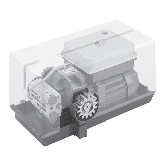
SUPER 3600
Scarica questo manuale sul tuo cellulare
Téléchargez ce manuel sur votre mobile
Download this manual on your mobile
Laden Sie dieses Handbuch auf Ihr Handy herunter
Descarga este manual en tu móvil
Operatore
Operateur
Operator
Torantrieb
Operador
SUPER 3600
SUPER 3600 ICE
Die korrekte Bedienung des Bedieners ist nur gewährleistet, wenn er von einem RIB-Bedienpanel verwaltet wird
ITALIANO pag. 05 / FRANÇAIS pag. 17 / ENGLISH page 29/ DEUTSCH pag. 41 / ESPAÑOL pag. 53
Alimentazione
Peso max cancello
Alimentation
Poids maxi portail
Power Supply
Max gate weight
Stromspannung
Max Torgewicht
Alimentacion
Peso máx verja
230V 50/60 Hz
3600 kg
Il corretto funzionamento dell'operatore è garantito solo se viene gestito da un quadro di comando RIB
Le bon fonctionnement de l'opérateur n'est garanti que s'il est géré par un panneau de contrôle RIB
The correct operation of the operator is guaranteed only if it is managed by a RIB control panel
El funcionamiento correcto del operador solo está garantizado si está gestionado por un panel de control RIB
con / avec / with / mit
L1/R2-CRX
Disegni tecnici per progetti
Dessins techniques pour les projets
Technical drawings for projects
Technische Zeichnungen für Projekte
Dibujos técnicos para proyectos.
Manuali online interattivi
Manuels interactifs en ligne
Interactive online manuals
Interaktive Online-Handbücher
Manuales interactivos en línea.
Spinta max
Coppia max
Poussée maxi
Couple maxi
Max Thrust
Max torque
Max Schubkraft
Max. Drehmoment
Max Empuje
Coppia max
4700/4150 N
200/175 Nm
Vedere pagina 15
Voir page 27
See page 39
Siehe Seite 51
Ver página 63
Codice
Code
Code
Code
Codigo
AA31020
AA31024
Publicité
Table des Matières

Manuels Connexes pour RIB SUPER 3600


Sommaire des Matières pour RIB SUPER 3600
- Page 1 Le bon fonctionnement de l’opérateur n’est garanti que s’il est géré par un panneau de contrôle RIB The correct operation of the operator is guaranteed only if it is managed by a RIB control panel Die korrekte Bedienung des Bedieners ist nur gewährleistet, wenn er von einem RIB-Bedienpanel verwaltet wird El funcionamiento correcto del operador solo está...
- Page 2 2° - En ce qui concerne la section et le type des câbles, RIB conseille d’utiliser un câble de 2° - Per la sezione ed il tipo dei cavi la RIB consiglia di utilizzare un cavo di tipo H05RN-F con type H05RN-F ayant une section minumum de 1,5 mm 2 et de toute façon, s’en tenir à...
- Page 4 L’eliminazione dei materiali va fatta rispettando le norme vigenti. Non gettate il vostro 2° - Para la sección y el tipo de los cables, RIB aconseja utilizar cables de tipo H05RN-F con apparecchio scartato, le pile o le batterie usate nei rifiuti domestici. Avete la responsabilità di sección mínima de 1,5 mm 2 e igualmente atenerse a la norma IEC 364 y a las normas de...
-
Page 8: Collegamenti Elettrici
COLLEGAMENTI ELETTRICI L1 cod. AC08082 Manuali online interattivi Manuels interactifs en ligne Interactive online manuals Interaktive Online-Handbücher Manuales interactivos en línea. -
Page 17: Schéma Détaillé De L'installation
SCHÉMA DÉTAILLÉ DE L’INSTALLATION A - Operateur SUPER 3600 B - Photocellules p/protec. externe C - Cremaillere m6 D - Selecteur E - Antenne radio F - Signal electrique H - Poteau zingué p/cellule ne I - Photocellules p/protection interne L - Barre palpeuse mécanique fixé... -
Page 18: Contrôle Pré-Installation
INSTALLATION SUPER 3600 CONTRÔLE PRÉ-INSTALLATION !! LE PORTAIL DOIT SE DÉPLACER SANS FROTTER !! N.B.: Il est impératif d’uniformiser les caractéristiques du portail avec les normes et les lois en vigueur. La porte peut être automatisée seulement si elle est en bon état et qu’elle est conforme à... -
Page 19: Installation Du Motor E De La Cremaillere
INSTALLATION DU MOTOR E DE LA CREMAILLERE La crémaillère doit être fixée à une certaine hauteur par rapport à la base du moteur. Cette hauteur peut être modifiée grâce à des boutonnières qui sont présentes sur la crémaillère. Le réglage en hauteur est effectué afin que le portail ne s’appuie pas sur l’engrenage de traction du réducteur (Fig. -
Page 20: Branchements Électriques
BRANCHEMENTS ÉLECTRIQUES L1 code AC08082 Manuali online interattivi Manuels interactifs en ligne Interactive online manuals Interaktive Online-Handbücher Manuales interactivos en línea. - Page 21 A - BRANCHEMENTS PROG IL EST OBLIGATOIRE DE INSTAURER LA FICHE AVEC DIP 13 EN POSITION “ON”. POWER 230 VAC MOTOR CAPACITOR L1 - N Alimentation 230 Vca 50/60 Hz (120 V 60 Hz sur demande) PROBE PAS DISPONIBLE Clignotant (max 40 W) ENCODER PAS DISPONIBLE Connexion commun du moteur...
- Page 22 B - RÉGLAGES DL14 Encodeur active (rosso) DL15 Commande PROG et RADIO sur molex (vert) DIP 1 CONTRÔLE D’ENTRETIEN (PAGE 25) (ON) B.I.O. Commande de horloge (vert) DIP 2 PROGRAMMATION DE LA DURÉE (ON) (POINT C) PED. Commande ouverture piétonne (vert) DIP 2-1 PROGRAMMATION DES LAPS DE TEMPS D’OUVERTURE POUR PIÉTONS (DIP 2 ON suivi de START Commande impulsif...
-
Page 23: Fonctionnement Des Accessoires De Commande
S’il est actionné à portail ouvert piéton, il Grâce à l’application RIB GATE, il est possible de configurer le fonctionnement de ce relais à le ferme. Si actionné pendant la fermeture, il rouvre le portail. -
Page 24: Signalisations Visuelles Et Acoustiques
(avec reprise du mouvement inverse après une seconde même si ces dernières demeurent occupées). FONCTION PRÉ-CLIGNOTEMENT DIP 5 OFF => Le moteur, le clignotant et le ronfleur partent simultanément. ATTENTION: Si la led du récepteur reste allumée, il est possible qu’ il y ait des perturbations DIP 5 ON =>... - Page 25 Si les leds ne s’allument pas, en maintenant toujours le portail en position intermédiaire, vérifier les points ci-après et éventuellement remplacer les composants qui ne fonctionnent pas. éteinte Bouton de STOP en panne (Dans le cas où le STOP n’est pas connecté, ponter entre COM A+ et STOP).
-
Page 26: Signalisations Pendant Le Fonctionnement
TABLEAU RÉCAPITULATIF ALARMES VISUELLES ET SONORES SIGNALISATIONS EN COURS DE PROGRAMMATION ÉVÉNEMENT ÉTAT BUZZER ÉTAT CLIGNOTEUR ÉTAT LED DL1 DIP 1 ON (mode homme mort) Éteint Éteint Clignote 250 ms ON/OFF Ou panne d'une sécurité DIP 2 ON (programmation course totale) Éteint Éteint Clignote 500 ms ON/OFF... -
Page 27: Emetteur Radio Sun
MODULE RADIO 433MHz EMETTEUR RADIO SUN cod. ACG8069 SUN 2CH cod. ACG6052 SUN 4CH cod. ACG6054 SUN CLONE 2CH cod. ACG6056 SUN CLONE 4CH cod. ACG6058 SUN-PRO 2CH cod. ACG6210 SUN-PRO 4CH cod. ACG6214 APP8054 Carte APP+ APP8050 Carte APP pour gérer le tableau de contrôle via pour gérer le tableau de contrôle via Bluetooth 4.2... -
Page 28: Transmetteur Radio Red
RED permet la réalisation d’une installation avec barres palpeuses fixées également sur le battant en mouvement sans l’adoption de systèmes d’assemblage de câbles. Il est conforme à la norme EN13849-1:2007 et associé à un tableau électronique RIB, il est un dispositif de protection de Classe 2. - Page 66 COLLEGAMENTI FOTOCELLULE - CONNEXIONS PHOTOCELLULE - PHOTOCELLS CONNECTIONS FOTOZELLEN VERBINDUNGEN - CONEXIONES FOTOCÉLULAS 4 fotocellule NOVA sincronizzate con autotest 4 photocellules NOVA synchronisées avec autotest 4 NOVA photocells synchronized with self-test 4 NOVA Photozellen synchronisiert mit Selbstkontrolle 4 fotocélulas NOVA sincronizadas con autotest PHOT1 PHOT2 A+ TEST COM A+...
- Page 68 R.I.B. S.r.l. - Via Matteotti, 162 - 25014 Castenedolo - Brescia - Italy Tel. ++39.030.2135811 - www.ribind.it - ribind@ribind.it Apparecchio modello : Oggetto della dichiarazione : SUPER 3600 Modèle d'appareil : Objet de la déclaration : Apparatus model : Object of the declaration :...