Publicité
Liens rapides
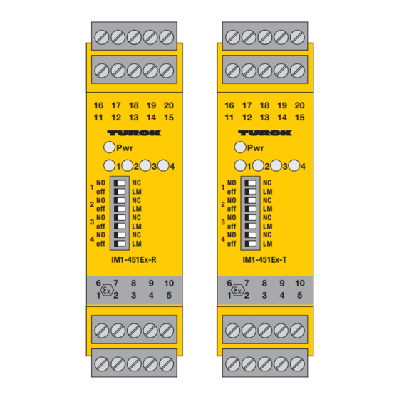
Trennschaltverstärker
IM1-451Ex-R/IM1-451Ex-T
IM1-451-R/IM1-451-T
Gerätekurzbeschreibung
• • • • •
Galvanisch getrennte Übertragung
von binären Schaltzuständen
• • • • •
Eigensichere Eingangskreise
(nur IM1-451Ex-...),
siehe Hinweise auf den Seiten 5 + 6
• • • • •
Anschluss von Sensoren nach
EN 60947-5-6 (NAMUR) (I) oder
mechanischen Schaltern (II + III),
siehe Fig. 2 + 4
• • • • •
Zuschaltbare Eingangskreisüber-
wachung auf Drahtbruch und
Kurzschluss
• • • • •
Einstellbare Wirkungsrichtung der
Ausgangskreise (Funktionstabelle
siehe unten)
Mechanische Kontakte
å
Beim Einsatz von mechanischen
Kontakten und aktivierter Eingangs-
kreisüberwachung muss in unmittel-
barer Nähe zum Kontakt das
anschlussfertige Widerstandsmodul
vom Typ WM1 (Ident-Nr.: 0912101)
oder eine Widerstandsbeschaltung,
wie in der Funktionstabelle angege-
ben, verwendet werden.
Funktionstabelle
Aufgeführt sind die verschiedenen Eingangs-
zustände mit den entsprechenden Aus-
gangszuständen. Zu beachten ist, dass
das Schaltverhalten von induktiven Sen-
soren nach EN 60947-5-6 (NAMUR) dem
von mechanischen Öffner-Kontakten ent-
spricht. Das Schaltverhalten von kapazi-
tiven und magnet-induktiven Sensoren
entspricht dem von Schließer-Kontakten.
Eingang/input/circuit de commande
Induktiver Sensor
inductive sensor
Wirkungsrichtung
détecteur inductif
Function mode
EN 60947-5-6
Sens d'action
NAMUR
Arbeitsstromverhalten
load current mode (N.O.)
fonction travail
N.O.
Ruhestromverhalten
no load current mode (N.C.)
fonction repos
N.C.
Switching Amplifier
IM1-451Ex-R/IM1-451Ex-T
IM1-451-R/IM1-451-T
Short description
• • • • •
Galvanically isolated transmission of
binary switching states
• • • • •
Intrinsically safe input circuits
(only IM1-451Ex-...),
see information on pages 5 + 6
• • • • •
Connection of sensors per
EN 60947-5-6 (NAMUR) (I) or
mechanical contacts (II + III),
see Fig. 2 + 4
• • • • •
Selectable input circuit monitoring for
wire-break and short-circuit
• • • • •
Adjustable output function mode (see
function truth table below)
Mechanical contacts
å
When using mechanical contacts
and activating the input circuit
monitoring function, it is required to
connect the ready-made resistor
module type WM1 (ident-no:
0912101) in direct proximity to the
contact, or to implement a resistor
circuitry as shown in the function
table.
Function table
The function table lists the various input
states together with the according output
states. Please note that the switching
performance of inductive sensors per
EN 60947-5-6 (NAMUR) accords to that
of normally-closed mechanical contacts.
The switching performance of capacitive
and magnet-inductive sensors accords to
that of normally-open contacts.
Ausgang/output/sortie
mechanischer Kontakt
kein Fehler/normal/sans défaut
dry contact
Schaltausgang
contact mécanique
switching output
R1 = 1...2,2 kW (>
/
W)
1
4
sortie de commutation
R2 = 10...22 kW (>
/
W)
1
4
R1
0
R2
R1
1
R2
R1
1
R2
R1
0
R2
Amplificateur séparateur
IM1-451Ex-R/IM1-451Ex-T
IM1-451-R/IM1-451-T
Brève description de l'appareil
• • • • •
Transmission d'états de commutation
binaires séparés galvaniquement
• • • • •
Circuits d'entrée à sécurité intrinsèque
(seulement IM1-451Ex-...),
voir instructions aux pages 5 + 6
• • • • •
Raccordement de détecteurs suivant
EN 60947-5-6 (NAMUR) (I) ou de
contacts mécaniques (II + III),
voir Fig. 2 + 4
• • • • •
Surveillance du circuit d'entrée aux
ruptures de câble et aux courts-circuits
désactivable
• • • • •
Fonction des circuits de sortie
ajustable (voir tableau ci-dessous)
Contacts mécaniques
å
En cas d'utilisation de contacts
mécaniques et d'une surveillance du
circuit d'entrée activée, le module de
résistance en ordre de marche (type
WM1, no. d'identité 0912101) ou
les résistances, comme proposées
dans le tableau fonctionnel, doivent
être montés directement sur le
contact.
Tableau de fonction
Il indique les différents états d'entrée et
les états de sortie correspondants. Il est
à noter que le comportement de commu-
tation des détecteurs inductifs suivant
EN 60947-5-6 (NAMUR) correspond à
celui des contacts mécaniques à ouverture
et que celui des détecteurs capacitifs et
magnéto-inductifs correspond à celui des
contacts mécaniques à fermeture.
mit Fehler/short or wire-break/avec défaut
Störmeldeausgang
Schaltausgang
alarm output
switching output
sortie de sig. de défaut
sortie de commutation
1
0
1
0
1
0
0
1
Störmeldeausgang
alarm output
sortie de sig. de défaut
0
0
0
0
Publicité

Manuels Connexes pour turck IM1-451Ex-R


Sommaire des Matières pour turck IM1-451Ex-R
- Page 1 Trennschaltverstärker Switching Amplifier Amplificateur séparateur IM1-451Ex-R/IM1-451Ex-T IM1-451Ex-R/IM1-451Ex-T IM1-451Ex-R/IM1-451Ex-T IM1-451-R/IM1-451-T IM1-451-R/IM1-451-T IM1-451-R/IM1-451-T Gerätekurzbeschreibung Short description Brève description de l’appareil • • • • • Galvanisch getrennte Übertragung • • • • • Galvanically isolated transmission of • • • • •...
- Page 2 Klemmenbelegung (Fig. 2 + 4) Terminal configuration (Fig. 2 + 4) Raccordement des bornes (Fig. 2 + 4) Eingangskreise: Input circuits: Circuits d’entrée: IM1-451Ex-R/IM1-451Ex-T IM1-451Ex-R/IM1-451Ex-T IM1-451Ex-R/IM1-451Ex-T 1, 2 eigensicherer Eingangskreis 1, 2 intrinsically safe input circuit 1, 2 circuit d'entrée à...
- Page 3 £ 2 A NAMUR £ 500 VA £ 60W – YE/RD YE/RD – YE/RD NAMUR – YE/RD – – NAMUR IM1-451Ex-R IM1-451Ex-T Power Power IM1-451Ex-R IM1-451Ex-T Fig. 3 Fig. 4 16 17 16 17 – – 11 12 11 12 YE/RD...
- Page 4 IM1-451...-R/IM1-451...-T Einstellungen (Fig. 1 + 3) Adjustments (Fig. 1 + 3) Réglages (Fig. 1 + 3) Über die frontseitigen Schalter lassen sich The front panel switches serve to select Les commutateurs en face avant permet- für jeden Kanal die Wirkungsrichtung und the output function and input circuit tent de programmer le mode d’action et die Eingangskreisüberwachung separat...
- Page 5 Alle Les données essentielles de l‘attestation d‘examen gültigen nationalen und internationalen Bescheini- CE figurent au verso. L‘ensemble des certificats gungen der TURCK-Geräte finden Sie im Internet nationaux et internationaux des appareils TURCK (www.turck.com). peuvent être obtenus par internet (www.turck.com).
- Page 6 II (1) G D [EEx ia] IIC Irrtümer und Änderungen vorbehalten / Subject to change without notice / Sous réserve de modifications • © Hans Turck GmbH & Co. KG 2005 Hans Turck GmbH & Co. KG • D–45466 Mülheim/Ruhr • Tel. 0208/4952-0 • Fax 0208/4952-264 • E-Mail: turckmh@turck.com • Internet: www.turck.com...