Hydac HDA 5500 Notice D'utilisation
Masquer les pouces
Voir aussi pour HDA 5500:
- Notice d'utilisation (55 pages) ,
- Notice d'utilisation (76 pages)
Table des Matières
Publicité
Les langues disponibles
Les langues disponibles
Liens rapides
Digitales Anzeigegerät HDA 5500
für Ölzustandssensor HYDACLab
und Contamination Sensor CS1000
Digital Display Unit HDA 5500
for Oil Condition Sensor HYDACLab
and Contamination Sensor CS1000
Afficheur digital HDA 5500 pour capteur
d'état de l'huile HYDACLab
et de pollution CS1000
Benutzerhandbuch
User Manual
Notice d'utilisation
HDA 5500-0-2-AC-006 (CM1k)
HDA 5500-0-2-DC-006 (CM1k)
Stand:
25.06.2008
Mat..-Nr.
669731
®
HLB 1000
®
®
HLB1000
HLB1000
Publicité
Chapitres
Table des Matières

Manuels Connexes pour Hydac HDA 5500

Sommaire des Matières pour Hydac HDA 5500
- Page 1 HLB 1000 und Contamination Sensor CS1000 Digital Display Unit HDA 5500 ® for Oil Condition Sensor HYDACLab HLB1000 and Contamination Sensor CS1000 Afficheur digital HDA 5500 pour capteur ® d’état de l'huile HYDACLab HLB1000 et de pollution CS1000 Benutzerhandbuch User Manual...
- Page 2 HDA 5500 für HLB1000 und CS1000...
-
Page 3: Table Des Matières
7 Programmierung Einstellung der Grundeinstellungen Übersicht Menü der Grundeinstellungen 8 Anschluss des Ölzustandssensor HLB 1000 HDA 5500 und Ölzustandssensor HLB 1000 HDA 5500 und Contamination Sensor CS 1000 9 Digitalanzeige Standardanzeige Sonderanzeige Sequentieller Analogausgang des HLB 1000 Sequentieller Analogausgang des CS 1000 10 Ausgangsverhalten 10.1... -
Page 4: Einleitung
• Alle einschlägigen und allgemein anerkannten sicherheitstechnischen Bestimmungen sind einzuhalten. 3 Funktionen Das HDA 5500 für Condition Monitoring Sensoren ist speziell für die Verwendung mit dem Ölzustandssensor HLB 1000 oder dem Contamination Sensor CS ausgelegt; es bietet folgende Funktionen: • Anzeige eines Maximal- oder Minimalwertes (Schleppzeigerfunktion) •... -
Page 5: Bedienelemente
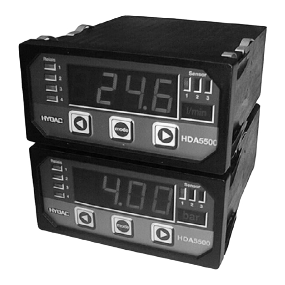
HDA 5500 für HLB1000 und CS1000 4 Bedienelemente 4-stellige Digitalanzeige LED-Anzeigen aktiver LED-Anzeigen Schaltpunkte aktiver Sensor Sensor Relais 1 2 3 HDA5500 MODE MODE Anzeige der Einheit von Sensor 1, 2, 3 oder 4 Tasten zur Einstellung der Schaltpunkte, Rückschaltpunkte und der Menüfunktionen... -
Page 6: Montage Und Inbetriebnahme
HDA 5500 für HLB1000 und CS1000 6 Montage und Inbetriebnahme 6.1 Mechanischer Einbau Das HDA 5500 ist ein Schalttafeleinbaugerät mit einem Normeinbaugehäuse 96 x 48 mm und benötigt einen Schalttafelausschnitt von 92 x 45 mm. Schalttafeldicke: mindestens 1,25 mm Einbautiefe: mindestens 150 mm Panel-Clips Spannführungen... -
Page 7: Versorgungsspannung
2 s wird der eigentliche Wert angezeigt. Achtung: Bevor Sensoren angeschlossen werden, sollte das HDA 5500 passend eingestellt werden. Wenn kein Eingangssignal anliegt oder während der Referenzphase (bis zu 2 Minuten), dann wird je nach Signalart folgendes angezeigt: •... -
Page 8: Programmierung
HDA 5500 für HLB1000 und CS1000 7 Programmierung Zur Anpassung an die jeweilige Applikation wird das HDA 5500 mittels Variation der Grund- einstellungen programmiert. Die Grundeinstellungen sind in einem Menü zusammengefasst. Achtung: Bei aktiviertem Menü werden keine Schaltfunktionen ausgeführt. 7.1 Einstellung der Grundeinstellungen Um die Grundeinstellungen zu ändern, ist das Menü... -
Page 9: Übersicht Menü Der Grundeinstellungen
HDA 5500 für HLB1000 und CS1000 7.2 Übersicht Menü der Grundeinstellungen Menüpunkt Einstellung Einstellbereich Voreinstellung Device: HLB, Geräte auswahl zur Messwertanzeige des angeschlossenen HLB 1000 Geräte auswahl zur Messwertanzeige des angeschlossenen CS 1000 Bei Geräteauswahl HLB 1000 Zuordnung Schaltausgang 1 (S.S.1) r.ViS. - Page 10 HDA 5500 für HLB1000 und CS1000 Menüpunkt Einstellung Einstellbereich Voreinstellung Schaltfunktion Schaltausgang 3 (S.S.3) r.ViS. r.ViS. r.diE. Analog zu Schaltausgang 1 (s. o.), d. h. im weiteren: r.HuM. • Schaltfunktion (S.M.3) TEMP. • Schaltrichtung (S.d.3) • Einschaltverzögerung (T.on.3) • Abschaltverzögerung (T.oF.3) 0..99.99 s...
- Page 11 HDA 5500 für HLB1000 und CS1000 Menüpunkt Einstellung Einstellbereich Voreinstellung Dezimalstelle für Anzeige der rel. Viskositätsänderung (dEc.V.) 0 .. 0.000 Dezimalstelle/n des angezeigten Messwertes der rel. Viskositätsänderung Unterer Grenzwert der rel. Viskositätsänderung (LOr.V.) -999..9899 -30.0 Unterer Grenzwert des Anzeigebereichs der rel. Viskositätsänderung Oberer Grenzwert der rel.
- Page 12 HDA 5500 für HLB1000 und CS1000 Menüpunkt Einstellung Einstellbereich Voreinstellung Dezimalstelle für Anzeige der Temperatur (dEc.T.) 0 .. 0.000 Dezimalstelle/n des angezeigten Messwertes der Temperatur Unterer Grenzwert der Temperatur (LOr.T.) -999..9899 -25.0 Unterer Grenzwert des Anzeigebereichs der Temperatur Oberer Grenzwert der Temperatur (Hir.T.) -899..9999...
- Page 13 Die Voreinstellungen der unteren und oberen Grenzwerte von Kanal 1 bis 4 (LO.1 bis LO.4 und Hi.1 bis HI.4) entsprechen den Werten bei Betrieb des HLB 1000 am HDA 5500. Bei Betrieb des CS1000 am HDA5500 ist zu beachten: Für die im CS 1000 eingestellten analogen Signalausgangsformen HDA.ISO, HDA.SAE oder HDA.NAS müssen die Vorein-...
- Page 14 HDA 5500 für HLB1000 und CS1000 Menüpunkt Einstellung Einstellbereich Voreinstellung Schaltfunktion Schaltausgang 2 (S.S.2) Kanal 1 Kanal 1 Kanal 2 Analog zu Schaltausgang 1 (s. o.), d. h. im weiteren: Kanal 3 • Schaltfunktion (S.M.2) Kanal 4 • Schaltrichtung (S.d.2) •...
- Page 15 HDA 5500 für HLB1000 und CS1000 Menüpunkt Einstellung Einstellbereich Voreinstellung Primäranzeige (PriM) Wert, der permanent im Display angezeigt wird: Kanal 1 Kanal 1 Kanal 2 Messwert von Kanal 1 Kanal 3 Kanal 4 Minimalwert von Kanal 1 Spitzenwert von Kanal 1...
- Page 16 HDA 5500 für HLB1000 und CS1000 Menüpunkt Einstellung Einstellbereich Voreinstellung Hintergrundbeleuchtung der Einheit von Kanal 1(uni.1.) Hintergrundbeleuchtung ein Hintergrundbeleuchtung aus Dezimalstelle für Anzeige von Kanal 2 (dEc.2.) 0 .. 0.000 Dezimalstelle/n des angezeigten Messwertes von Kanal 2 Unterer Grenzwert von Kanal 2 (LO.2.) -999..9899...
- Page 17 HDA 5500 für HLB1000 und CS1000 Menüpunkt Einstellung Einstellbereich Voreinstellung Zuordnung des Analogausgangs zu Signal (ouT.S) Kanal 1 Kanal 1 Kanal 2 Kanal 3 der Analogausgang gibt das Signal Kanal 4 von Kanal 1 aus der Analogausgang gibt das Signal...
-
Page 18: Anschluss Des Ölzustandssensor Hlb 1000
HDA 5500 für HLB1000 und CS1000 8 Anschluss des Ölzustandssensor HLB 1000 8.1 HDA 5500 und Ölzustandssensor HLB 1000 HDA 5500-0-2-AC-006 (CM1k) X2.6 +12 V Signal 1 HLB 1000 X2.5 AGND X2.7 Signal 2 HDA 5500-0-2-DC-006 (CM1k) X1(+) 12..32VDC 12..32V... -
Page 19: Digitalanzeige
2 Minuten dauern; erst nach Abschluss der Initialisierung sind die angezeigten Messwerte aussagekräftig. • Übersteigt der Messwert den oberen Anzeigebereich des HDA 5500, so wird der Mess- wert nicht mehr angezeigt. Der obere Anzeigebereich blinkt. • Liegt der Messwert unterhalb von 1 % des unteren Anzeigebereichs, so wird der Mess- wert nicht mehr angezeigt. -
Page 20: Sequentieller Analogausgang Des Hlb 1000
HDA 5500 für HLB1000 und CS1000 9.3 Sequentieller Analogausgang des HLB 1000 Das Analogausgangssignal der Messwerte wird wie folgt sequentiell an PIN 4 des HLB 1000 an das HDA 5500 ausgegeben. Start Start Rel. Rel. 20mA Visko Feuchte Rel. Status Temp. -
Page 21: Sequentieller Analogausgang Des Cs1000
HDA 5500 für HLB1000 und CS1000 9.4 Sequentieller Analogausgang des CS1000 Das Analogausgangssignal der Messwerte wird wie folgt sequentiell an PIN 2 des CS1000 an das HDA 5500 ausgegeben. Start Start 20mA 4µm 14µm 6µm Status 21µm Erläuterung: Ausgabe sequentieller Analogausgang: (jeweils 4..20 mA) -
Page 22: Ausgangsverhalten
HDA 5500 für HLB1000 und CS1000 10 Ausgangsverhalten Das HDA 5500 verfügt über einen Analogausgang, dessen Signal proportional zu einem Eingangssignal ist. Der Analogausgang kann jedem der Signale (rel. Viskositätsänderung, rel. Dielektrizitätszahländerung, rel. Feuchte, Temperatur bei Geräteauswahl HLB1000 sowie CH1, CH2, CH3 oder CH4 bei Geräteauswahl CS1000) zugeordnet werden. -
Page 23: Schaltausgänge
HDA 5500 für HLB1000 und CS1000 10.2 Schaltausgänge Jeder Schaltausgang besteht aus einem Relais, dessen Schaltkontakte als Öffner oder Schließer angeschlossen werden können. Für jeden Schaltausgang können während des regulären Betriebs die folgenden Parameter eingestellt werden (siehe Kap. 7.2, Übersicht Menü... -
Page 24: Anschluss Von Bis Zu Vier Schaltausgängen
HDA 5500 für HLB1000 und CS1000 Beispiel für Schaltausgang 1 (Relais aktiviert): Messgröße Hi.1 plus 1% FS Rückschaltwert Sicherheitszone Schaltwert hi.1 Lo.1 Schaltwert Sicherheitszone Lo.1 minus 1% FS Rückschaltwert Abkürzungen: "HI 1" bis "HI 4" = High level 1 bis 4 = oberer Schaltpunkt 1 bis 4 "Lo 1"bis "Lo 4"... -
Page 25: Einstellen Von Schaltpunkten Und Hysteresen
Wenn mode länger als ca. 5 s festgehalten wird, dann wird das Menü der Grundeinstellun- gen aktiviert. 11.1 Schaltausgänge Vorgehensweise bei HDA 5500 mit Schaltausgang eingestellt zu Schaltpunkt und Hysterese: • Während des regulären Betriebs die Taste mode betätigen. Dabei wird SP (Schaltpunkt) angezeigt. -
Page 26: Programmierfreigaben
3 s nicht betätigt werden, dann wird die angezeigte Einstellung übernommen. Wurde eine Einstellung geändert, so wird dann für ca. 2 s ProG (Programmierung) angezeigt. Damit ist die geänderte Einstellung im HDA 5500 ge- speichert. Anschließend wechselt die Anzeige zum regulären Betrieb. -
Page 27: Änderung Der Hauptprogrammierfreigabe
12.2 Ändern der Hauptprogrammierfreigabe Ein Ändern der Hauptprogrammierfreigabe kann nur beim Einschalten des HDA 5500 vorgenommen werden. Wenn das HDA 5500 bereits in Betrieb ist, dann ist zuerst die Ver- sorgungsspannung abzuschalten oder das HDA 5500 von der Versorgungsspannung zu trennen. -
Page 28: Technische Daten
HDA 5500 für HLB1000 und CS1000 13 Technische Daten Anzeigebereich Anzeige 4-stellige 7-Segment LED-Anzeigefeld, rot, Zeichenhöhe 14,2 mm 3 LED für aktiven Sensor, 4 LED für Schaltpunkte Anzeigebereich - 999 .. 9999 (frei einstellbar) Anzeigeeinheiten mit Hintergrund Beleuchtung °C,°F, % (gewünschte Einheit aus Folie ausschneiden und in seitliche Einschublasche schieben) Eingangsgrößen... -
Page 29: Typenschlüssel Hda 5500
HDA 5500 für HLB1000 und CS1000 14 Typenschlüssel HDA 5500 Bestellangaben 5 5 0 0 – 0 – 2 – X X – 0 0 6 Eingänge 0 = Ein Analogeingang Ausgänge 2 = Vier Relaisausgänge Versorgungsspannung AC = 85..265 VAC DC = 12..32 VDC... -
Page 30: Geräteabmessungen
HDA 5500 für HLB1000 und CS1000 15 Geräteabmessungen - 29 -... -
Page 31: Pinbelegung
GERÄT BESCHREIBUNG Variante HDA 5500 – X – X – AC – 000 ~ / ~ Versorgungsspannungseingänge 85VAC bis 265VAC 50/60Hz Wechselstrom 1 , 2 und 3 HDA 5500 – X – X – DC – 000 + / - Versorgungsspannungseingänge 24VDC Gleichstrom... -
Page 32: Fehlermeldungen
HDA 5500 für HLB1000 und CS1000 17 Fehlermeldungen Wird ein Fehler erkannt, so erscheint eine entsprechende Fehlermeldung. Diese muss mit einem beliebigen Tastendruck bestätigt werden. Mögliche Fehlermeldungen sind: Er.01 Die Schaltpunkte und Hysteresen wurden so eingestellt, dass der resultierende Rückschaltpunkt außerhalb des erlaubten Einstellbereiches liegt. - Page 33 HDA 5500 for HLB 1000 and CS 1000 CONTENTS 1 Introduction European standards compatibility 2 Safety instructions 3 Functions 4 Operating keys 5 Selecting and displaying the unit of measurement 6 Installation and commissioning Mechanical installation Electrical connection Supply voltage...
-
Page 34: Introduction
• The HDA 5500 must not be put into service if any known defects, either electrical or mechanical, are apparent. • The unit must be installed exactly according to the instructions. -
Page 35: Operating Keys
HDA 5500 for HLB 1000 and CS 1000 4 Operating keys 4-digit digital display LED display of active LED display switching points of active sensor Sensor Relais 1 2 3 HDA5500 MODE MODE Display of unit of measurement sensor 1, 2, 3 or 4... -
Page 36: Installation And Commissioning
HDA 5500 for HLB 1000 and CS 1000 6 Installation and commissioning 6.1 Mechanical installation The HDA 5500 is a control panel unit with a standard mounting housing 96 x 48 mm and requires a control panel cut-out: 92 x 45 mm •... -
Page 37: Supply Voltage
Important: Before sensors are connected, the HDA 5500 must be set appropriately. If there is no input signal, or during the reference phase (up to 2 minutes), then, depending on the type of signal, the following will be displayed: •... -
Page 38: Programming
HDA 5500 for HLB 1000 and CS 1000 7 Programming In order to adapt the unit to a particular application, the HDA 5500 is programmed by varying the basic settings. The basic settings are combined in a menu. Important: When the menu is activated, no switching functions are carried out. -
Page 39: Overview Of Basic Settings Menu
HDA 5500 for HLB 1000 and CS 1000 7.2 Overview of basic settings menu Menu point Setting Setting range Default setting Device: HLB, Device selected to display the values measured by the HLB 1000 connected Device selected to display the values measured... - Page 40 HDA 5500 for HLB 1000 and CS 1000 Menu point Setting Setting range Default setting Switching function switching output 3 (S.S.3) r.ViS. r.ViS. r.diE. Similar to switching output 1 (see above), and likewise for: r.HuM. • Switching mode (S.M.3) TEMP.
- Page 41 HDA 5500 for HLB 1000 and CS 1000 Menu point Setting Setting range Default setting Decimal place for display of rel. change in viscosity (dEc.V.) 0 .. 0.000 Decimal place(s) when displaying measured values of rel. change in viscosity Lower display range of rel. change in viscosity (LOr.V.) -999..9899...
- Page 42 HDA 5500 for HLB 1000 and CS 1000 Menu point Setting Setting range Default setting Decimal place for display of temperature (dEc.T.) 0 .. 0.000 Decimal place(s) when displaying measured values of temperature Lower display range of temperature (LOr.T.) -999..9899 -25.0...
- Page 43 The default settings of the upper and lower limits of channels 1 to 4 (LO.1 to LO.4 and Hi.1 to HI.4) correspond to the values for operating the HLB 1000 on the HDA 5500. When operating the CS1000 on the HDA5500 please note that: The default setting ranges pre-set in the CS 1000 for the analogue signal output forms HDA.ISO, HDA.SAE or...
- Page 44 HDA 5500 for HLB 1000 and CS 1000 Menu point Setting Setting range Default setting Allocation of switching output 2 (S.S.2) Channel 1 Channel 1 Channel 2 Similar to switching output 1 (see above), and likewise for: Channel 3 •...
- Page 45 HDA 5500 for HLB 1000 and CS 1000 Menu point Setting Setting range Default setting Primary display (PriM) Value which is normally displayed: Channel 1 Channel 1 Channel 2 Measured value Channel 1 Channel 3 Channel 4 Lowest value Channel 1...
- Page 46 HDA 5500 for HLB 1000 and CS 1000 Menu point Setting Setting range Default setting Lower display range of channel 1 (LO.1.) -999..9899 -30.0 Lower limit of display range of channel 1 Upper display range of the channel (Hi.1.) -899..9999 30.0...
- Page 47 HDA 5500 for HLB 1000 and CS 1000 Menu point Setting Setting range Default setting Upper display range of temperature (Hi.4.) -899..9999 100.0 Upper limit of the display range of channel 4 Background lighting for the unit label for Channel 4(uni.4.)
-
Page 48: Hda 5500 And Oil Condition Sensor Hlb 1000
9..36V DC X2.5 CS1000 AGND AGND X2.7 Analog OUT Important: In order to operate the CS 1000 on the HDA 5500 the CS 1000 sensor must first be converted to the output signal HDA.ISO, HDA.SAE or HDA.NAS. - 17 -... -
Page 49: Digital Display
Initialisation of the HYDACLab ® can take up to 2 minutes; only once the initialisation has been completed are the measured values meaningful. • If the measured value exceeds the upper display range of the HDA 5500, then the measured value can no longer be displayed. The upper display range flashes. •... -
Page 50: Sequential Analogue Output Of The Hlb 1000
HDA 5500 for HLB 1000 and CS 1000 9.3 Sequential analogue output of the HLB 1000 The analogue output signal of the measured values is output at PIN 4 of the HLB 1000 to the HDA 5500 sequentially, as follows: Rel. -
Page 51: Sequential Analogue Output Of The Cs 1000
HDA 5500 for HLB 1000 and CS 1000 9.4 Sequential analogue output of the CS 1000 The analogue output signal of the measured values is output to PIN 2 of the CS 1000 to the HDA 5500 sequentially as follows. Start Start 20mA 4µm... -
Page 52: Output Response
HDA 5500 for HLB 1000 and CS 1000 10 Output response The HDA 5500 has an analogue output which is proportional to an input signal. The analogue output can be allocated to each of the signals (rel. change in viscosity, rel. change in dielectric constant, rel. -
Page 53: Switching Outputs
HDA 5500 for HLB 1000 and CS 1000 10.2 Switching outputs Each switching output consists of a relay, the switching contacts of which can be connected as N/C or N/O. For each switching output, the following parameters can be set during normal operation (see Point 7.2 Overview of the Basic Settings Menu):... -
Page 54: Connection Of Up To Four Switching Outputs
HDA 5500 for HLB 1000 and CS 1000 Example for switching output 1 (relay activated): Measured variable Switch-back value hi.1 plus 1% FS Safety Zone Switching value hi.1 Lo.1 Switching value Safety Zone Switch-back value Lo.1 minus 1% FS Abbreviations: "HI 1" to "HI 4" = High level 1 to 4 = upper switch point 1 or 4 "Lo 1"... -
Page 55: Adjusting Switch Points And Hystereses
If the mode key is pressed for longer than approximately 5 s, then the Basic Settings Menu will be activated! 11.1 Switching outputs Procedure for HDA 5500 with switching output set to switch point and hysteresis mode: • During normal operation, press the mode key. SP (switch point) is then displayed. -
Page 56: Programming Enable
3 s or longer, then the displayed setting is accepted. If a setting has been altered, then ProG (programming) is displayed for approximately 2 s. This means the changed setting is stored in the HDA 5500. Afterwards the display returns to normal operation. -
Page 57: Altering The Main Programming Enable
The main programming enable can only be altered when switching on the HDA 5500. If the HDA 5500 is already in operation, then the supply voltage must first be switched off or the HDA 5500 must be disconnected from the supply voltage. -
Page 58: Technical Specifications
HDA 5500 for HLB 1000 and CS 1000 13 Technical specifications Display range Display 4-digit 7-segment LED display, red, height of digits 14.2 mm 3 LEDs for active sensor 4 LEDs for switching relays Display range - 999..9999 (adjustable by user) Display units (of measurement) with background lighting °C,°F, %... -
Page 59: Model Code Hda 5500
HDA 5500 for HLB 1000 and CS 1000 14 Model code HDA 5500 Order details 5 5 0 0 – 0 – 2 – X X – 0 0 6 Inputs 0 = One analogue input Outputs 2 = Four relay outputs Supply voltage AC = 85..265 VAC... -
Page 60: Unit Dimensions
HDA 5500 for HLB 1000 and CS 1000 15 Unit dimensions Control panel thickness Control panel cut-out - 29 -... -
Page 61: Electrical Connections
UNIT DESCRIPTION Models HDA 5500 – X – X – AC – 000 ~ / ~ Supply voltage inputs 85VAC to 265VAC 50/60Hz 1 , 2 and 3 HDA 5500 – X – X – DC – 000 + / -... -
Page 62: Error Messages
HDA 5500 for HLB 1000 and CS 1000 17 Error messages If an error is detected, then a corresponding error message appears which must be acknowledged by pressing any key. Possible error messages are as follows: Er.01 The switching points and hystereses have been set in such a way that the resulting switch-back point is no longer within the permissible setting range. - Page 63 Réglages du menu de base Aperçu des réglages de base 8 Raccord du capeur de l'état de l'huile HLB 1000 HDA 5500 et capteur de l'état de l'huile HLB 1000 HDA 5500 et capteur de pollution CS 1000 9 Affichage digital Affichage standard Affichage spécial...
-
Page 64: Introduction
Afin d'éviter des risques inutiles ou des dégâts matériels ou humains suite à une mauvaise utilisation de l'appareil, merci de prendre connaissance des points suivants: • L'HDA 5500 ne doit être mis en service que s'il est dans un état technique et visuel irréprochable. -
Page 65: Eléments De Réglage
HDA 5500 pour HLB 1000 et CS 1000 4 Eléments de réglage Affichage des valeurs sur 4 digits LED indiquant la(es) sortie(s) LED indiquant active(s) l'entrée active Relais Sensor 1 2 3 HDA5500 MODE MODE Affichage de l'unité du capteur 1, 2, 3 ou 4 Touches pour le réglage... -
Page 66: Montage Et Mise En Service
HDA 5500 pour HLB 1000 et CS 1000 6 Montage et mise en service 6.1 Montage L'HDA 5500 est un appareil à encastrer en tableau avec un boîtier normalisé pour une découpe de 92 x 45 mm. • Dimension 92 x 45 mm •... -
Page 67: Tension D'alimentation
Attention: Avant de connecter un capteur, il faut que l'HDA 5500 soit configuré en conséquence. S'il n'y a pas de signal d'entrée ou lors de la phase de référence (jusqu'à 2 minutes), l'affichage suivant apparaît selon le type de signal: •... -
Page 68: Programmation
7 Programmation Pour s'adapter à chaque application, il est possible de modifier les paramètres de base de l'HDA 5500. Ces paramètres se trouvent dans le menu de base. Attention: Quand le menu de base est activé, les fonctions de commutations sont désactivées. -
Page 69: Aperçu Des Réglages De Base
HDA 5500 pour HLB 1000 et CS 1000 7.2 Aperçu des réglages de base Point du Plage de réglage Préréglage Réglage menu Raccordement du capteur HLB 1000 Raccordement du capteur CS 1000 Avec capteur HLB 1000 Affectation de la sortie de commutation 1 (S.S.1) r.ViS. - Page 70 HDA 5500 pour HLB 1000 et CS 1000 Point du Plage de réglage Préréglage Réglage menu Fonction de commutation de la sortie de commutation 3 r.ViS. r.ViS. (S.S.3) r.diE. r.HuM. Analogue à la sortie de commutation 1 (voir ci dessus), c.à d. au TEMP.
- Page 71 HDA 5500 pour HLB 1000 et CS 1000 Point du Plage de réglage Préréglage Réglage menu Reset time (r.TiM) 0 .. 3.600 s Durée d'affichage en seconds de la dernière valeur maximal / minimale atteinte Position de la virgule pour l'affichage de la modification de la viscosité...
- Page 72 HDA 5500 pour HLB 1000 et CS 1000 Point du Plage de réglage Préréglage Réglage menu Rétroéclairage de l'unité pour l'humidité rel. (uni.H.) Rétroéclairage allumé Rétroéclairage éteint Position de la virgule pour l'affichage de la température (dEc.T.) 0 .. 0.000 Nombre de décimales après la virgule pour la valeur de la...
- Page 73 (LO.1 à LO.4 et HI.1 à HI.4) correspondent par défaut aux valeurs du HBL 1000 sur le HDA 5500. A noter lors de la mise en service du CS 1000 sur le HDA 5500 : pour les types de signaux de sortie analogiques HDA.ISO, HDA.SAE ou HDA.NAS, les préréglages doivent être effectués de la manière suivante :...
- Page 74 HDA 5500 pour HLB 1000 et CS 1000 Point du Plage de réglage Préréglage Réglage menu Temporisation au déclenchement sortie de commutation 1 (T.oF1) 0..99.99 s Durée en secondes à laquelle chaque point de déclenchement doit être inférieure afin qu'une fonction de commutation soit exécutée.
- Page 75 HDA 5500 pour HLB 1000 et CS 1000 Point du Plage de réglage Préréglage Réglage menu Affichage primaire (PriM) Valeur affichée en permanence: Kanal 1 Kanal 1 Kanal 2 Valeur canal 1 Kanal 3 Kanal 4 Valeur min du canal 1...
- Page 76 HDA 5500 pour HLB 1000 et CS 1000 Point du Plage de réglage Préréglage Réglage menu Rétroéclairage de l’unité du canal 1(uni.1.) rétroéclairage allumé rétroéclairage éteint Position de la virgule pour l’affichage du canal 2(dEc.2.) 0 .. 0.000 Nombre de décimale après la virgule pour la valeur du canal 2 Valeur limite inférieur du canal 2(LO.2.)
- Page 77 HDA 5500 pour HLB 1000 et CS 1000 Point du Plage de réglage Préréglage Réglage menu Affectation de la sortie analogique (ouT.S) Kanal 1 Kanal 1 Kanal 2 Kanal 3 La sortie analogique restitue la mesure du canal 1 Kanal 4...
-
Page 78: Raccord Du Capeur De L'état De L'huile Hlb 1000
HDA 5500 pour HLB 1000 et CS 1000 8 Raccord du capeur de l'état de l'huile HLB 1000 8.1 HDA 5500 et capteur de l'état de l'huile HLB 1000 HDA 5500-0-2-AC-006 (CM1k) X2.6 +12 V Signal 1 HLB 1000 X2.5 AGND X2.7... -
Page 79: Affichage Digital
2 minutes. Les valeurs affichées ne sont probantes qu'à l'issue de l'initialisation. • Si la valeur excède la valeur de la plage d'affichage supérieure de l'HDA 5500, alors celle-ci ne s'affiche pas. La plage d'affichage supérieure clignote. •... -
Page 80: Sortie Analogique Séquentielle De L'hlb 1000
HDA 5500 pour HLB 1000 et CS 1000 9.3 Sortie analogique séquentielle de l'HLB 1000 Le signal analogique de la valeur de mesure est restitué comme suit, de manière séquentielle en PIN 4 de l'HLB 1000 vers l'HDA 5500: Démar- Démar-... -
Page 81: Sortie Analogique Séquentielle Du Cs 1000
HDA 5500 pour HLB 1000 et CS 1000 9.4 Sortie analogique séquentielle du CS 1000 Le signal analogique de la valeur de mesure est restitué comme suit, de manière séquentielle en PIN 2 du CS 1000 vers l'HDA 5500: Démar- Démar-... -
Page 82: Signaux De Sortie
HDA 5500 pour HLB 1000 et CS 1000 10 Signaux de sortie L'5500 dispose d'une sortie analogique dont le signal est proportionnel à un signal d'entrée. On peut affecter à la sortie analogique chacun des signaux (modification de l'humidité relative, modification de la constante diélectrique, humidité relative, température pour HLB 1000 ainsi que CH1, CH2, CH3, CH4 pour le CS 1000). -
Page 83: Sorties Relais
HDA 5500 pour HLB 1000 et CS 1000 10.2 Sorties relais Chaque sortie de commutation est associée à un relais, le point de contact de commutation peut être connecté ouvert ou fermé. Plusieurs paramètres peuvent êtres installés pour tous les points de contact de commutation lors de son fonctionnement régulier. (voir chapitre 7.2 Aperçu du menu des réglages de base):... -
Page 84: Valeur Mesurée
HDA 5500 pour HLB 1000 et CS 1000 Exemple pour la sortie de commutation 1 (relais activé): Valeur mesurée "0" hi.1 + 1% FS Recommutation Zone de sécurité Commutation hi.1 "1" Zone à surveiller "1" Commutation Lo.1 Zone de sécurité... -
Page 85: Réglage Des Seuils Et Hystérésis
Appuyer sur Relâcher mode réglages avec mode 11.2 Fenêtre de commutation Mode opératoire pour un HDA 5500 avec sortie de commutation paramétré sur fenêtre de commutation: • Lors du fonctionnement normal, appuyer sur la touche mode. Win (fenêtre de commutation) s'affiche Attention: Si la touche mode est maintenue pendant plus de 5 s, alors le menu des réglages de base est activé... -
Page 86: Remarques
12 Autorisations de programmation L'HDA 5500 dispose de 2 autorisations de programmation, l'autorisation de programmation de service et l'autorisation de programmation principale qui doivent toutes 2 être actives pour permettre de modifier les réglages. -
Page 87: Modification De L'autorisation De Programmation Principale
HDA 5500 pour HLB 1000 et CS 1000 12.2 Modification de l'autorisation de programmation principale La modification de l'autorisation de programmation principale n'est possible qu'à la mise sous tension de l'HDA 5500. En fonctionnement normal, il faut d'abord enlever l'alimentation de l'appareil. Mode opératoire: •... -
Page 88: Caractéristiques Techniques
HDA 5500 pour HLB 1000 et CS 1000 13 Caractéristiques techniques Etendue de mesure Afficheur 4 digits 7 segments led rouges 14.2 mm 3 leds pour les entrées 4 leds pour l'état des relais Plage de mesure -999..9999 (paramétrable) Unités disponibles avec rétro éclairage °C,°F, %... -
Page 89: Code De Commande Hda 5500
HDA 5500 pour HLB 1000 et CS 1000 14 Code de commande HDA 5500 Code de commande 5 5 0 0 – 0 – 2 – X X – 0 0 6 Entrées 0 = Une entrée analogique Sorties 2 = quatre sorties relais Tension d'alimentation AC = 85..265 VAC... -
Page 90: Dimensions
HDA 5500 pour HLB 1000 et CS 1000 15 Dimensions épaisseur paroi Découpe - 29 -... -
Page 91: Brochage
INDICATEUR DESCRIPTIF Variante HDA 5500 – X – X – AC – 000 ~ / ~ Tension d'alimentation 85VAC à 265VAC 50/60Hz alternatif 1 , 2 et 3 HDA 5500 – X – X – DC – 000 + / -... -
Page 92: Codes D'erreur
HDA 5500 pour HLB 1000 et CS 1000 17 Codes d'erreur En cas d'erreur, un code spécifique est affiché. Pour enlever le message, il suffit d'appuyer sur une touche. Les différents codes d'erreurs sont les suivants: Er.01 Les seuils d'enclenchement et hystérésis sont mal paramétrés: le point de déclenchement est en dehors de la zone autorisée.