Table des Matières
Publicité
Les langues disponibles
Les langues disponibles
Liens rapides
ISO DIST by
Vermessungsvorrichtung für
Fassadenverkleidungen und WDVS
Meetinstallatie voor gevelbekledingen en isolatie
Dispositif de mesure pour l'habillage des façades et SCIT
Dispositivo di misura per rivestimenti di facciate
e sistemi compositi di isolamento termico
Measuring equipment for facade claddings and ETICS
Měřící zařízení pro obložení fasád a tepelně izolační systémy
1
DE
NL
FR
IT
GB
CZ
Publicité
Chapitres
Table des Matières

Manuels Connexes pour Storch ARTA ISO DIST


Sommaire des Matières pour Storch ARTA ISO DIST
- Page 1 ISO DIST by Vermessungsvorrichtung für Fassadenverkleidungen und WDVS Meetinstallatie voor gevelbekledingen en isolatie Dispositif de mesure pour l‘habillage des façades et SCIT Dispositivo di misura per rivestimenti di facciate e sistemi compositi di isolamento termico Measuring equipment for facade claddings and ETICS Měřící...
-
Page 2: Table Des Matières
Vielen Dank für Ihr Vertrauen zu STORCH. Mit dem Kauf haben Sie sich für ein Qualitäts-Produkt entschieden. Haben Sie trotzdem Anregungen zur Verbesserung oder aber vielleicht einmal ein Problem, so freuen wir uns sehr, von Ihnen zu hören. Bitte sprechen Sie mit Ihrem Außendienst-Mitarbeiter oder in dringenden Fällen auch mit uns direkt. -
Page 3: Einsatzbereiche
Die Vermessungsvorrichtung muss zu den in dieser Anleitung genannten Bedingungen eingesetzt und verwendet werden. Für Schäden, die durch Nichtbeachtung oder durch unsachgemäßes Vorgehen entstehen, lehnen wir jede Verantwortung und Garantieleistung ab. Ersatzteile, Verbrauchsmaterial Alle Geräteteile erhalten Sie bei STORCH und deren Vertriebspartnern. -
Page 4: Beschreibung / Detailzeichnung
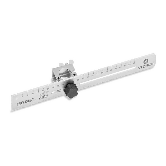
Beschreibung / Detailzeichnungen ISO DIST by ARTA Abb. 1: Vermessungselement mit Haltevorrichtung 2 = Haltevorrichtung 3 = Vermessungselement 5 = Verschiebevorrichtung 8 = Positionierraster (für Horizontal- bzw. Vertikalausrichtung) Abb. 2 + 3: Stirnseite des Vermessungselements 9 = Positionierraster (für Horizontalausrichtung) 10 = Positionierraster in Schrägstellung (für Vertikalausrichtung) 1 1 = Positionierloch... - Page 5 Abb. 4: Anbringen der Vermessungselemente am Arbeitsgerüst 1 = Stellrahmen 3 = Vermessungselemente 4 = Längsholm 6 = Abstandsmaß zur Wand 7 = Richtschnur...
- Page 6 Abb. 5: Anbringen der Vermessungselemente am Arbeitsgerüst 1 = Stellrahmen 3 = Vermessungselemente 4 = Längsholm 7 = Richtschnur...
-
Page 7: Arbeitsschritte
Arbeitsschritte Arbeitsgerüst: Als Grundlage dient ein Arbeitsgerüst, das wenigstens zwei Stellrahmen aufweisen muss (Nr. 1, Abb. 4+5). Diese sind parallel zueinander und im rechten Winkel zur Wand auszurichten. Von dem Arbeitsgerüst aus wird die Wand vermessen, die Fassadenverkleidung angebracht und später die Ausrichtung der Wand überprüft. -
Page 8: Garantie
Arbeitsschritte (weiter) Bemessen Sie für das Anbringen der Verkleidung den Abstand zwischen dem Arbeitsgerüst und der zu verkleidenden Wand von vorneherein so groß, dass die Fassadenverkleidung bzw. das WDVS ungehindert zwischen dem Gerüst und der Wand angebracht werden kann. Für diesen Arbeitsgang stellen Sie die Richtschnüre auf eine Referenzebene ein, die der Außenseite der Verkleidung entspricht. - Page 10 Hartelijk dank voor uw vertrouwen in STORCH. Met deze aankoop hebt u voor een kwaliteitsproduct gekozen. Als u desondanks een tip voor verbeteringen hebt of wellicht ooit een probleem ondervindt, dan horen wij graag van u. Neem contact op met de medewerker buitendienst of in dringende gevallen rechtstreeks met ons.
-
Page 11: Voorwoord
Voor schade die ontstaat uit het niet in acht nemen van deze informatie of schade die ontstaat vanwege ondeskundig gebruik, zijn we niet verantwoordelijk en kan er geen aanspraak op de garantie wor- den gedaan. Vervangende delen, verbruiksmateriaal Alle apparaatonderdelen zijn verkrijgbaar bij STORCH en de handelspartners. -
Page 12: Beschrijving / Detailtekening
Beschrijving / detailtekeningen ISO DIST by ARTA Afb. 1: Meetelement met houder 2 = Houder 3 = Meetelement 5 = Schuifinstallatie 8 = Positioneerraster (voor horizontale resp. verticale uitlijning) Afb. 2 + 3: Voorzijde van het meetelement 9 = Positioneerraster (voor horizontale uitlijning) 10 = Positioneerraster in schuine stand (voor verticale uitlijning) 1 1 = Positioneergat... - Page 13 Afb. 4: Aanbrengen van de meetelementen aan steiger 1 = Opbouwframe 3 = Meetelementen 4 = Lengtesteun 6 = Afstandsmaat tot de wand 7 = Richtlijn...
- Page 14 Afb. 5: Aanbrengen van de meetelementen aan steiger 1 = Opbouwframe 3 = Meetelementen 4 = Lengtesteun 7 = Richtlijn...
-
Page 15: Werkstappen
Werkstappen Steiger: Als basis dient een steiger met minimaal twee opbouwframes (nr. 1, afb. 4+5). Deze moeten parallel aan elkaar in een rechte hoek ten opzicht van de muur worden geplaatst. Vanaf de steiger wordt de muur gemeten, de gevelbekleding aangebracht en later de uitlijning van de wand gecontroleerd. -
Page 16: Garantie
Werkstappen (vervolg) Zorg voor het aanbrengen van de bekleding dat de afstand tussen de steiger en te bewerken muur van tevoren groot genoeg is zodat de bekleding/isolatie ongehinderd tussen de steiger en de muur kan worden aangebracht. Voor deze stap stelt u de richtlijnen op een referentievlak in dat overeenkomt met de buiten- kant van de bekleding. - Page 18 à votre disposition. Dans ce cas, contactez votre représentant, ou directement notre service clients, s'il s'agit d'un problème urgent. Salutations dévouées SAV STORCH Tél.: +49 (0) 2 02 . 49 20 - 112 Fax: +49 (0)2 02 . 49 20 - 244...
-
Page 19: Préface
Le dispositif de mesure doit être mis en oeuvre et utilisé dans les conditions énoncées dans cette notice. Nous déclinons toute responsabilité et toute garantie pour les dommages découlant de l'inobservation ou d'une manière d'agir incorrecte. Pièces détachées, matériel d'usage STORCH et ses partenaires de distribution tiennent à votre disposition toutes les pièces de l'appareil. -
Page 20: Description / Schéma Détaillé
Description / schémas détaillés ISO DIST by ARTA Fig. 1: élément de mesure avec dispositif de maintien 2 = dispositif de maintien 3 = élément de mesure 5 = dispositif de déplacement 8 = cran de positionnement (pour l'orientation verticale ou horizontale) Fig. - Page 21 Fig. 4: apporter les éléments de mesure sur l'échafaudage 1 = Cadre de fixation 3 = Eléments de mesure 4 = Longeron 6 = Gabarit d'écartement par rapport au mur 7 = Cordon d'alignement...
- Page 22 Fig. 5: apporter les éléments de mesure sur l'échafaudage 1 = Cadre de fixation 3 = Eléments de mesure 4 = Longeron 7 = Cordon d'alignement...
-
Page 23: Etapes De Travail
Etapes de travail Echafaudage: Un échafaudage qui doit présenter au moins deux cadres de base (No. 1, fig. 4 + 5) constitue la base. Ces deux cadres doivent être orientés parallèlement l'un à l'autre et perpendiculairement au mur. Le mur est mesuré depuis l'échafaudage, l'habillage de façade est apporté et plus tard l'orientation du mur contrôlé. -
Page 24: Garantie
Etapes de travail (suite) Pour apporter l'habillage, mesurer l'écart entre l'échafaudage et le mur devant être habillé dès le début de manière qu'il soit suffisant pour que l'habillage de façade ou le SCIT puisse être apporté sans gêne entre l'échafaudage et le mur. Pour cette étape de travail, régler les cordons d'alignement sur un niveau de réfé- rence qui correspond au côté... - Page 26 Grazie per la fiducia accordata a STORCH. Con l'acquisto avete scelto un prodotto di qualità. Se comunque avete dei suggerimenti volti a migliorare la nostra offerta o se doveste incontrare qualche difficoltà, non esitate a rivolgerVi a noi. Contattate il Vostro rappresentante oppure rivolgeteVi direttamente a noi in casi urgenti.
-
Page 27: Premessa
Il dispositivo di misura va utilizzato secondo le istruzioni della presente guida. Per danni da ricondurre alla non osservazione delle istruzioni oppure a procedimenti non idonei, decliniamo ogni responsabilità e richieste di garanzia. Pezzi di ricambio e materiale di consumo Tutte le parti del dispositivo sono reperibili all'azienda STORCH e dai loro partner commerciali. -
Page 28: Descrizione / Disegno Dettagliato
Descrizione / Disegni dettagliati ISO DIST by ARTA Ill. 1: Elemento di misura con dispositivo di supporto 2 = Dispositivo di supporto 3 = Elemento di misura 5 = Dispositivo di spostamento 8 = Griglia di posizionamento (per orientamento orizzontale ovv. verticale) Ill. - Page 29 Ill. 4: Applicazione degli elementi di misura al ponteggio di lavoro 1 = telaio 3 = elementi di misura 4 = trave longitudinale 6 = misura di distanza dal muro 7 = corda per tracciare...
- Page 30 Ill. 5: Applicazione degli elementi di misura al ponteggio di lavoro 1 = telaio 3 = elementi di misura 4 = trave longitudinale 7 = corda per tracciare...
-
Page 31: Fasi Di Lavoro
Fasi di lavoro Ponteggio di lavoro: Come base si utilizza un ponteggio di lavoro dotato di almeno due telai (n. 1, ill. 4+5). Essi devono essere orientati in posizione parallela l'uno all'altro ed in un angolo retto rispetto al muro. Stando sul ponteggio di lavoro, sarà... -
Page 32: Garanzia
Fasi di lavoro (continua) Al fine di montare il rivestimento, pianificare la distanza tra il ponteggio di lavoro ed il muro da rivestire in modo che il rivestimento di facciata ovv. il sistema composito di isolamento termico possa essere facil- mente montato tra il ponteggio di lavoro ed il muro. -
Page 34: Scope Of Delivery
Thank you for purchasing a STORCH product. You have purchased a quality product. If you would like to suggest an improvement, or experience a problem with your product, please do not hesitate to contact us. Please contact your field sales representative or, in urgent cases, contact us directly. -
Page 35: Preface
The measuring equipment must be deployed and operated in accordance with the conditions specified in this manual. We shall not assume any liability or warranty for damages resulting from non-compliance or improper handling. Spare parts, consumables All of the device components are available from STORCH and its distribution partners. -
Page 36: Description / Detailed Drawing
Description / detailed drawing ISO DIST by ARTA Fig. 1: Measuring element with bracket 2 = Bracket 3 = Measuring element 5 = Adjusting device 8 = Positioning grid (for horizontal or vertical alignment) Fig. 2 + 3: Front side of measuring element 9 = Positioning grid (for horizontal alignment) 10 = Positioning grid in inclined position (for vertical alignment) 1 1 = Positioning bore... - Page 37 Fig. 4: Attaching the measuring elements to the work scaffolding 1 = Assembly frame 3 = Measuring elements 4 = Longitudinal beam 6 = Clearance to wall 7 = Plumb line...
- Page 38 Fig. 5: Attaching the measuring elements to the work scaffolding 1 = Assembly frame 3 = Measuring elements 4 = Longitudinal beam 7 = Plumb line...
-
Page 39: Steps
Steps Work scaffolding: The basis is formed by a work scaffold which must comprise at least two assembly frames (No. 1, Fig. 4+5). They must be aligned parallel to one another and at right angles to the wall. The wall is measured from the work scaffold; the facade cladding is applied and the trueness of the wall is then verified. -
Page 40: Warranty
Steps (cont.) When setting the clearance for applying cladding, choose the clearance between the work scaffold and the wall to be clad to be sufficiently large to allow the facade cladding or ETICS to fit easily between the scaffolding and the wall. To do so, align the plumb lines in a plane that represents the outer side of the cladding. -
Page 42: Rozsah Dodávky
Děkujeme Vám za důvěru ve firmu STORCH. S nákupem výrobku jste se rozhodli pro kvalitní produkt. Pokud přesto máte podněty na zlepšení nebo možná nějaký problém, tak bychom byli velmi rádi, kdybyste se nám ozvali. Promluvte si s příslušným externím spolupracovníkem naší firmy nebo se v naléhavých případech obracejte přímo na nás. -
Page 43: Oblasti Použití
Měřící zařízení se musí používat za podmínek uvedených v tomto návodu. Za škody vzniklé nerespekto- váním návodu nebo neodborným zacházením odmítáme veškerou odpovědnost a výkony ze záruky. Náhradní díly, spotřební materiál Všechny díly zařízení obdržíte u společnosti STORCH a jejích prodejců a partnerů. -
Page 44: Kostenlose Bestell-Hotline: 08 00. 7 86
Popis / podrobné výkresy ISO DIST by ARTA Obr. 1: Měřící prvek s držákem 2 = držák 3 = měřící prvek 5 = manipulátor 8 = polohovací rastr (pro horizontální příp. vertikální směr) Obr. 2 + 3: čelní strana měřícího prvku 9 = polohovací... - Page 45 Obr. 4: Připevnění měřících prvků na pracovní lešení 1 = stavěcí rám 3 = měřící prvky 4 = podélný nosník 6 = vzdálenost od stěny 7 = směrová šňůra...
- Page 46 Obr. 5: Připevnění měřících prvků na pracovní lešení 1 = stavěcí rám 3 = měřící prvky 4 = podélný nosník 7 = směrová šňůra...
-
Page 47: Kostenlose Service-Hotline: 08 00. 7 86
Pracovní kroky Pracovní lešení Jako podklad slouží pracovní lešení, které musí vykazovat alespoň dva stavěcí rámy (č. 1, obr. 4+5). Ty je třeba směrovat paralelně jeden ke druhému a pod pravým úhlem ke stěně. Z pracovního lešení se zaměřuje stěna, montuje se obložení fasád a později se kontroluje směr stěny. Umístěte stavěcí... - Page 48 Pracovní kroky (dále) Pro namontování obložení vyměřte od začátku tak velkou vzdálenost mezi pracovním lešením a obkláda- nou stěnou, aby bylo možno mezi lešení a stěnu bez překážky namontovat obložení fasád příp. tepelně izolační systém. Pro tento pracovní krok nastavte směrovou šňůru na referenční rovinu, která odpovídá vnější...
- Page 52 (Základní sada) Telefon: +49 (0)2 02 . 49 20 - 0 26 36 10 ISO DIST Měřící přístroj pro obložení Telefax: +49 (0)2 02 . 49 20 - 111 fasád a tepelně izolační systémy (Přídavná sada) E-mail: info@storch.de Internet: www.storch.de...