Table des Matières
Publicité
Les langues disponibles
Les langues disponibles
Liens rapides
Helios Ventilatoren
MONTAGE- UND BETRIEBSVORSCHRIFT
INSTALLATION AND OPERATING INSTRUCTIONS
NOTICE DE MONTAGE ET D'UTILISATION
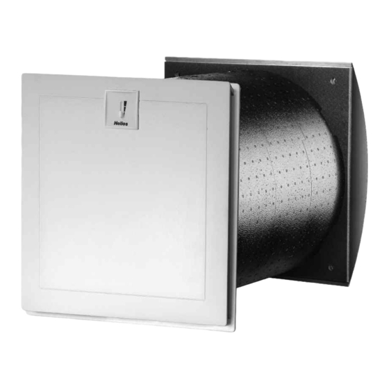
Wand-Einbaugerät
Wall installed unit
Groupe double-flux mural
KWL EC 60 Eco
Wärmerückgewinnung und EC-Technik
für Einzelräume
Heat recovery and EC-motor technology
for single rooms
Ventilation décentralisée avec récupération
de chaleur et moteurs EC
DE
EN
FR
Publicité
Chapitres
Table des Matières

Manuels Connexes pour Helios KWL EC 60 Eco


Sommaire des Matières pour Helios KWL EC 60 Eco
- Page 1 MONTAGE- UND BETRIEBSVORSCHRIFT INSTALLATION AND OPERATING INSTRUCTIONS NOTICE DE MONTAGE ET D’UTILISATION Wand-Einbaugerät Wall installed unit Groupe double-flux mural KWL EC 60 Eco Wärmerückgewinnung und EC-Technik für Einzelräume Heat recovery and EC-motor technology for single rooms Ventilation décentralisée avec récupération...
-
Page 2: Table Des Matières
Montage KWL EC 60 Eco Lüftungseinsatz ........ -
Page 3: Wichtige Informationen
Gewährleistung. 1 .6 Einsatzbereich – Anwendung Die Wärmerückgewinnungsgeräte KWL EC 60 Eco sind für den Einbau in Außenwände zur Be- und Entlüftung von kleinen und großen Einzelräumen vorgesehen. Für eine mittelgroße Wohneinheit wird die Installation von zwei Geräten empfohlen. -
Page 4: Elektrischer Anschluss
Montage- und Betriebsvorschrift Wand-Einbaugerät KWL EC 60 Eco 1 .10 Elektrischer Anschluss WARNUNG Vor allen Wartungs- und Installationsarbeiten oder vor Öffnen des Schaltraumes ist das Gerät allpolig vom Netz zu trennen! Der elektrische Anschluss darf nur von einer autorisierten Elektrofachkraft entsprechend den nach- stehenden Anschlussplänen ausgeführt werden . -
Page 5: Montage/Aufstellung
(Befestigungsschrauben aus Edelstahl bauseits) Wand mit Isolierung Abtropfblech Kondensatablauf ~ 350 rechts unten 3 .2 Montage KWL EC 60 Eco Lüftungseinsatz Abb .8 Netz.- und Steuerleitung Wandhülse anschließen und den Lüftungseinsatz in die Wandhülse einschieben Wand Kunststofffassade an der Innenwand bzw. -
Page 6: Montage Kwl 60 Dr Distanzrahmen
Typ A oder B mit einem Bemessungsdifferenzstrom von 30 mA. Der EC Ventilator hat einen Ableitstrom von ≤ 3,5 mA, ermittelt nach DIN EN 50178 Bild 4. 4 .1 Schaltplan SS-949 für KWL EC 60 Eco KWL EC 60 Eco Abb .11 2 x 1,5mm²... -
Page 7: Bedienelement Kwl 60 Bu
Netz zu trennen! Gefährdung durch elektrischen Schlag, bewegliche Teile (Gebläse) und heiße Oberflächen . – Filter Das KWL EC 60 Eco ist zu- und abluftseitig mit Klasse G4 Filter ausgestattet (nach DIN EN 1946, T.2): • Außenluft/Abluft: Ersatzluftfilter Grobfilter G4 ELF-KWL 60/4/4 Best .-Nr . - Page 8 Montage- und Betriebsvorschrift Wand-Einbaugerät KWL EC 60 Eco...
- Page 9 Montage- und Betriebsvorschrift Wand-Einbaugerät KWL EC 60 Eco...
- Page 10 Wiring diagram SS-949 for KWL EC 60 Eco ....... . .
-
Page 11: Important Information
Application - Operation The units with heat recovery KWL EC 60 Eco are designed for the installation in external walls to ventilate small and large single rooms. For a medium-sized flat the installation of two units is recommended The standard equipment per- mits the installation and the application in frost-free rooms>... -
Page 12: Electrical Connection
Installation and Operating Instructions Wall installed unit KWL EC 60 Eco 1 .10 Electrical connection WARNING All work must be carried out with the equipment fully isolated from the power supply . The electrical connection are to be carried out in accordance with the relevant wiring diagram and are only to be done by a certified electrician . -
Page 13: Montage / Installation
Installation and Operating Instructions Wall installed unit KWL EC 60 Eco 3 .0 Wall installation of KWL 60 RS first fix set CHAPTER 3 Drill a core hole in the external wall (see fig. 5). Then insert wall sleeve into the wall and plaster it in. -
Page 14: Installation Of Kwl 60 Dr Compensation Ring
Type A or B with a rated differential current of 30 mA. The EC fan has a leakage current of <= 3.5 mA, determined according to DIN EN 50178 image 4. 4 .1 Wiring diagram SS-949 for KWL EC 60 Eco fig .11 KWL EC 60 Eco 2 x 1,5mm²... -
Page 15: Speed Controller Kwl Ec 60 Bu
Danger by electrical impact, mobile parts (fan) and hot surfaces. – Filter The KWL EC 60 Eco is supplied with filters of class G4 in the supply and extract air stream (according to DIN EN 1946, T.2) • Supply air / Extract air... - Page 16 Montage de l’unité de ventilation KWL EC 60 Eco ....... .
-
Page 17: Chapitre 1 . Informations Generales
1 .6 Domaine d’utilisation Le groupe double-flux mural à récupération de chaleur KWL EC 60 Eco est conçu pour l’insufflation et l’extraction d’air dans les petits et grands locaux individuels. Pour les locaux nécessitant des débits d’air plus importants, nous conseil- lons l’utilisation de deux appareils. -
Page 18: Raccordement Électrique
Notice de montage et d’utilisation Groupe double-flux mural KWL EC 60 Eco 1 .10 Raccordement électrique ATTENTION Mettre impérativement l’appareil hors tension avant tous travaux d’entretien ou à l’ouverture du boîtier de commande ! Le branchement électrique doit être réalisé, conformément aux schémas de raccordement ci-des- sous, uniquement par un électricien qualifié... -
Page 19: Chapitre 3 . Montage / Disposition
Abtropfblech Kondensatablauf condensats, en ~ 350 rechts unten dessous à droite 3 .2 Montage de l’unité de ventilation KWL EC 60 Eco Fig . 8 Raccorder l’alimentation et la Netz.- und Steuerleitung Manchon mural Wandhülse commande puis insérer le groupe anschließen und den... -
Page 20: Raccordement Électrique
Type A ou B avec un courant différentiel de 30 mA. Le ventilateur EC a un débit de fuite <= 3,5 mA, selon DIN EN 50178 Fig. 4. 4 .1 Schéma électrique SS-949 pour KWL EC 60 Eco Fig .11 KWL EC 60 Eco 2 x 1,5mm²... -
Page 21: Chapitre 5 . Nettoyage Et Entretien
Commande à distance KWL 60 BU Le KWL EC 60 Eco se contrôle avec la commande à distance KWL 60 BU intégrée dans la façade. La commande à distance permet de naviguer entre trois vitesses via son interrupteur à glissière (fig. 12). - Page 23 KWL EC 60 Eco...
- Page 24 HELIOS Ventilatoren GmbH + Co KG · Lupfenstraße 8 · 78056 VS-Schwenningen HELIOS Ventilateurs · Le Carré des Aviateurs · 157 avenue Charles Floquet · 93155 Le Blanc Mesnil Cedex CH HELIOS Ventilatoren AG · Tannstrasse 4 · 8112 Otelfingen GB HELIOS Ventilation Systems Ltd.