Table des Matières
Publicité
Liens rapides
IT
MANUALE
TECNICO
Assistenza tecnica Italia
Commerciale Italia
Comelit Group S.p.A. - Via Don Arrigoni 5 - 24020 Rovetta S. Lorenzo BG Italy - tel. (+39) 0346 750 011 - fax (+39) 0346 71436
www.comelit.eu
www.simplehome.eu
EN
TECHNICAL
MANUAL
MT KIT 10
KIT VIDEO
BRAVO KIT COLOR
COLOR BRAVO KIT
COLOR BRAVO KIT
0346/750090
Technical service abroad (+39) 0346750092
0346/750091
Export department
info@comelit.it
commerciale.italia@comelit.it
FR
MANUEL
TECHNIQUE
(+39) 0346750093
export.department@comelit.it
Publicité
Chapitres
Table des Matières

Manuels Connexes pour Comelit Group MT KIT 10


Sommaire des Matières pour Comelit Group MT KIT 10
- Page 1 Assistenza tecnica Italia Commerciale Italia 0346/750091 Export department (+39) 0346750093 Comelit Group S.p.A. - Via Don Arrigoni 5 - 24020 Rovetta S. Lorenzo BG Italy - tel. (+39) 0346 750 011 - fax (+39) 0346 71436 www.comelit.eu www.simplehome.eu info@comelit.it commerciale.italia@comelit.it...
- Page 2 • Install the equipment by carefully following the instructions given by the manufacturer and in compliance with the legislation in force. • All the equipment must only be used for the purpose it was built for. Comelit Group S.p.A. declines any responsibility for improper use of the apparatus, for modifications made by others under any title or scope, and for the use of accessories and materials which...
- Page 3 MT KIT 10 KIT VIDEO BRAVO KIT COLOR SOMMARIO SCHEMI DI COLLEGAMENTO • GENERALITÀ pag. • - BK/01C Schema base per kit monofamiliari Art. 8184 pag. 73 - BK/02BC Schema base per kit bifamiliari Art. 8185 POSTI ESTERNI • con collegamento in derivazione pag.
- Page 4 Il pulsante dell'articolo 4875KC è impostato di fabbrica per effettuare la chiamata all'indirizzo 1 mentre per l'articolo 4876KC i pulsanti sono impostati per effettuare chiamate agli indirizzi 1 (pulsante sinistro) e 2 (pulsante destro). Dimensione posto esterno: 125x125 mm. MT KIT 10...
- Page 5 MT KIT 10 Istruzioni di installazione Art. 4875KC, 4876KC • Murare la scatola a 160÷165 cm • Togliere il frontalino in acciaio dal pavimento finito, inox per eseguire le regolazioni in una zona agevole per la dei volumi e l’orientamento ripresa del visitatore.
- Page 6 7. Frontalino di serie personalizzabile con Kit di personalizzazione. 8. Pulsante disponibile di serie, utilizzabile per usi vari (contatto C.NO. 1A max) a seconda delle necessità di impianto; rimuovendo CV3 e CV4 come riportato nella variante BK/PC a pag. 89. MT KIT 10...
- Page 7 MT KIT 10 Installazione monitor Art. 5702 a parete Art. 5714KC cm 10,2 cm 11 cm 14,4 cm 1,4 cm 8,1 Staffa di fissaggio del monitor cm 1,4 La staffa di fissaggio Art. 5714KC consente l’installazione del Monitor a muro o tramite la base da tavolo Art. 5712 (per maggiori informazioni vedi pagina 5, 6).
- Page 8 GROUP S.P.A. Montaggio Monitor Art. 5702 sulla base Procedura per togliere il Monitor da tavolo Art. 5712 Posizionamento etichetta sul monitor MT KIT 10...
- Page 9 MT KIT 10 Istruzioni di installazione Scheda opzionale Art. 5733, Art. 5734 D IP 5734 5734 ! 1 Estrarre la staffa e la scheda opzionale dalla propria confezione. 2 Avvitare la scheda opzionale con le apposite viti sul supporto plastico della staffa.
- Page 10 GROUP S.P.A. Istruzioni per installazione citofono Style Art. 2608, 2628 e 2610 95mm 47,5mm 75,5mm 215mm fl 5mm max fl 5mm max Cover intercambiabile disponibile per gli Art. 2628 e Art. 2610 MT KIT 10...
- Page 11 MT KIT 10 Citofono Style Art. 2608 Citofono Basic con 2 pulsanti di serie. Non è utilizzabile per sfruttare la funzione intercomunicante. Il Citofono va montato sempre utilizzando l’Art. 1214/2C come mostrato nello schema di collegamento BK/DC a pagina 84.
- Page 12 (A) Pulsante disponibile con scheda opzionale Art. 1626. Led di visualizzazione disponibile con scheda opzionale Art. 1627. ATTENZIONE ! PER UTILIZZARE IL CITOFONO ART. 2628 IN IMPIANTI BRAVOKIT È NECESSARIO SPOSTARE IL JUMPER JP1 IN POSIZIONE S1 MT KIT 10...
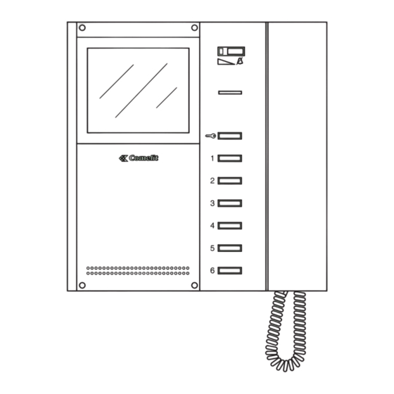
- Page 13 MT KIT 10 Citofono Style Art. 2610 Citofono Elegance con funzioni e pulsanti supplementari e 11. Morsetti connessione impianto: servizio intercomunicante. L L connessione alla linea bus. CFP CFP ingresso chiamata da piano. L’Art. 2610 ha la possibilità, (mediante apposito settaggio) di P2 C2 morsetti pulsante P2 C.
- Page 14 * Nel caso si utilizzi un cavo multicoppiola usare una sola delle coppiole disponibili. Nel caso sia necessario diminuire le cadute resistive utilizzare la singola coppiola come singolo filo. ** Nel caso si utilizzi un cavo multipolare usare solo due dei fili disponibili e non utilizzare mai fili in parallelo. MT KIT 10...
- Page 15 MT KIT 10 1216 1214KC 1216 1214KC 1212/B 1205/B 4833C 1205/B 4875KC 4876KC 1395 4875KC 4875KC 4876KC 4876KC Tabella Impostazioni dell’Art. 1216 in funzione del tipo di cavo di connessione utilizzato Tipo di cavo Impostazione Art. 1216 Cavo bifilare (sez. 0,5 mm Ø...
- Page 16 La figura seguente mostra la posizione dei micro-interruttori e del Jumper JP1 della staffa 5714KC e dei micro-interruttori dei citofoni Style Art. 2608, 2628 e 2610. D I P S1-1 S1-2 S1-3 S1-4 S1-5 S1-6 S1-7 S1-8 S1-5 S1-4 S1-3 S1-2 S1-1 MT KIT 10...
- Page 17 MT KIT 10 I valori di S1-1, S1-2, S1-3, S1-4 e S1-5 definiscono l’indirizzo di chiamata. Per la codifica sia delle staffe che dei citofoni fare riferimento alla seguente tabella. Tabella di programmazione dei Micro interruttori per codice utente su Staffe e citofoni...
- Page 18 La chiamata intercomunicante bifamiliare (tra citofoni e/o videocitofoni) è possibile solo se i due utenti sono impostati su codici di chiamata contigui (contrassegnati dalla stessa lettera AA…CC..YY nella tabella di programmazione dei Micro interruttori riportata a pagina 15). MT KIT 10...
- Page 19 MT KIT 10 MICRO-INTERRUTTORI S1-1, S1-2, S1-3, S1-4 E S1-5 Anche senza sollevare la cornetta si ha la possibilità di visualizzare l’immagine trasmessa dal posto esterno, sempre premendo il Pulsante 2 - richiesta video. I valori dei micro-interruttori S1-1, S1-2, S1-3, S1-4 e S1-5 definiscono l’indirizzo di chiamata della staffa in oggetto nei...
- Page 20 Una chiamata intercomunicante non è prioritaria rispetto ad una conversazione/chiamata con il posto esterno. In questo caso, durante un tentativo di chiamata intercomunicante, il LED di segnalazione lampeggerà per alcuni secondi per segnalare che il sistema è occupato. MT KIT 10...
- Page 21 MT KIT 10 Impostazione citofono (opzionale) Art. 2610 Funzione Autoaccensione e Richiesta Video Funzione Autoaccensione (consigliata solo per impianti con 1 Nel caso si decida di ampliare il sistema BRAVO KIT con o 2 ingressi). L’ accensione del monitor avviene premendo e l’aggiunta di un Citofono opzionale Art.
- Page 22 Comando apriporta normalmente aperto (NO) (impostazione di fabbrica) 2,4,5,6,7,8 Comando Apriporta normalmente chiuso (NC) 1,2,4,5,6,7,8 Apriporta attivo anche in assenza di chiamata (impostazione di fabbrica) 3,4,5,6,7,8 Apriporta abilitato solo per l'utente chiamato 1,3,4,5,6,7,8 Ripristino di tutte le impostazioni di fabbrica 2,3,4,5,6,7,8 MT KIT 10...
- Page 23 MT KIT 10 ESPANDIBILITÀ DEL SISTEMA BRAVO KIT Negli schemi BK/EN/100C e BK/EN/101C a pag. 90, 92 riportati dell'Art. 4660C a bordo dell'Art. 4875KC o 4876KC come descritto nella sezione A di questo manuale viene mostrata una possibile nella seguente procedura e le staffe 5714KC con il codice configurazione d’impianto che offre la possibilità...
- Page 24 Pag. 76 Schema per kit monofamiliare con alimentatore Collegamento in derivazione aggiuntivo Art. 1395 Schema base per kit bifamiliari Art. 8185. Per i conduttori da utilizzare e per le distanze massime di funzio- Schema BK/01/AC Pag. 80 MT KIT 10...
- Page 25 MT KIT 10 DESCRIZIONE VARIANTI DI COLLEGAMENTO BRAVO KIT è possibile comandare il relè a bordo dell’attuatore tramite i pulsanti dedicati sul monitor e/o citofono. Portata relè attuatore: 10A. Per le modalità d’uso dell’Art. 1256 Utilizzo modulo telecamera scorporata Art. 1259C rifarsi al foglio tecnico FT SB2 02 dello stesso articolo.
-
Page 27: Table Des Matières
MT KIT 10 BRAVO KIT COLOR VIDEO KIT SUMMARY CONNECTION DIAGRAMS • GENERAL INFORMATION page 26 • - BK/01C Main diagram for single-residence kits Art. 8184. page 73 - BK/02BC Main diagram for two-residence kits Art. 8185 EXTERNAL UNITS •... -
Page 28: General Information
Flush-mounted box dimensions: 127x127x45 mm. The pushbutton of article 4875KC is factory-set to call address 1, whereas for article 4876KC the pushbuttons are set to call addresses 1 (left pushbutton) and 2 (right pushbutton). External unit dimensions: 125x125 mm. MT KIT 10... -
Page 29: Installation Instructions Art. 4875Kc, 4876Kc
MT KIT 10 Installation instructions Art. 4875KC, 4876KC • Wall-mount the box 160÷165 cm • Remove the stainless steel front from the finished floor, to carry out volume adjustments in an area where it is easy to see and adjust the camera. -
Page 30: Internal Units
(C.NO. contact 1A max.) according to system needs; removing CV3 and CV4 as given in the variant BK/PC on page 89. 9. Pushbutton available standard. 10. Optional pushbuttons (using card Art. 5733 or Art. 5734) for activating additional functions. MT KIT 10... -
Page 31: Wall-Mounting Of Monitor Art. 5702
MT KIT 10 Wall-mounting of monitor Art. 5702 Art. 5714KC cm 10,2 cm 11 cm 14,4 cm 1,4 cm 8,1 Monitor fixing bracket cm 1,4 The fixing bracket Art. 5714KC enables wall-mounting of the Monitor or installation by means of desktop base Art. 5712 (for more information see page 29, 30). -
Page 32: Mounting Monitor Art. 5702 On Desktop Base Art. 5712
GROUP S.P.A. Mounting Monitor Art. 5702 on desktop Procedure for removing the Monitor base Art. 5712 Positioning of label on monitor MT KIT 10... - Page 33 MT KIT 10 Optional card Art. 5733, Art. 5734 installation instructions D IP 5734 5734 ! 1 Remove the bracket and optional card from their package. 2 Secure the optional card on the plastic support of the bracket with the special screws.
- Page 34 GROUP S.P.A. Style interphone Art. 2608, 2628 and 2610 installation instructions 95mm 47,5mm 75,5mm 215mm fl 5mm max fl 5mm max Interchangeable cover available for Art. 2628 and Art. 2610 MT KIT 10...
-
Page 35: Style Interphone Art. 2608
MT KIT 10 Style interphone Art. 2608 Basic interphone with 2 pushbuttons standard. Cannot be used for the intercom function. The Interphone must always be mounted using Art. 1214/2C as shown in the BK/DC connection diagram on page 84. 1. Door lock release pushbutton 2. -
Page 36: Style Interphone Art. 2628
10. Interphone handset (lift the handset to start communication). (A) Pushbutton available with optional card Art. 1626. Display LED available with optional card Art. 1627. ATTENTION ! TO USE INTERPHONE ART. 2628 IN BRAVO KIT SYSTEMS, JUMPER JP1 MUST BE SHIFTED TO POSITION S1 MT KIT 10... -
Page 37: Style Interphone Art. 2610
MT KIT 10 Style interphone Art. 2610 Elegance interphone with additional functions and 11. System connection terminals: pushbuttons and intercom service. L L bus line connection. CFP CFP floor door call input. P2 C2 pushbutton P2 C terminals. NO. 24V 100mA dedicated By means of special setting, Art. -
Page 38: General Installation And Operation Instructions
* In case of multipair cable, it is advisable to use only one of the pairs for the system. To reduce resistive drops, use a single pair as a single wire. ** In case of multicore cable, use only two of the available wires and never use wires in parallel. MT KIT 10... -
Page 39: Table Of Settings Art. 1216
MT KIT 10 1216 1214KC 1216 1214KC 1212/B 1205/B 4833C 1205/B 4875KC 4876KC 1395 4875KC 4875KC 4876KC 4876KC Table of Settings Art. 1216 according to the type of connection cable used Type of cable Setting Art. 1216 Double-wire cable (section 0.5 mm Ø... - Page 40 The following figure shows the position of the microswitches and Jumper JP1 of bracket 5714KC and the microswitches of Style interphones Art. 2608, 2628 and 2610. D I P S1-1 S1-2 S1-3 S1-4 S1-5 S1-6 S1-7 S1-8 S1-5 S1-4 S1-3 S1-2 S1-1 MT KIT 10...
-
Page 41: Setting Of Bracket Art. 5714Kc Main Or Secondary
MT KIT 10 The values of S1-1, S1-2, S1-3, S1-4 and S1-5 define the call address. Refer to the following table for the coding of brackets and interphones. Table of user code programming microswitches on Brackets and interphones Reference for... - Page 42 The two-residence intercom call (between interphones and/or video doorphones) is possible only if the two users are set to contiguous call codes (marked with the same letter AA…CC..YY in the Microswitch programming table given on page 39). MT KIT 10...
- Page 43 MT KIT 10 MICROSWITCHES S1-1, S1-2, S1-3, S1-4 AND S1-5 without lifting the handset, simply by pressing Pushbutton 2 - video request. In the classic BRAVO KIT configuration, it is therefore possible to The values of the microswitches S1-1, S1-2, S1-3, S1-4 and S1-5...
-
Page 44: Monitor Ringtone Selection Procedure
Video doorphone and/or Interphone where the function was activated, by the external unit. With the function activated, the signalling LED stays on. The Doctor function is enabled or disabled by pressing the pushbutton set for that function for 2 seconds. MT KIT 10... -
Page 45: Setting Of Optional Interphone Art. 2610
MT KIT 10 Setting interphone (optional) Art. 2610 Video request and Automatic Switch-on function Automatic Switch-on function (recommended only for systems To extend the BRAVO KIT system by adding the optional with 1 or 2 entrances). Press and immediately release the Interphone Art. -
Page 46: Special Programming Art. 4660Kc
Door lock release control normally open (NO) (factory setting) 2,4,5,6,7,8 Door lock release control normally closed (NC) 1,2,4,5,6,7,8 Door lock release active even with no call (factory setting) 3,4,5,6,7,8 Door lock release only enabled for the user called 1,3,4,5,6,7,8 Reset of all factory settings 2,3,4,5,6,7,8 MT KIT 10... -
Page 47: Bravo Kit System Expandability
MT KIT 10 BRAVO KIT SYSTEM EXPANDABILITY The diagrams BK/EN/100C and BK/EN/101C on page 90, 92, in of Art. 4660C on Art. 4875KC or 4876KC as described in the section A of this manual, show a possible system configuration following procedure, and the brackets 5714KC with the for managing up to a max. -
Page 48: Description Of Bravo Kit Connection Diagrams
Diagram for single-family kit with additional power Branch connection feeder Art. 1395 Main diagram for two-residence kits Art. 8185. Refer to the indications on page 36 for the wires to be used and Diagram BK/01/AC Page 80 MT KIT 10... -
Page 49: Connection
MT KIT 10 DESCRIPTION OF BRAVO KIT CONNECTION VARIANTS Addition of actuator Art. 1256 Diagram BK/AC Page 86 Use of remote camera module Art. 1259C By connecting Art. 1256 in parallel to the terminals of bracket 5714KC the relay on the actuator can be controlled using the... - Page 51 MT KIT 10 KIT VIDÉO BRAVO KIT COLOR SOMMAIRE SCHÉMAS DE BRANCHEMENT • GÉNÉRALITÉS page 50 • - BK/01C Schéma base pour kit un appartement Art. 8184. page 73 - BK/02BC Schéma base pour kit deux appartements POSTES EXTÉRIEURS •...
-
Page 52: Généralités
Le bouton de l’article 4875KC est réglé en usine pour effectuer l’appel à l’adresse 1 alors que pour l’article 4876KC les boutons sont programmés pour effectuer des appels aux adresses 1 (bouton de gauche) et 2 (bouton de droite). Dimensions poste externe : 125x125 mm. MT KIT 10... -
Page 53: Instructions D'installation Art. 4875Kc, 4876Kc
MT KIT 10 Instructions d’installation Art. 4875KC, 4876KC • Murer le boîtier à 160÷165 cm • Enlever la façade en acier inox du sol fini, pour effectuer les réglages des dans une zone aisée pour voir le volumes et l’orientation de la visiteur. -
Page 54: Postes Intérieurs
7. Façade de série personnalisable avec le kit de personnalisation. 8. Bouton disponible de série, utilisable pour divers usages (contact C.NO. 1A max) selon les besoins d’installation ; en retirant CV3 et CV4 comme indiqué dans la variante BK/PC page 89. MT KIT 10... -
Page 55: Installation Moniteur Art. 5702 Mural
MT KIT 10 Installation moniteur Art. 5702 mural Art. 5714KC cm 10,2 cm 11 cm 14,4 cm 1,4 cm 8,1 Bride de fixation du moniteur cm 1,4 Le bride de fixation Art. 5714KC permet d’installer le moniteur en saillie ou avec la base de table Art. 5712 (pour plus d’informations voir page 53, 54). -
Page 56: Art. 5712
GROUP S.P.A. Installation moniteur Art. 5702 sur la base Procédure pour enlever le moniteur de table Art. 5712 Positionnement étiquette sur moniteur MT KIT 10... -
Page 57: Instructions D'installation Carte En Option Art. 5733, Art. 5734
MT KIT 10 Instructions d’installation Carte option Art. 5733, Art. 5734 D IP 5734 5734 ! 1 Extrayez la bride et la carte en option de leurs emballages. 2 Vissez la carte option avec les vis spéciales sur le support plastique de la bride. -
Page 58: Instructions Pour Installation Combiné Parlophonique Style Art. 2608, 2628 Et 2610
GROUP S.P.A. Instructions pour installation combiné parlophonique Style Art. 2608, 2628 et 2610 95mm 47,5mm 75,5mm 215mm fl 5mm max fl 5mm max Façade interchangeable disponible pour les Art. 2628 et Art. 2610 MT KIT 10... -
Page 59: Combiné Style Art. 2608
MT KIT 10 Combiné parlophonique Style Art. 2608 Combiné parlophonique Basic avec 2 boutons de série. Non utilisable pour la fonction intercommunicante. Le combiné parlophonique doit être monté en utilisant l’Art. 1214/2C comme l’indique le schéma de connexion BK/DC page 84. -
Page 60: Combiné Style Art. 2628
(A) Bouton disponible avec carte en option Art. 1626. Voyant de signal disponible avec la carte en option Art. 1627. ATTENTION ! POUR UTILISER LE COMBINÉ PARLOPHONIQUE ART. 2628 DANS DES INSTALLATIONS BRAVOKIT, IL EST NÉCESSAIRE DE DÉPLACER LE CAVALIER JP1 EN POSITION S1 MT KIT 10... -
Page 61: Combiné Style Art. 2610
MT KIT 10 Combiné parlophonique Style Art. 2610 Combiné parlophonique Elegance avec fonctions et boutons 11. Bornes pour le raccordement de l’installation : supplémentaires et service intercommunicant. L L connexion à la ligne bus. CFP CFP entrée de l’appel depuis l’étage. -
Page 62: Indications Générales D'installation Et Fonctionnement
S’il est nécessaire de diminuer les chutes résistives, utiliser la paire torsadée comme un fil simple. ** Dans le cas d’un câble multifils, il ne faut utiliser que deux des fils disponibles et ne jamais mettre plusieurs fils en parallèle. MT KIT 10... - Page 63 MT KIT 10 1216 1214KC 1216 1214KC 1212/B 1205/B 4833C 1205/B 4875KC 4876KC 1395 4875KC 4875KC 4876KC 4876KC Tableau programmations de l’Art. 1216 en fonction du type de câble de connexion utilisé Type de câble Programmation Art. 1216 Câble bifilaire (sect.
-
Page 64: Programmations Et Description Fonctionnement Systeme Bravo Kit
La figure suivante montre la position des microswitches et du cavalier JP1 de la bride 5714KC et des microswitches des combinés parlophoniques Style Art. 2608, 2628 et 2610. D I P S1-1 S1-2 S1-3 S1-4 S1-5 S1-6 S1-7 S1-8 S1-5 S1-4 S1-3 S1-2 S1-1 MT KIT 10... -
Page 65: Tableau De Programmation Microswitches Pour Code Usager Sur Brides Et Combinés Parlophoniques
MT KIT 10 Les valeurs de S1-1, S1-2, S1-3, S1-4 et S1-5 définissent l’adresse d’appel. Pour le codage des brides et des combinés parlophoniques, se référer au tableau suivant. Tableau de programmation des microswitches pour code usager sur brides et combinés parlophoniques Référence pour... - Page 66 L’appel intercommunicant deux appartements (entre les combinés parlophoniques et/ou les visiophones) n’est possible que si les deux usagers sont réglés sur des codes d’appel contigus (marqués par la même lettre AA…CC..YY dans le tableau de programmation des microswitches illustré page 63). MT KIT 10...
-
Page 67: Description Programmations Et Fonctions Boutons
MT KIT 10 MICROSWITCHES S1-1, S1-2, S1-3, S1-4 ET S1-5 À ce stade, le moniteur du visiophone principal s’éteint et l’image s’affiche au moniteur du visiophone sur lequel on a appuyé sur le Bouton 2 - Demande vidéo. Les valeurs des microswitches S1-1, S1-2, S1-3, S1-4 et S1-5 Même sans soulever le combiné, il est possible de visualiser... - Page 68 Pour prendre l’appel provenant de l’unité extérieure, il suffit de saisir le combiné d’une unité disponible ou de raccrocher, puis de saisir le combiné d’une unité occupée par une communication intercommunicante. MT KIT 10...
-
Page 69: Programmation Combiné Parlophonique Option Art. 2610
MT KIT 10 Programmation combiné parlophonique (option) Art. 2610 Fonction auto-allumage et demande vidéo Fonction Auto-allumage (conseillée uniquement pour les Si vous décidez d’augmenter le système BRAVO KIT en ajoutant installations avec 1 ou 2 entrées). un combiné parlophonique en option Art. 2610, veuillez trouver ci- Pour allumer le moniteur, appuyer sur le bouton 2 et le relâcher... -
Page 70: Programmations Spéciales Art. 4660Kc
Commande ouvre-porte normalement ouvert (NO) (réglage d’usine) 2,4,5,6,7,8 Commande Ouvre-porte normalement fermé (NF) 1,2,4,5,6,7,8 Ouvre-porte actif également en absence d’appel (réglage d’usine) 3,4,5,6,7,8 Ouvre-porte validé seulement pour l’usager appelé 1,3,4,5,6,7,8 Restauration de tous les réglages d’usine 2,3,4,5,6,7,8 MT KIT 10... -
Page 71: Modularité Du Système Bravo Kit
MT KIT 10 MODULARITÉ DU SYSTÈME BRAVO KIT Les schémas BK/EN/100C et BK/EN/101C pages 90 et 92 boutons de l’Art. 4660C embarqué sur l’Art. 4875KC ou 4876KC contenus à la section A de ce manuel illustrent une configuration comme décrit dans la procédure suivante et les brides 5714KC avec d’installation possible, offrant la possibilité... -
Page 72: Description Schemas De Connexion Bravo Kit
Schéma BK/03BC Page 76 appartement. Connexion en dérivation Schéma base pour kit deux appartements Art. 8185 Schéma BK/04AC Page 79 Pour les conducteurs à utiliser et pour les distances maximums de Connexion en cascade MT KIT 10... -
Page 73: Connexion En Cascade
MT KIT 10 Schéma pour kit un appartement avec alimentateur face à la plaque de rue. Pour les modalités d’emploi de l’Art. 1256, voir la feuille technique FT SB2 02 de cet article. complémentaire Art. 1395. Schéma BK/01/AC page 80 Adjonction actionneur Art. - Page 74 BK/HC • BK/IC • BK/CC • BK/DC • BKC/AAB • BKC/AAA • BK/EC • BK/AC • BK/OC • BK/OAC • SB2/AAK • GEN/AAB • VARIANTE A • VARIANT A BK/PC • BK/NC • BK/EN/100C • BK/EN/101C • MT KIT 10...
-
Page 75: Bk/01C
MT KIT 10 BK/01C Schema base per kit monofamiliari Art. 8184. Basic wiring diagram for single-family kits Art. 8184. Schéma base pour kit un appartement Art. 8184. A (max) B (max) C (max) 0,5 mm (Ø 0,8 mm - Ø 8/10 AWG 20) -
Page 76: Bk/02Bc
N.B. Le impostazioni di S1-6, S1-7 e S1-8 sono in funzione della configurazione desiderata (vedi tabella a pag 16). NOTE: The S1-6, S1-7 and S1-8 settings depend on the configuration required (see table on page 40). NOTE: Les programmations de S1-6, S1-7 et S1-8 sont en fonction de la configuration désirée (voir tableau page 64). MT KIT 10... -
Page 77: Bk/02Ac
MT KIT 10 BK/02AC Schema base per kit bifamiliari Art. 8185 con collegamento in cascata. Basic wiring diagram for two-family kits Art. 8185 with connection in cascade. Schéma base pour kit deux appartements Art. 8185 avec connexion en cascade. A (max) -
Page 78: Bk/03Bc
N.B. Le impostazioni di S1-6, S1-7 e S1-8 sono in funzione della configurazione desiderata (vedi tabella a pag 16). NOTE: The S1-6, S1-7 and S1-8 settings depend on the configuration required (see table on page 40). NOTE: Les programmations de S1-6, S1-7 et S1-8 sont en fonction de la configuration désirée (voir tableau page 64). MT KIT 10... -
Page 79: Bk/03Ac
MT KIT 10 BK/03AC Schema per kit bifamiliari Art. 8185 ampliati con un secondo Art. 4876KC. Collegamento in cascata. Basic wiring diagram for two-family kit Art. 8185 expanded with a second Art. 4876KC. Cascade connection. Schéma pour kit deux appartements Art. 8185 avec un second Art. 4876KC. Connexion en cascade. -
Page 80: Bk/04Bc
N.B. Le impostazioni di S1-6, S1-7 e S1-8 sono in funzione della configurazione desiderata (vedi tabella a pag 16). NOTE: The S1-6, S1-7 and S1-8 settings depend on the configuration required (see table on page 40). NOTE: Les programmations de S1-6, S1-7 et S1-8 sont en fonction de la configuration désirée (voir tableau page 64). MT KIT 10... -
Page 81: Bk/04Ac
MT KIT 10 BK/04AC Schema per kit bifamiliari ampliati con un secondo Art. 4876KC, un’ulteriore monitor principale e un citofono per ciascuna unita’ familiare. Collegamento in cascata. Wiring diagram for two-family kit expanded with a second Art. 4876KC, an additional main monitor and a telephone for each family unit. -
Page 82: Bk/01/Ac
N.B. Le impostazioni di S1-6, S1-7 e S1-8 sono in funzione della configurazione desiderata (vedi tabella a pag 16). NOTE: The S1-6, S1-7 and S1-8 settings depend on the configuration required (see table on page 40). NOTE: Les programmations de S1-6, S1-7 et S1-8 sont en fonction de la configuration désirée (voir tableau page 64). MT KIT 10... -
Page 83: Bk/05C
MT KIT 10 BK/05C Utilizzo modulo telecamera scorporata Art. 1259C. Use of remote camera module Art. 1259C. Utilisation module caméra déportée Art. 1259C. Da alimentare separatamente To be powered separately À alimenter séparément Per settaggio e funzionamento Art. 1259C vedi FT/SBC/05. -
Page 84: Sb2/Aar
NOTE: The two internal units must have the same user address. The S1-6, S1-7 and S1-8 settings depend on the configuration required (see table on page 40). NOTE: Les deux postes internes doivent avoir la même adresse utilisateur. Les programmations de S1-6, S1-7 et S1-8 sont en fonction de la configuration désirée (voir tableau page 64). MT KIT 10... -
Page 85: Bk/Ic
MT KIT 10 BK/IC Aggiunta di un monitor principale in parallelo, collegamento in derivazione. Addition of a main monitor in parallel, with branched connection. Adjonction d’un moniteur principal en parallèle. Connexion en dérivation. MONITOR PRINCIPALE MONITOR PRINCIPALE MAIN MONITOR MAIN MONITOR... -
Page 86: Bk/Dc
Addition of a parallel telephone. Branch connection from riser. Adjonction d’un combiné parlophonique en parallèle en dérivation du montant. BKC/AAB Collegamento citofoni aggiuntivi in derivazione dal monitor. Connection of additional telephones, branch connection from monitor. Connexion combinés parlophoniques supplémentaires en dérivation du moniteur. MT KIT 10... -
Page 87: Bkc/Aaa
MT KIT 10 BKC/AAA Collegamento citofoni aggiuntivi in cascata dal monitor. Connection of additional telephones, connection in cascade from monitor. Connexion combinés parlophoniques supplémentaires en cascade du moniteur. BK/EC Aggiunta pilotaggio luce esterna tramite Art. 1256. Addition of external light control using of Art. 1256. -
Page 88: Bk/Ac
NOTE: Les programmations de S1-6, S1-7 et S1-8 sont en fonction de la configuration désirée (voir tableau page 64). BK/OC Variante collegamento apriporta locale temporizzato. Variant to connect the timed local button (Request to Exit). Variante pour connecter le bouton de commande de gâche local temporisé. MT KIT 10... -
Page 89: Bk/Oac
MT KIT 10 BK/OAC Variante utilizzo segnalazione PORTA APERTA. DOOR OPEN signalling use variant. Variante utilisation signalisation PORTE OUVERTE. Contatto N.C. per segnalazione PORTA APERTA (il led dei posti interni lampeggia). N.C. contact for DOOR OPEN signalling (the LED of the internal units flashes). -
Page 90: Gen/Aab
In case of more telephones or brackets with the same user code, connect the CFP button only on one; all devices will ring together. Si le même code utilisateur est attribué à plusieurs combinés parlophoniques, reliez le bouton CFP à l'un d'entre eux uniquement; tous les appareils sonneront simultanément. 20m MAX MT KIT 10... -
Page 91: Bk/Pc
MT KIT 10 BK/PC Utilizzo pulsante 1 per usi vari. Use of pushbutton 1 for various purposes. Emploi bouton 1 pour usages divers. 1205/B N.B. Le impostazioni di S1-6, S1-7 e S1-8 sono in funzione della configurazione desiderata (vedi tabella a pag 16). -
Page 92: Bk/En/100C
Art. 1224A, refer to the MT/SBC/01 technical manual. Pour plus de détails sur les distances d’utilisation de l'Art. 4833C et de l'Art. 4834/9, ainsi que pour plus de détails sur les réglages nécessaires par rapport à l'Art. 1224A, faire référence au manuel technique MT/SBC/01. MT KIT 10... - Page 93 MT KIT 10 4875KC Pulsante comando apriporta locale Local door-opener pushbutton control Bouton commande ouvre-porte local MT KIT 10...
-
Page 94: Bk/En/101C
1224A regarding the settings required for Art. 1224A, refer to les réglages nécessaires pour l'Art. 1224A, faire fare riferimento al manuale tecnico MT/SBC/01. the MT/SBC/01 technical manual. référence au manuel technique MT/SBC/01. MT KIT 10... - Page 95 MT KIT 10 4875KC 4875KC Pulsante comando apriporta locale Local door-opener pushbutton control Bouton commande ouvre-porte local MT KIT 10...
- Page 96 Technical service abroad Commerciale Italia 0346/750091 Export department (+39) 0346750093 [ B ] Comelit Group Belgium Comelit Group Germany GmbH [ E ] Comelit Espana S.L. [ F ] Comelit Immotec [ D ] Z.3 Doornveld 170 Brusseler Allee 23- 41812 Erkelenz Josef Estivill 67/69 - 08027 Barcelona Siège:...