Publicité
Liens rapides
B
M1
09.2001/2405-4700
XC/300
BPT S.p.A.
30020 Cinto Caomaggiore
Venezia/Italy
ISTRUZIONI PER L'USO
I
E INSTALLAZIONE
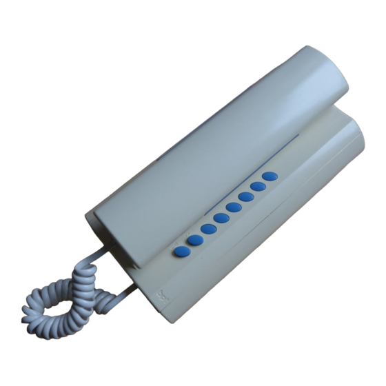
MODULO CITOFONO XC/300
È munito dei seguenti comandi (fig. 1):
•
Servizi ausiliari/chiamata portiere
•
Apriporta (
1
)
(
1
) E' possibile utilizzare questo comando solo se
l'apparecchio è attivo.
Funzione dei morsetti
Morsettiera M1
B linea
chiamata dal pianerottolo
–
massa
1
Funzione del ponticello SW1
Normalmente viene fornito inserito. Togliere il pon-
ticello qualora si voglia attenuare il volume della
nota di chiamata (fig. 2).
Caratteristiche tecniche
• Alimentazione: dalla stessa linea dati.
• Assorbimento: 0,5 mA.
• Linea di collegamento audio/dati: doppino non
polarizzato Z = 100 Ω.
• Temperatura di funzionamento: da 0 °C a +35 °C.
CNH
Installazione del modulo citofono
Dopo aver tolto il mobile (vite frontale di fig. 3, in
SW1
basso) e la cornetta, fissare la base direttamente al
muro (fig. 4A), oppure alla scatola incasso (fig. 4B
o 4C).
Su pareti non perfettamente piane evitare il serrag-
gio eccessivo delle viti.
Effettuare i collegamenti. Montare il mobile, il cavo
e la cornetta del modulo citofono (fig. 5 e 6).
2
Chiamata dal pianerottolo
L'apparecchio è provvisto di un ingresso (morsetto
) per la chiamata differenziata (es. dal pianerot-
tolo) a nota continua (2 s circa).
INSTRUCTIONS
GB
FOR USE
HANDSET MODULE XC/300
It features the following controls (fig. 1):
•
Auxiliary services/porter call
•
Door lock release (
3
(1) This control can only be used if the unit is on.
Function of each terminal
Terminal block M1
Morsettiera M1
B line
–
Function of jumper SW1
The unit usually comes with the jumper inserted.
Remove the jumper if you want to attenuate call
note volume (fig. 2).
Technical features
• Power supply: from data line itself.
• Current demand: <0,5 mA.
• Audio/data connection line: non polarized twi-
• Working temperature range: 0 °C to +35 °C.
Installing handset module
Having removed the casing (front screw in fig. 5,
bottom) and receiver, fasten the housing directly to
the wall (fig. 4A) or to the embedding box (fig. 4B
or 4C).
If walls are not perfectly flat, take care not to over-
tighten screws.
Perform the wiring. Refit the casing, the cable and
the receiver of the handset module (fig. 5 and 6).
Personal door-bell button
The receiver is fitted with a differentiated call input
(terminal
nuous tone call (approximately 2 s).
D
SPRECHMODUL XC/300
Mit folgenden Steuerfunktionen ausgestattet (Abb.
1):
•
•
(
1
) Diese Steuerfunktion ist nur bei eingeschaltetem
Gerät verwendbar.
Funktion der Klemmleisten
Klemmleiste M1
B Leitung
–
Funktion der Überbrückungsklemme SW1
Gewöhnlich schon eingefügt. Überbrückungsklem-
me abnehmen, falls die Lautstärke des Ruftons
vermindert werden soll (Abb. 2).
Technische Daten
• Stromversorgung: von derselben Datenleitung.
• Stromaufnahme: 0,5 mA.
• Ton-/Datenanschlussleitung: ungepolte Telefon-
• Betriebstemperatur: von 0 °C bis +35 °C.
Einbau des Sprechmoduls
Gehäuse (Vorderschraube der Abb. 3, unten) und
Hörer abnehmen, Basis direkt an die Wand (Abb.
4A) oder an den UP-Kasten (Abb. 4B oder 4C)
befestigen.
Bei nicht ganz ebenen Wänden sollten die
Schrauben nicht zu fest angeschraubt werden.
Anschlüsse vornehmen. Gehäuse, Kabel und Hörer
des Sprechmoduls anbringen (Abb. 5 und 6).
Etagenruf
Das Gerät verfügt über einen Eingang (Klemmlei-
1
)
ste
ruf) mit Dauertoner (ca. 2 s).
personal door-bell
ground
sted pair Z = 100 Ω.
) (i.e.: for personal door-bell) a conti-
INSTALLATIONS-
ANLEITUNG
Zusatzfunktionen/Pförtnerruf
Türöffner (
1
)
Anruf vom Treppenhaus
Masse
schleife Z = 100 Ω.
) für die Anruf unterscheidung (z.B. Etagen-
1
Publicité

Sommaire des Matières pour Bpt XC/300
- Page 1 (fig. 4A) or to the embedding box (fig. 4B or 4C). If walls are not perfectly flat, take care not to over- MODULO CITOFONO XC/300 tighten screws. È munito dei seguenti comandi (fig. 1): Perform the wiring. Refit the casing, the cable and the receiver of the handset module (fig.
- Page 2 Bornier M1 INSTRUÇÕES B ligne PARA O USO appel du palier – masse MÓDULO TELEFONE XC/300 Está dotado dos seguintes comandos (fig. 1): Fonction du cavalier SW1 Il est normalement inséré lors de la livraison. • Serviços auxiliares/chamada porteiro •...


