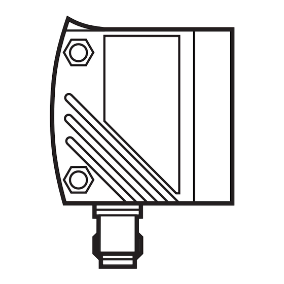
Sommaire des Matières pour IFM Electronic efector duolis O2D200
- Page 1 Montageanleitung Installation instructions Notice de montage Kontursensor Contour sensor Détecteur de contour...
-
Page 2: Bestimmungsgemäße Verwendung
Bestimmungsgemäße Verwendung Der Kontursensor erfasst im Durchlichtverfahren das Konturbild eines Prüfteils und vergleicht dieses mit den Konturen eines Referenzbildes. In Abhängigkeit vom Grad der Übereinstimmung wird das Prüfteil als Gut- oder Schlechtteil klassifiziert. Arbeitsabstand L Bei der Auswahl des Arbeitsabstandes ist zu berücksichtigen, daß die relevante Kontur bzw. -
Page 3: Montage
Montage Beleuchtungselement Meßobjekt Fokuseinsteller Die in der Abbildung gezeigte Montage können Sie mit dem Monta- gezubehör E2D101 und dem Beleuchtungselement (z. B. O2D900) erstellen. Hinweis Eine ausführliche Bedienungsanleitung finden Sie auf der CD-ROM für die Bediensoftware E2D102 oder im Internet. -
Page 4: Elektrischer Anschluß
Elektrischer Anschluß Prozeßanschluß M12, 8-pol. Externe 1 - U+ Beleuchtung 2 - Triggereingang 3 - 0V 4 - Triggerausgang für externe Beleuchtung 5 - Ready 6 - OUT 7 - IN 0 8 - IN 1 Steuerung z.B. SPS Hinweis: Adernfarben am Prozessanschluss entsprechen der Kabeldose E11231. Wird der Sensor intern getriggert, so ist der violette Anschluß... - Page 5 Timingdiagramm Ein-Ausgänge Triggerung auf positiver Flanke Trigger- eingang OUT gültig Ausgang READY OUT ungültig Ausgang Die Auswertezeit t ist je nach gewähltem Bildausschnitt und der Anzahl der Konturen unterschiedlich. Typische Auswertezeiten: 80...150 ms (ohne Verbindung zum Bedienprogramm) 1...2 s (mit Verbindung zum Bedienprogramm) Wechsel der Konfigurationsdatei Schalt...
-
Page 6: [Nm] 880 660 880 660 880 660
Verfügbare Beleuchtungselemente Beleuchtung Infrarot Rotlicht Infrarot Rotlicht Infrarot Rotlicht [nm] Bestell-Nr. O2D901 O2D900 O2D903 O2D902 O2D905 O2D904 Leuchtbereich [mm] 25 x 25 50 x 50 100 x 100 Maße [mm] 33,4 x 66,5 x 9,2 81 x 102 x 9,2 133 x 156 x 9,2 Anschlußschema 1 = Trigger... -
Page 7: Function And Features
Function and features The contour sensor uses backlight to compare the contours on an object with reference contours. Depending on the degree of mat- ching the test object is classified as being a good object or a bad object. Operating distance L When selecting the operating distance it has to be taken into account that the relevant contour or the relevant contour areas should cover approx. - Page 8 Installation backlight object to be measured focus setting The illustration shows mounting by means of the mounting accessory E2D101 and the backlight (e.g. O2D900). Note You will find detailed operating instructions on the CD ROM for the operating software E2D102 or on the ifm website.
-
Page 9: Electrical Connection
Electrical connection process connection M12, 8-pole external 1 - U+ lighting 2 - trigger input 3 - 0V 4 - trigger output for external lighting 5 - Ready 6 - OUT 7 - IN 0 8 - IN 1 controller, e.g. plc Note: Core colours of the process connection correspond to the socket E11231. - Page 10 Timing diagram inputs/outputs triggering on positive edge trigger input OUT ready output READY OUT not ready output not OK The evaluation time t differs depending on the selected image section and the number of contours. Typical evaluation times: 80...150 ms (without connection to the operating program) 1...2 s (with connection to the operating program) change of the configuration file...
-
Page 11: Dimensions [Mm] 33,4 X 66
Available backlights Lighting Infrared Red light Infrared Red light Infrared Red light [nm] Order no. O2D901 O2D900 O2D903 O2D902 O2D905 O2D904 Illuminated area [mm] 25 x 25 50 x 50 100 x 100 Dimensions [mm] 33.4 x 66.5 x 9.2 81 x 102 x 9.2 133 x 156 x 9.2 Wiring diagram... -
Page 12: Fonctionnement Et Caractéristiques
Fonctionnement et caractéristiques Le détecteur de contour à l'aide d'une lumière backlight compare le contour d'un objet avec le contour de référence mémorisé. En fonction du degré de similitude, l'objet contrôlé est classifié comme pièce bonne ou pièce mauvaise. Portée de travail L En sélectionnant la portée de travail il faut prendre en considération que le contour à... - Page 13 Montage lumière backlight objet à mesurer réglage de la focale Pour le montage montré dans l'illustration utiliser l'accessoire E2D101 et la lumière backlight (par ex. O2D900). Remarque Une notice de montage détaillée se trouve sur le CD ROM du logiciel E2D102 ou sur internet.
-
Page 14: Raccordement Électrique
Raccordement électrique connecteur process M12, 8 pôles lumière 1 - U+ backlight 2 - entrée trigger 3 - 0V 4 - sortie trigger pour éclairage externe 5 - Ready 6 - OUT 7 - IN 0 8 - IN 1 système de com- mande, par ex. -
Page 15: Diagramme De Temps Des Entrées/Sorties
Diagramme de temps des entrées/sorties trigger sur le front positif entrée trigger OUT prêt sortie READY OUT non prêt sortie pas OK Le temps d'évaluation t varie selon la section d'image sélectionnée et le nombre de contours. Temps d'évaluation typiques: 80 ... -
Page 16: Table Des Matières
Lumières backlight disponibles Eclairage Infrarouge Lumière rouge Infrarouge Lumière rouge Infrarouge Lumière rouge [nm] de commande O2D901 O2D900 O2D903 O2D902 O2D905 O2D904 Zone d'éclairage [mm] 25 x 25 50 x 50 100 x 100 Dimensions [mm] 33,4 x 66,5 x 9,2 81 x 102 x 9,2 133 x 156 x 9,2 Schéma de...


