
Manuels Connexes pour ROSIERES TC 04


Sommaire des Matières pour ROSIERES TC 04
- Page 1 NOTICE D'EMPLOI ET D'INSTALLATION DE LA TABLE DE CUISSON ELECTRIQUE INSTRUCTION FOR THE INSTALLATION AND OPERATION OF THE ELECTRIC HOB TC 04...
-
Page 2: Table Des Matières
SOMMAIRE Déballage de l'appareil ................3 Recommandations ................3 • INSTALLATION Consignes d'installation ................. 4 Raccordement électrique ..............5 / 6 Encastrement de la table de cuisson ..........7 / 8 • UTILISATION Présentation de la table de cuisson ............9 Fiche technique .................. -
Page 3: Déballage De L'appareil
DEBALLAGE DE L'APPAREIL Lors du déballage de la table de cuisson, vous trouverez un sachet constitué de pattes de fixation pour immobiliser la table sur le plan de travail. RECOMMANDATIONS LIRE ATTENTIVEMENT LA NOTICE POUR VOUS PERMETTRE DE TIRER LE MEILLEUR PARTI DE VOTRE APPAREIL. -
Page 4: Installation
éventuelles qui pourraient survenir lors de l'usage d'un appareil non relié à la terre, ou relié à une terre dont la continuité serait défectueuse. La table "TC 04" est équipée d'un câble d'alimentation* de type H05RR-F d'une section 3G2,5 mm², pour un raccordement Monophasé 220-240 V~ ou biphasé 220- 240 V2~. - Page 5 Pour procéder à un nouveau raccordement, il est impératif de respecter les consignes citées ci-contre. • Tout d'abord, vérifier que l'installation est protégée par un fusible approprié, voir tableau page 6, et que l'installation comporte des fils d'une section suffisante pour alimenter normalement l'appareil.
- Page 6 INSTALLATION: "LE RACCORDEMENT ELECTRIQUE" i g i é s é s é s é s ² ² ² ² 1 2 3 4 5 1 2 3 4 5 1 2 3 4 5 1 2 3 4 5 à PH PH PH PH PH t é...
- Page 7 INSTALLATION: "ENCASTREMENT" Le meuble ou le support dans lequel doit être encastrée la table, ainsi que les parois du meuble qui pourraient juxtaposer celui-ci, doivent être d'une matière résistant à une température élevée. De plus, il est nécessaire que le revêtement qui recouvre le meuble ou le support soit fixé...
- Page 8 INSTALLATION: "ENCASTREMENT" Le caisson de la table est équipé en dessous de 4 emplacements prévus pour recevoir les brides de fixation destinées à l'immobilisation de la table sur le meuble. Placer les 4 brides de fixation de manière à ce que la table de travail soit parfaitement plaquée au meuble support.
-
Page 9: Fiche Technique
6 kW Toutes ces caractéristiques sont données à titre indicatif. Soucieux de toujours améliorer la qualité de sa production, ROSIERES pourra apporter à ses appareils des modifications liées à l'évolution technique en respectant les conditions fixées à l'article R 132-2 du Code de la Consommation. -
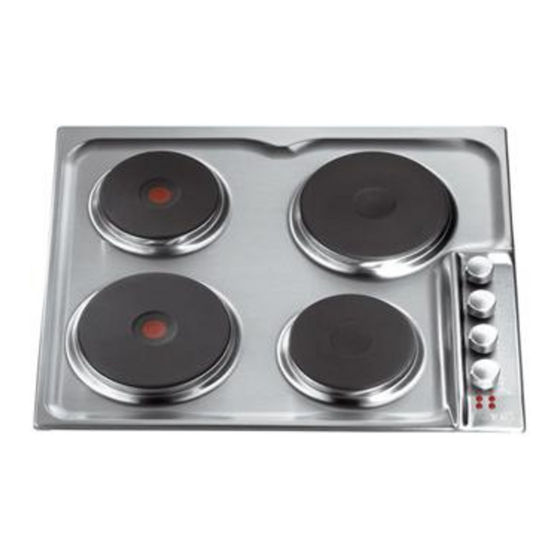
Page 10: La Plaque Électrique
LA PLAQUE ELECTRIQUE LA PLAQUE ELECTRIQUE STANDARD est commandée par un commutateur 7 positions. Chaque position correspond à une température permanente et progressive suivant le repère 1, 2, 3, 4, 5 et 6. LA PLAQUE ELECTRIQUE RAPIDE AUTO-PROTÉGÉE (avec point rouge) est commandée par un commutateur 7 positions. -
Page 11: Conseils D'utilisation Pour Cuisiner À L'électricité
A titre indicatif, nous vous communiquons ci-dessous selon le type de plaque électrique et le positionnement de la manette les différentes puissances obtenues : 0 0 0 0 0 1 1 1 1 1 2 2 2 2 2 3 3 3 3 3 4 4 4 4 4 5 5 5 5 5 6 6 6 6 6... -
Page 12: Entretien
ENTRETIEN Avant toute opération de nettoyage ou de démontage, il est impératif : . de déconnecter la table de cuisson de l'alimentation électrique. . d'attendre le refroidissement complet de la table. Ne jamais utiliser : . de produits abrasifs, d'éponges métalliques ou d'objets tranchants pour nettoyer la table. - Page 13 CONTENTS Unpacking the appliance ..............1 4 Recommendations ................1 4 • INSTALLATION Safety instructions ................1 5 Electrical connection ..............1 5 / 1 7 Fitting the hob ................1 8 / 1 9 • USING THE APPLIANCE Presentation of the hob ............... 2 0 Technical data ..................
-
Page 14: Unpacking The Appliance
UNPACKING THE APPLIANCE Inside the appliance you will find a plastic bag containing the fixing brackets to install the hob in the worktop. RECOMMENDATIONS PLEASE READ THE FOLLOWING CAREFULLY IN ORDER TO GET THE BEST FROM YOUR APPLIANCE. Please keep the operating and installation instructions in a safe place for future reference. Before fixing the hob, note the serial number of the appliance just in case you may require repairs from after sales service organisation. -
Page 15: Installation
• Any queries regarding the power supply cord should be referred to After Sales Service or a qualified technician. The hob "TC 04" is equipped with a supply cord type H05RR-F - area 3G2,5 mm² This power cord enables you to connect to exclusively single phase 220-240 V~ or two phase 220-240 V2~. - Page 16 To proceed to the new connection, you mus adhere the following instructions • Before making the connection, make sure that the installation is protected by a suitable fuse, see table on next page, and that it is fitted with wires of a large enough section to supply the appliance normally.
- Page 17 INSTALLATION: "ELECTRICAL CONNECTION" ² ² ² ² 1 2 3 4 5 1 2 3 4 5 1 2 3 4 5 1 2 3 4 5 PH PH PH PH PH 1rst Phase 1rst Phase 1rst Phase 1rst Phase Shunt 2nd Phase Shunt...
- Page 18 INSTALLATION: "BUILDING-IN" Both the unit into which the hob will be fitted and any adjacent kitchen furniture must be made from heat resistant material and fixed with heat resistant adhesive. If, when installing the hob, the lower part of the casing is adjacent to an area normally accessible when handling or cleaning, fit a heatproof partition 1 cm below the base of the casing, with a 10 x 10 cm opening in the rear right-hand corner, to avoid any risk of burning or damage.
- Page 19 INSTALLATION: "BUILDING-IN" The body of the hob is fitted with 4 location holes to take the fixing brackets that secure the intended to fix the hob in the unit. Place the 4 fixing brackets in such a way that the hob surface is placed perfectly in the support unit.
-
Page 20: Technical Data
Building-in dimensions (cm) - (see chapter "Installation") Width : 56 Depth : Total electrical power : 6 kW In order to improve the quality of the products, ROSIERES may carry out modifications linked to technical improvements. Appliance meeting with the standard CEE 89/336, and 73/23. -
Page 21: The Hot Plate
THE HOT PLATE THE STANDARD ELECTRICAL HOT PLATE This is a cast-iron hot plate, controlled by a 7 position switch. Each position corresponds to a permanent and progressive temperature according to the marks 1, 2, 3, 4, 5 and 6. RAPID SELF-PROTECTING ELECTRIC HOT PLATE (with a red dot in the centre) This is a cast-iron hot plate, controlled by a 7 position switch. - Page 22 For information, we note below the different powers reached according to the type of the plate and the control knob setting. 0 0 0 0 0 1 1 1 1 1 2 2 2 2 2 3 3 3 3 3 4 4 4 4 4 5 5 5 5 5 6 6 6 6 6...
- Page 23 MAINTENANCE Before all cleaning or dismantling operation, it is imperative to : . disconnect the hob to the mains supply. . let all parts of the hob cool down. Never use : . harsh abrasives, scouring pads or sharp object to clean the hob. •...
- Page 24 SA DES USINES DE ROSIERES - 30, rue Y. Lacelle - Rosières - 18400 LUNERY RCS Bourges B 553 720 053 - Capital de 18 000 000 F Tél. 02.48.55.78.00 - Télex 780868F - Fax 02.48.68.01.75...