Publicité
Les langues disponibles
Les langues disponibles
Liens rapides
–
OPERATION
INSTALLATION
& MAINTENANCE
MANUAL
–
SINGLE SPLIT INVERTER SERIES
INDOOR UNITS
MODELS
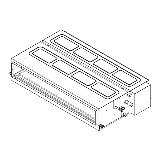
MEDIUM ESP DUCTED TYPE
PPIM-B09UFA1DQ
PPIM-B12UFA1DQ
PPIM-B18UFA1DQ
PPIM-B24UFA1DQ
PPIM-B30UFA1DQ
PPIM-B36UFA1DQ
PPIM-B48UFA1DQ
EN OPERATION INSTALLATION AND MAINTENANCE MANUAL
Original Instructions
FR MANUEL D'UTILISATION, D'INSTALLATION & D'ENTRETIEN
P02212Q
Scan the code to get the electronic manual.
Publicité

Manuels Connexes pour Hitachi AIR CORE 700 PPIM-B09UFA1DQ


Sommaire des Matières pour Hitachi AIR CORE 700 PPIM-B09UFA1DQ
- Page 1 – OPERATION INSTALLATION & MAINTENANCE MANUAL – SINGLE SPLIT INVERTER SERIES INDOOR UNITS MODELS MEDIUM ESP DUCTED TYPE PPIM-B09UFA1DQ PPIM-B12UFA1DQ PPIM-B18UFA1DQ PPIM-B24UFA1DQ PPIM-B30UFA1DQ PPIM-B36UFA1DQ PPIM-B48UFA1DQ Scan the code to get the electronic manual. EN OPERATION INSTALLATION AND MAINTENANCE MANUAL Original Instructions FR MANUEL D'UTILISATION, D'INSTALLATION &...
- Page 2 In case of any questions, please contact the designated dealer or service center. • For environmental benefit, please do not discard this product. Hitachi provides replaceable parts as • per relevant national and local laws, regulations and standard requirements.
- Page 3 DANGER Before reading the installation manual, please do not conduct installation works such as connections • of refrigerant piping, condensate pipes and wiring. Any violation may lead to system leakage, electrical failure or fire. Do not pour water into the indoor/outdoor unit. This product contains electrical components and if wet, •...
- Page 4 suitable for the same refrigerant. This unit <PPIM-UFA1DQ> is a PARTIAL UNIT AIR CONDITIONER, complying with PARTIAL UNIT • requirements of UL 60335-2-40/CSA C22.2 No. 60335-2-40, and must only be connected to other units that have been confirmed as complying to corresponding PARTIAL UNIT requirements of UL 60335-2- 40/CSA C22.2 No.
- Page 5 (c) Near machinery emitting electromagnetic waves. Electromagnetic waves may disturb the operation of the control system and cause the unit to malfunction. (d) Where flammable gas may leak, where there is carbon fiber, or ignitable dust suspension in the air, or where volatile flammables such as thinner or gasoline are handled.
- Page 6 Precautions for R32 This air conditioner uses R32 flammable refrigerant. Air conditioner with R32 refrigerant, if not be treated carefully, may cause serious harm to the human body or surrounding things. Please read the following instructions carefully before installing, using and maintaining. WARNING Do not use means to accelerate the defrosting process or to clean, other than those recommended by •...
- Page 7 Ensure no following objects under the indoor unit: • ○ Microwaves, ovens and other hot objects. ○ Computers and other high electrostatic appliances. ○ Sockets that plug frequently. Installation, maintenance, service, repairing, removing and disposal operations, shall only be • performed by the qualified personnel or recommended by the manufacturer.
- Page 8 specification. At all times the maintenance and service guidelines of this manual shall be followed. If in doubt, consult the manufacturer’s technical department for assistance. The following checks shall be applied to installations using R32: ○ The refrigerant charge is in accordance with the room size within which the refrigerant containing parts are installed.
- Page 9 Purging of the refrigerant circuit shall be achieved by breaking the vacuum in the system with inert gas • and continuing to fill until the working pressure is achieved, then venting to atmosphere, and finally pulling down to a vacuum. This process shall be repeated until no refrigerant is within the system. The system shall be vented down to atmospheric pressure to enable work to take place.
- Page 10 manufacturer if in doubt. In addition, a set of calibrated weighing scales shall be available and in good working order. Hoses shall be complete with leak-free disconnect couplings and in good condition. The recovered refrigerant shall be processed according to local legislation in the correct recovery •...
- Page 11 The standard operation procedure of the unit is explained in this manual. In case of any problem, please contact local dealer. Hitachi shall not be liable for defects arising due to alterations made by the customer without Hitachi’s consent in a written form.
- Page 12 Table of Contents Operation Manual 1. Safety Summary .............................1 2. Introduction to Units ............................1 3. Component Name ............................1 3.1 Indoor Unit ...............................1 3.2 Wired remote controller or Wireless Controller ..................1 4. Before Operation ............................2 5. Operation Method ............................2 6. Automatic Control ............................2 7.
- Page 13 1. Safety Summary Operation Manual 1. Safety Summary DANGER Preventing water into indoor/outdoor unit , otherwise the water may lead to short circuit. • Do not tamper with or adjust safety devices inside the indoor/outdoor unit as it may cause serious accidents. •...
- Page 14 4. Before Operation 4. Before Operation CAUTION Supply electrical power to the system for approximately 12 hours before start-up after long shut down. • Do not start the system immediately after power supply, it may cause a compressor failure, because the compressor is not heated well.
- Page 15 7. Filter Cleaning 7. Filter Cleaning Turn off the main power switch before taking out the filter. The indication, “ ” is shown on the display of the wired remote controller after passing the time set on the wired remote controller. (Default Setting Time of PPIM: 1,200 hours) After cleaning the air filter, perform filter sign reset according to the chapter of the wired remote controller CIW03-H.
- Page 16 1. Safety Summary Installation and Maintenance Manual 1. Safety Summary WARNING Do not conduct installation works such as connections of refrigerant piping, condensate pipes and • wiring before reading the installation manual. Ensure that the grounding wires are connected properly and firmly. •...
- Page 17 4. Indoor Unit Installation NOTICE Do not place anything on the unit. • 3.2 Handling of the Indoor Unit WARNING Before the installation and commissioning, do not place any irrelevant materials inside the indoor • unit and ensure there are no sundries in the indoor unit as it may lead to fire or accident. NOTICE During handling, do not damage the thermal insulation materials on the surface of the unit.
- Page 18 4. Indoor Unit Installation 4.2 Initial Inspection Install the indoor unit in a place that facilitates operation and maintenance as shown in figure 4.1. • Model: 9000~30000 Btu/h Model: 36000~48000 Btu/h [Unit: in. (mm)] Electrical cabinet 3-15/16(100) Electrical cabinet ≥ 39-3/8(1000) Maintenance openings ≥...
- Page 19 4. Indoor Unit Installation 4.3.2 Position of Hanging Bolt and Pipe Connection 1. This indicates the position of hanging bolt, connecting position of the refrigerant pipe as well as that of the condensate pipe. 2. Installation size is shown in figure 4.3. [Unit: in.
- Page 20 4. Indoor Unit Installation Stand bar (2) Indoor unit installation Suspension bolts * As shown in the following figure, Stand bar install the left bracket into nut and gasket of hanging bolt. * After ensuring that the left bracket Nuts and is correctly installed on the nut and Indoor unit Washers...
- Page 21 4. Indoor Unit Installation CAUTION If a lower sound level is further required, install silencer (field-supplied). • Design duct arrangement as “Unit External Static Pressure=Pressure Drop of Duct+Pressure Drop of • Air Outlet and Air Inlet”. If duct design is not appropriate, big sound and splash will occur. Before unit starting up, ensure the setting ESP is almost same with field duct pressure.
- Page 22 5. Refrigerant Piping Work 5. Refrigerant Piping Work DANGER Use only R32 refrigerant. During leakage and air tight test, no oxygen, acetylene, flammable or • poisonous gases must be charged, as these gases may cause explosion. It is recommended to use dry nitrogen for test.
- Page 23 5. Refrigerant Piping Work Perform the flaring work as shown below. [Unit: in. (mm)] º º Diameter -1/64 -0.4 Ød ΦA 1/4 (6.35) 11/32 (9.1) 0.02~0.03(0.4~0.8)R 3/8 (9.53) 1/2 (13.2) 1/2 (12.7) 10/16 (16.6) Φd 5/8 (15.88) 3/4 (19.7) Figure 5.3 Flaring Processing 2.
- Page 24 6. Drain Piping Unit: in(mm) Fixed Plate Refrigerant Pipe (≥15-3/4(400)) 4. Discharge and charge the refrigerant pipelines by following the Installation and Maintenance Manual of the outdoor unit. NOTICE Excessive or insufficient refrigerant is the major reason for system abnormalities. Please fill in the •...
- Page 25 7. Electrical Wiring NOTICE When the relative humidity of inlet or ambient air exceeds 80%, apply an (field-supplied) auxiliary • drain pan beneath the indoor unit as shown in Fig.6.2. Indoor Unit Auxiliary Drain Pan (Field-Supplied) To the Atmosphere Figure 6.2 Auxiliary Drain Pan NOTICE Install the condensate pipe at a downward slope, as the condensate water may flow backwards and •...
- Page 26 7. Electrical Wiring M5: 1.5 to 1.8 lbf.ft (2.0 to 2.4 N·m) M6: 3.0 to 3.7 lbf.ft (4.0 to 5.0 N·m) M8: 6.6 to 8.1 lbf.ft (9.0 to 11.0 N·m) M10: 13.3 to 17.0 lbf.ft (18.0 to 23.0 N·m) Connect earth wires for the outdoor / indoor unit to prevent an electrical shock or an unexpected •...
- Page 27 7. Electrical Wiring 7.2 Field Minimum Wire Sizes for Power Source Use an ELB (Earth Leakage Breaker). If it is not used, it will cause an electric shock or a fire. • Do not operate the system until all the check points have been cleared. •...
- Page 28 7. Electrical Wiring Example for Electrical Wiring Connection The transmission cable length between the outdoor unit and the indoor unit shall be less than 246ft(75m). Wired Remote Controller Cable (Field-Supplied) Shielded Twist Pair Cable O.U Power Supply I.U Power Supply [18AWG(0.75mm )] This cable does not need any polarity.
- Page 29 7. Electrical Wiring and size complying with local code are used for intermediate wiring between the outdoor unit and the indoor units to prevent noise obstacle. (5) When the standard wire is used for field-wiring connection, the M4 and M5 crimping terminal should be used.
- Page 30 7. Electrical Wiring NOTE: The ring core needs to be installed on the transmission cable between the fixed wire clamp and • TB2, where additional insulation rubber is peeled off. [Procedure] Insert the transmission cable into the ring core as shown in the figure below before connecting to the terminal board.
- Page 31 7. Electrical Wiring 5. Capacity code setting (DSW3) No setting is required as these have been preset at the factory at time of production. These switches have been set according to the capacity of the indoor unit. DSW3 6. Unit type code setting (DSW4) As this is already set before shipment, no setting is required.
- Page 32 8. Test Run NOTICE The "■" mark indicates the positions of DIP switches. The figures show settings before shipment. • When the unit no. and the refrigerant cycle no. are set, record them to facilitate maintenance and • servicing activities in the future. Turn OFF all the power supplies of the indoor and outdoor units before DIP switch setting.
- Page 33 Pour toute question, veuillez contacter le revendeur ou le centre de service désigné. • Dans un souci de protection de l'environnement, veuillez ne pas mettre ce produit au rebut. Hitachi fournit • des pièces remplaçables conformément aux lois, réglementations et normes nationales et locales en vigueur.
- Page 34 DANGER Avant de lire le manuel d'installation, n'effectuez pas de travaux d'installation tels que les raccordements • de la tuyauterie du réfrigérant, des tuyaux de condensat et du câblage. Toute négligence peut entraîner une fuite du système, une défaillance électrique ou un incendie. Ne versez pas d'eau dans l'unité...
- Page 35 Cette unité <PPIM-UFA1DQ> est un CLIMATISATEUR PARTIEL, elle ne doit être raccordée qu'à un appareil • compatible avec le même fluide frigorigène. Cette unité <PPIM-UFA1DQ> est un CLIMATISATEUR PARTIEL, conforme aux exigences UL 60335-2-40/ • CSA C22.2 No. 60335-2-40, et ne doit être connectée qu'à d'autres unités qui ont été confirmées comme étant conformes aux exigences UL 60335-2-40/CSA C22.2 No.
- Page 36 d'huile, par exemple, dans une cuisine: les composants en plastique risquent de se détériorer et de tomber ou de provoquer des fuites d'eau. (b) En cas de production de gaz corrosif, tel que l'acide sulfureux, la corrosion des tuyaux en cuivre ou des pièces soudées peut provoquer des fuites de réfrigérant.
- Page 37 Précautions à prendre pour le R32 Ce climatiseur utilise le réfrigérant inflammable R32. Le climatiseur contenant du réfrigérant R32, s'il n'est pas manipulé avec précaution, peut causer de graves dommages au corps humain ou aux objets environnants. Veuillez lire attentivement les instructions suivantes avant l'installation, l'utilisation et l'entretien. AVERTISSEMENT N'utilisez pas d'autres moyens que ceux recommandés par le fabricant pour accélérer le processus de •...
- Page 38 ○ Les prises de courant auxquelles on se connecte fréquemment. Les opérations d'installation, de maintenance, d'entretien, de réparation, de démontage et • d'élimination ne doivent être effectuées que par du personnel qualifié ou recommandé par le fabricant. Toute procédure de travail qui concerne les moyens de sécurité ne doit être exécutée que par des •...
- Page 39 ○ Les machines de ventilation et les entrées et sorties doivent fonctionner correctement et ne pas être obstruées ; elles doivent être maintenues à l'écart des sources de chaleur et des conditions inflammables ou explosives. ○ Le marquage de l'équipement doit rester visible et lisible. Les marquages et les panneaux illisibles doivent être corrigés.
- Page 40 La purge du circuit frigorifique doit être réalisée en supprimant le vide dans le système avec un gaz • inerte et en continuant à remplir jusqu'à ce que la pression de service soit atteinte, puis en ventilant dans l'atmosphère et enfin en tirant vers le bas jusqu'à ce que le vide soit atteint. Ce processus doit être répété...
- Page 41 L'équipement de récupération doit être en bon état de fonctionnement, accompagné d'un ensemble • d'instructions concernant l'équipement disponible et adapté à la récupération du réfrigérant inflammable. En cas de doute, consulter le fabricant. En outre, il convient de disposer d'un jeu de balances étalonnées et en bon état de fonctionnement.
- Page 42 La procédure d'utilisation standard de l'appareil est expliquée dans ce manuel. En cas de problème, veuillez contacter votre revendeur local. Hitachi n'est pas responsable des défauts résultant de modifications apportées par le client sans l'accord écrit de Hitachi.
- Page 43 Table des matières Manuel d'utilisation 1. Résumé de sécurité ............................1 2. Présentation des unités ..........................1 3. Nom des composants .............................1 3.1 Unité intérieure ............................1 3.2 Télécommande filaire ou sans fil......................1 4. Avant l'utilisation ............................2 5. Méthode de fonctionnement .........................2 6. Contrôle automatique ............................2 7.
- Page 44 1. Résumé de sécurité Manuel d'utilisation 1. Résumé de sécurité DANGER Empêcher l'eau de pénétrer dans l'unité intérieure/extérieure, car l'eau pourrait provoquer un court-circuit. • Ne pas manipuler ou régler les dispositifs de sécurité à l'intérieur de l'unité intérieure/extérieure, car cela •...
- Page 45 4. Avant l'utilisation 4. Avant l'utilisation ATTENTION L'alimentation électrique du système doit être assurée pendant environ 12 heures avant la mise en service • après un arrêt prolongé. Ne mettez pas le système en marche immédiatement après l'avoir alimenté en électricité, car cela pourrait entraîner une panne du compresseur, celui-ci n'étant pas bien chauffé.
- Page 46 7. Nettoyage du filtre 7. Nettoyage du filtre Eteignez l'interrupteur principal avant de retirer le filtre. ” s'affiche sur l'écran de la télécommande filaire après l'écoulement de la durée réglée L'indication, “ sur la télécommande filaire. (Temps de réglage par défaut de l'PPIM : 1 200 heures) Après avoir nettoyé...
- Page 47 1. Résumé de sécurité Manuel d'installation et d'entretien 1. Résumé de sécurité AVERTISSEMENT N'effectuez pas de travaux d'installation tels que les raccordements de la tuyauterie de réfrigérant, des • tuyaux de condensat et du câblage avant d'avoir lu le manuel d'installation. Veillez à...
- Page 48 4. Installation de l'unité intérieure 3.2 Manipulation de l'unité intérieure AVERTISSEMENT Avant l'installation et la mise en service, ne placez pas de matériaux inutiles à l'intérieur de l'unité • intérieure et veillez à ce qu'il n'y ait pas de produits indésirables dans l'unité intérieure afin d'éviter tout risque d'incendie ou d'accident.
- Page 49 4. Installation de l'unité intérieure 4.2 Inspection initiale Installez l'unité intérieure dans un endroit qui facilite l'utilisation et l'entretien, comme indiqué sur la figure 4.1. • Modèle: 9000~30000 Btu/h Modèle: 36000~48000 Btu/h [Unité: in. (mm)] Armoire d'électricité Ouvertures de 3-15/16(100) Armoire d'électricité...
- Page 50 4. Installation de l'unité intérieure 4.3.2 Position des boulon de suspension et du raccord de tuyauterie 1. La position des boulons de suspension, la position de raccordement des tuyaux de réfrigérant et celle du tuyau de condensat sont indiquées. 2. Les dimensions de l'installation sont indiquées dans la figure 4.3 de la page suivante. [Unité: in.
- Page 51 4. Installation de l'unité intérieure (2) Installation de l'unité intérieure Barre d'appui Boulons de suspension * Comme le montre la figure suivante, Barre d'appui installez le support gauche dans l'écrou et dans le joint du boulon d'accrochage. * Après s'être assuré que le support gauche Écrous et est correctement installé...
- Page 52 4. Installation de l'unité intérieure ATTENTION Si vous souhaitez obtenir un niveau sonore plus faible, installez un silencieux (fourni par le fabricant). • La conception des conduits doit être comme suit: "Pression statique externe de l'unité = chute de • pression du conduit + chute de pression de la sortie d'air et de l'entrée d'air".
- Page 53 5. Travaux concernant la tuyauterie de réfrigérant 5. Travaux concernant la tuyauterie de réfrigérant DANGER Utilisez uniquement le réfrigérant R32. Pendant les essais d'étanchéité, il ne faut pas charger d'oxygène, • d'acétylène, de gaz inflammables ou de gaz toxiques, car ces gaz peuvent provoquer des explosions. Pour les essais, il est recommandé...
- Page 54 5. Travaux concernant la tuyauterie de réfrigérant Effectuer le travail consistant à évaser comme indiqué ci-dessous. [Unité: in. (mm)] º º Diamètre -1/64 -0,4 Ød ΦA 1/4 (6,35) 11/32 (9,1) 3/8 (9,53) 1/2 (13,2) 0,02~0,03(0,4~0,8)R 1/2 (12,7) 10/16 (16,6) 5/8 (15,88) 3/4 (19,7) Φd Figure 5.3 Traitement de l'évasement...
- Page 55 6. Tuyauterie de vidange Unité: in. (mm) Plaque fixe Tuyau de réfrigérant (≥15-3/4(400)) 4. Vidangez et chargez les conduites de réfrigérant en suivant les instructions du manuel d'installation et d'entretien de l'unité extérieure. AVIS L'excès ou l'insuffisance de réfrigérant est la principale cause des anomalies du système. •...
- Page 56 7. Câblage électrique AVIS Lorsque l'humidité relative de l'air entrant ou de l'air ambiant dépasse 80 %, placez un bac de • récupération supplémentaire (installé sur place) sous l'unité intérieure, comme illustré à la figure 6.2. Unité intérieure Bac de vidange auxiliaire (installé...
- Page 57 7. Câblage électrique M4: 0,7 to 1,0 lbf.ft (1,0 to 1,3 N·m) M5: 1,5 to 1,8 lbf.ft (2,0 to 2,4 N·m) M6: 3,0 to 3,7 lbf.ft (4,0 to 5,0 N·m) M8: 6,6 to 8,1 lbf.ft (9,0 to 11,0 N·m) M10: 13,3 to 17,0 lbf.ft (18,0 to 23,0 N·m) Raccordez les fils de mise à...
- Page 58 7. Câblage électrique pas faire fonctionner le système jusqu'à ce que la fuite électrique soit détectée et réparée. (b) Vérifiez que les vannes d'arrêt de l'unité extérieure sont complètement ouvertes, puis démarrez le système. Paramètres électriques et spécifications des câbles de l'unité intérieure Tension Spécifications Spécifications...
- Page 59 7. Câblage électrique Exemple de raccordement du câblage électrique La longueur du câble de transmission entre l'unité extérieure et l'unité intérieure doit être inférieure à 246 pieds (75m). Télécommande filaire Câble du contrôleur à distance (Fourni sur site) Alimentation O.U Alimentation I.U Câble blindé...
- Page 60 7. Câblage électrique et les unités intérieures afin d'éviter tout problème de bruit. (5) Lorsque du fil standard est utilisé pour la connexion du câblage sur site, les bornes à sertir M4 et M5 doivent être utilisées. Lorsqu'un seul fil est utilisé, donnez-lui la forme indiquée dans la figure ci-dessous et connectez-le pour serrer la rondelle uniformément.
- Page 61 7. Câblage électrique NOTE: Le noyau annulaire doit être installé sur le câble de transmission entre le serre-fil fixe et TB2, là où il • faut enlever le caoutchouc d'isolation supplémentaire. [Procédure] Insérez le câble de transmission dans le noyau de l’anneau comme indiqué dans la Bande figure ci-dessous avant de le connecter à...
- Page 62 7. Câblage électrique 6. Réglage du code du type d'unité (DSW4) Comme ce code est déjà réglé avant l'expédition, aucun réglage n'est nécessaire. Ce PPIM commutateur est utilisé pour régler le code de type d'unité qui correspond au type MARCHE de l'unité...
- Page 63 8. Essai de fonctionnement Coupez toutes les alimentations électriques des unités intérieure et extérieure avant de régler les • commutateurs DIP. Sinon, le réglage ne sera pas valide. 7.6 Réglage de la pression statique externe Le volume du flux d'air peut être modifié en fonction de la pression statique externe en réglant le code de l'élément sur "C5"...
- Page 64 1194984 Hitachi-Johnson Controls Air Conditioning, Inc. Specifications in this catalogue are subject to change without notice, in order that Hitachi-Johnson Controls may bring the latest innovations to customers. 2024.07...