Publicité
Liens rapides
DECLARATION OF CONFORMITY
This product is marked
2006/95/CE
– Low voltage no.
– Electromagnetic compatibility no. 89/336 ECC, 92/31 EEC
and 93/68 EEC.
This declaration will become void in case of misuse and/or non
observance though partial of manufacturer's installation and/or
operating instructions.
F-GAS Regulation (EC) No. 842/2006
Do not vent R410A into atmosphere: R410A is a fluorinated
greenhouse gas, covered by Kyoto Protocol, with a Global
Warming Potential (GWP) = 1975.
OPERATING LIMITS
L
Cooling Maximum conditions
Outdoor temperature : 43°C D.B.
Room temperature
: 32°C D.B. / 23°C W.B.
L
Cooling Minimum conditions
Outdoor temperature : 19°C D.B.
Room temperature
: 19°C D.B. / 14°C W.B.
L
Heating Maximum conditions
Outdoor temperature : 24°C D.B. / 18°C W.B.
Room temperature
: 27°C D.B.
L
Heating Minimum conditions
Outdoor temperature :
Room temperature
: 16°C D.B.
WARNING
Read the yellow instruction sheet attached to the outdoor
units.
PARTS
FIGURE
Raw plug *
Ricevitore con
cavo (5 mt.)
Remote
control
Remote control
unit holder
All manuals and user guides at all-guides.com
INSTALLATION INSTRUCTIONS
– Split system air conditioner –
This air conditioner uses the new refrigerant R410A.
as it satisfies Directives:
.
–15°C W.B.
ACCESSORIES SUPPLIED WITH THE UNIT
Q.TY
PARTS
AAA Alkaline
2
battery
Tapping
1
screw 4 x 30
Tapping
1
screw 3,5 x 13
1
37.4196.132.0
Model Combinations
Combine indoor and outdoor units only as listed below.
Indoor Units
SAP-URV96EH
SAP-URV126EH
SAP-URV186EH
SAP-URV246EH
FOR "MULTI SPLIT" INSTALLATION SEE "MULTI DC INVERTER
COMBINATIONS TABLE"
Power Supply:
220 - 240 V ~ 50 Hz
Tools required for installation (not supplied)
1. Standard screwdriver
2. Phillips head screwdriver
3. Knife or wire stripper
4. Tape measure
5. Level
6. Sabre saw or key hole saw
7. Hacksaw
8. Core bits ø 5
FIGURE
Q.TY
PARTS
Drain
2
elbow *
2
Drain cap *
Cushion
2
rubber *
©SANYO 2008
Outdoor Units
SAP-CRV96EH
SAP-CRV126EH
SAP-CRV186EH
SAP-CRV246EH
19. Hammer
10. Drill
11. Tube cutter
12. Tube flaring tool
13. Torque wrench
14. Adjustable wrench
15. Reamer (for reburring)
16. Hex. key
FIGURE
Q.TY
1
4
4
*
Packed in the outdoor unit.
EG
I
F
D
E
P
GR
Publicité

Manuels Connexes pour Sanyo URV96


Sommaire des Matières pour Sanyo URV96
- Page 1 Raw plug * battery elbow * Ricevitore con Tapping Drain cap * cavo (5 mt.) screw 4 x 30 Remote Tapping Cushion control screw 3,5 x 13 rubber * Packed in the outdoor unit. Remote control unit holder 37.4196.132.0 ©SANYO 2008...
- Page 2 All manuals and user guides at all-guides.com • Ground the unit following local electrical codes. IMPORTANT! Please read before installation • The Yellow/Green wire cannot be used for any connection different from the ground connection. • Connect all wiring tightly. Loose wiring may cause overheating This air conditioning system meets strict safety and operating at connection points and a possible fire hazard.
- Page 3 Deoxidized annealed copper tube for refrigerant tubing connecting the units of the system; it has to be insulated with foamed polyethylene (min. thickness 8mm). NARROW TUBE LARGE TUBE MODEL OUTER DIAMETER MIN. THICKNESS OUTER DIAMETER MIN. THICKNESS URV96/126 6,35 mm 0,8 mm 9,52 mm 0,8 mm URV186 6,35 mm 0,8 mm 12,7 mm...
- Page 4 FIGURA Batteria Curva Tassello alcalina AAA drenaggio * Vite Ricevitore con Tappo autofilettante cavo (5 mt.) drenaggio * 4 x 30 Vite Cuscinetto Telecomando autofilettante in gomma * 3,5 x 13 Imballato nell’unità esterna. Supporto del telecomando 37.4196.132.0 ©SANYO 2008...
- Page 5 All manuals and user guides at all-guides.com IMPORTANTE! • Eseguire la messa a terra dell’unità secondo le norme Leggere prima di iniziare l’installazione elettriche locali. • Il conduttore giallo/verde non può essere utilizzato per collegamenti diversi dalla messa a terra. Questo sistema di condizionamento deve seguire rigidi standard •...
- Page 6 Tubo in rame ricotto e disossidato per refrigerazione per il collegamento tra le unità, ed isolato con polietilene espanso di spessore min. 8 mm. TUBO PICCOLO TUBO GRANDE MODELLO DIAMETRO ESTERNO SPESSORE MINIMO DIAMETRO ESTERNO SPESSORE MINIMO URV96/126 6,35 mm 0,8 mm 9,52 mm 0,8 mm URV186 6,35 mm 0,8 mm 12,7 mm...
- Page 7 Coude de Cheville drainage * Groupe récepteur Couvercle de avec rallongede Vis 4 x 30 drainage * câble (5 mt.) Commande a Caoutchouc Vis 3,5 x 13 distance amortisseur * Emballées avec l’appareil extérieur. Berceau de télécommande 37.4196.132.0 ©SANYO 2008...
- Page 8 All manuals and user guides at all-guides.com • Effectuez la mise à la terre de l'appareil en respectant les IMPORTANT! Veuillez lire ce qui suit avant de commencer réglementations électriques locales. • Le câble jaune/vert ne peut en aucun cas être utilisé pour toute Ce système de conditionnement de l'air répond à...
- Page 9 Lignes en cuivre recuit et désoxydé pour réfrigération pour le raccordement entre les unités. La ligne doit être isolée en mousse de polyéthylène avec épaisseur min. de 8mm. TUYAU ETROIT TUYAU LARGE MODELE DIAMETRE EXTERIEUR EPAISSEUR MIN. DIAMETRE EXTERIEUR EPAISSEUR MIN. URV96/126 6,35 mm 0,8 mm 9,52 mm 0,8 mm URV186 6,35 mm 0,8 mm 12,7 mm...
- Page 10 TEILE ABBILDUNG MENGE Dübel Bogenrohr * Alkalibatterie Empfänger mit Selbst- Rohrver- schneidende verlängerungskabel Gewinde- schjuß * (5 mt.) schraube 4 x 30 Selbst- schneidende Fernbedienung Gummipolster * Gewinde- schraube 3,5 x 13 Beiliegend zum Außengerät. Fernbedienungs- Wandhalter 37.4196.132.0 ©SANYO 2008...
- Page 11 All manuals and user guides at all-guides.com WICHTIG! Verbindungen unzureichende Erdung können Bitte vor Arbeitsbeginn lesen Unfallverletzungen oder Tod verursachen. • Erden Sie das Gerät gemäß den örtlich zutreffenden Diese Klimaanlage entspricht strengen Sicherheits- und Vorschriften. Betriebsnormen. • Das Gelbe/Grüne Kabel ist für die ausschließliche Verwendung Für den Installateur oder Bediener dieser Anlage ist es wichtig, sie als Erdleitung.
- Page 12 MODELLE LIEFERUNG MENGE (g / m)* URV96 URV126 URV186/246 FUR INSTALLATION “MULTI SPLIT” SEHEN DIE INSTALLATIONSANLEITUNGEN DER AUSSENEINHEIT * Für jeden Meter mehr als die Standard Länge bei Lieferung, berechnen Sie zusätzliches Kühlmittel wie in der Tafel gezeigt ist. Ölzusatz im Kompressor ist nicht notwendig.
- Page 13 Gr. receptor Tapa autorroscante con cable (5 mt.) de drenaje * 4 x 30 Tornillo Mando a Goma autorroscante distancia amortiguadora * 3,5 x 13 Supporte de la Empacado en la unidad externa. unidad de control remoto 37.4196.132.0 ©SANYO 2008...
- Page 14 All manuals and user guides at all-guides.com • Realizar la puesta a tierra de la unidad siguiendo las normas ¡IMPORTANTE! Leer antes de empezar la instalación eléctricas locales. • El conductor amarillo/verde no se puede utilizar para conexiones que no sean la de tierra. Este sistema de acondicionamiento cumple medidas rígidas de •...
- Page 15 Tubo para refrigeración de cobre recocido y desoxidado, aislado con espuma de polietileno de 8 mm de espesor, para la conexión entre las unidades. TUYAU ETROIT TUYAU LARGE MODELE DIAMETRE EXTERIEUR EPAISSEUR MIN. DIAMETRE EXTERIEUR EPAISSEUR MIN. URV96/126 6,35 mm 0,8 mm 9,52 mm 0,8 mm URV186 6,35 mm 0,8 mm 12,7 mm...
- Page 16 Tampa de com cabo abrir roscas esgoto * (5 mt.) 4 x 30 Parafuso de Controle Borracha de abrir roscas remoto amortecimento * 3,5 x 13 Supporto do Na embalagem da unidade para montagem no exterior. controle remoto 37.4196.132.0 ©SANYO 2008...
- Page 17 All manuals and user guides at all-guides.com IMPORTANTE ! • Ligue a unidade à terra seguindo as normas locais de eletricidade. Queira ler antes de colocar a unidade em • O fio AMARELO/VERDE só deve ser usado para ligação à funcionamento terra.
- Page 18 Tubo de cobre recozido desoxidado para a tubagem do refrigerante para unir as unidades e isolado com espuma de polietileno cuja espessura da parede externa não deve ser inferior a 8mm. TUBO ESTREITO TUBO LARGO MODELO DIÂMETRO EXTERNO ESPESSURA MIN. DIÂMETRO EXTERNO ESPESSURA MIN. URV96/126 6,35 mm 0,8 mm 9,52 mm 0,8 mm URV186 6,35 mm 0,8 mm 12,7 mm...
- Page 19 ÚÔ¤ÎÙ·Û˘ (5Ì.) Monav d a BIDA Elastikov 3,5 x 13 thleceiristhriv o u maxilav r i * Qhv k h sugkrav t hsh Paketav r ontai me exwterikhv monav d a. Monav d a thleceiristhriv o u 37.4196.132.0 ©SANYO 2008...
- Page 20 All manuals and user guides at all-guides.com • Geiwv s te to suv s thma suv m fwna me tou" iscuv o nte" topikouv " SHMANTIKO ! hlektrikouv " ksnonismouv s . Diabav s te prin arciv s ete thn egkatav s tash •...
- Page 21 M M E E G G A A L L O O S S S S W W L L H H N N A A S S M M O O N N T T E E L L O O EXWTERIKH DIAMETROS ELACISTO PACOS ESWTERIKH DIAMETROS ELACISTO PACOS URV96/126 6,35 mm 0,8 mm 9,52 mm 0,8 mm URV186...
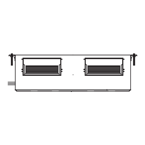
- Page 22 All manuals and user guides at all-guides.com INDOOR UNIT • UNITÁ INTERNA • UNITE INTERIEURE • INNENEINHEIT • UNIDAD INTERIOR • UNIDADE INTERIORE • ESWTERIKH MONADA URV96/126 1500 1100 URV186/246 1700 1100 Raumbedarf des Gerätes . Minimum operation and maintenance area.
- Page 23 All manuals and user guides at all-guides.com Drill a 80 mm diameter hole, for the passage of refrigeration pipework, condensate pipework and electrical cable. Insert a PVC pipe in the wall. Eseguire un foro da 80 mm per il passaggio dei tubi del refrigerante, scarico condensa e cavo elettrico.
- Page 24 All manuals and user guides at all-guides.com A unidade possui um tubo de PVC da bomba de descarga de condensação. A bomba tem uma prevalência de 250 mm além da unidade. Descarregar a condensação por queda com uma pendência mínima de 1:100. A altura máxima necessária no tubo de descarga de condensação deve ser atingida no primeiro trecho próximo à...
- Page 25 All manuals and user guides at all-guides.com Das elektrische Kabel für die Klemmbrett-Verbindung vorbereiten und sie verbinden. (Sieh elektrische Angaben). Das Kabel an der Drahtklemme befestigen. WARNUNG Stellen Sie sicher, daß alle Kabelverbindungen fest sind. Lose Kabel können zur Überhitzung des Anschlusses oder Fehlfunktion des Gerätes führen.
- Page 26 All manuals and user guides at all-guides.com Rear and front flange for the air intake. The value included in the brackets is referred to the model 186/246. Flangia anteriore e posteriore per la ripresa dell’aria. Il valore incluso tra parentesi è...
- Page 27 All manuals and user guides at all-guides.com DUCT FOR FRESH AIR • CONDOTTO PER ARIA ESTERNA DI RINNOVO • CONDUIT POUR LE RENOUVELLEMENT DE L’AIR • LEITUNG FÜR NEUE LUFT • CONDUCTO DE RICAMBIO DEL AIRE • CONDUTA DE RENOVAÇÃO DO AR • AGWGOS AERA ANANEWSHS There is a duct connection port for drawing in fresh air.
- Page 28 All manuals and user guides at all-guides.com CRV: OUTDOOR UNIT • CRV: UNITÁ ESTERNA • CRV: UNITE EXTERIEUR • CRV: AUßENEINHEIT • CRV: UNIDAD EXTERIOR • CRV: UNIDADE EXTERIOR • CRV: E E X X W W T T E E R R I I K K H H M M O O N N A A D D A A CMRV: SEE INSTALLATION INSTRUCTIONS OF OUTDOOR UNIT •...
- Page 29 All manuals and user guides at all-guides.com Remove the side access panel, then connect the power line and interconnecting wires to outdoor unit on the terminal strip and secure them with clamps. Rimuovere lo sportellino laterale, quindi collegare i fili elettrici di potenza e di collegamento all'unità...
- Page 30 All manuals and user guides at all-guides.com Lubricate A good flare has the following characteristics: - inside surface is glossy and smooth - edge is smooth - tapered sides are of uniform length. Apply refrigerant lubricant to the matching surface of the flare and union before connecting them together.
- Page 31 All manuals and user guides at all-guides.com Air purging of internal unit and refrigerant tubes. Connect the vacuum pump to the outside unit as shown in the figure. Air and moisture have undesiderable effects on the refrigerant system. Spurgo aria unità interna e tubi di collegamento. Collegare la pompa del vuoto all'unità...
- Page 32 All manuals and user guides at all-guides.com Turn the service valves stem in counterclockwise to fully open the valves. At this point vacuum pump flexible hose can be disconnected. Replace bonnet and flare nut, tighten them to 200 kg/cm with a torghe wrench. Aprire completamente le valvole di servizio (senso antiorario).
- Page 33 All manuals and user guides at all-guides.com The service port on the wide tube service valve uses a Schrader core valve to access the refrigerant system. Therefore, be sure to use a hose connector which has a push-pin inside. La valvola di servizio del rubinetto dell'unità esterna da utilizzare per il vuoto del sistema, ripristino carica refrigerante e misurazione della pressione di esercizio è...
- Page 34 All manuals and user guides at all-guides.com SYSTEM WIRING DIAGRAM • COLLEGAMENTI ELETTRICI DEL SISTEMA • BRANCHEMENTS ELECTRIQUES DU SYSTEME • ELEKTRISCHE ANSCHLÜSSE DES SYSTEMS • CONEXIONES ELECTRICAS DEL SISTEMA • SISTEMA DE INSTALAÇÃO ELÉTRICA • H H L L E E K K T T R R I I K K H H S S U U N N D D E E S S H H T T O O U U S S U U S S T T H H M M A A T T O O S S POWER SUPPLY 230-240 V - 50Hz A Power supply wiring length...
- Page 35 All manuals and user guides at all-guides.com Supply power wire A: Multipolar electric wire. Size and length of the suggested electric wire are showed on table “electrical data”. The wire must be Mod. H05VV-F (according to CEI 20-19 CENELEC HD 22). Make sure the length of the conductors between the fixing point and the terminals allows the straining of the conductors L, N before that of the grounding.
- Page 36 All manuals and user guides at all-guides.com Cable de alimentación A: Cable eléctrico multipolar; la sección y la longitud del cable eléctrico aconsejado están indicadas dentro de la tabla “Datos eléctricos”. El cable debe ser del tipo H05VV-F (según CEI 20-19 CENELEC HD22). Asegurarse de que la longitud de los conductores entre el punto de fijación del cable y el tablero de bornes es tal que los conductores activos se tiendan antes del conductor de puesta a tierra.
- Page 37 All manuals and user guides at all-guides.com TEST RUN • COME ESEGUIRE LA PROVA DEL CONDIZIONATORE (TEST RUN) • CONTROLE FINALE • ENDKONTROLLE • COMO REALIZAR LA PRUEBA DEL ACONDICIONADOR (TESTRUN) • COMO FAZER O TESTE DO APARELHO DE AR CONDICIONADO • PWS NA KANETE TH DOKIMH TOU KLIMATISTIKOU (TEST RUN) Switch on the power supply.
- Page 38 All manuals and user guides at all-guides.com REMOTE CONTROL UNIT INSTALLATION • POSIZIONE DI INSTALLAZIONE TELECOMANDO • EMPLACEMENT DE LA COMMANDE A DISTANCE • POSITION DER FERNBEDIENUNG • POSICION DE INSTALACION DEL MANDO A DISTANCIA • POSIÇÃO DA INSTALAÇÃO DA UNIDADE DE CONTROLE REMOTO • Q Q E E S S H H T T O O P P O O Q Q E E T T H H S S H H S S T T H H L L E E C C E E I I R R I I S S T T H H R R I I O O U U REMOTE CONTROL UNIT INSTALLATION The remote control unit may operated either from a non-fixed position or from a wall-mounted position.
- Page 39 All manuals and user guides at all-guides.com Rear side Press ON/OFF Hole for safety string Set in operation place HIGH POWER button Button 1HR. TIMER button (Reset) button WALL-MOUNTED • Momentarily place the remote control unit in the desired mounting position. •...
- Page 40 Address Setting of the Remote Control Unit The address can be set in order to prevent interference between remote controllers when two Sanyo indoor units are installed near each other. The address is normally set to “A.” To set a different address, it is necessary to change the address on the second remote controller.
- Page 41 Ajuste de la dirección de la unidad de control remoto La dirección puede ajustarse para evitar interferencias entre los mandos a distancia cuando se han instalado dos unidades interiores de Sanyo una cerca de la otra. La dirección se ajusta normalmente en “A”. Para ajustar otra dirección, es necesario cambiar la dirección del segundo controlador remoto.
- Page 42 All manuals and user guides at all-guides.com INFRARED RECEIVER INSTALLATION • INSTALLAZIONE RICEVITORE • INSTALLATION DU RÉCEPTEUR • EMPFÄNGER INSTALLATION • INSTALACIÓN DEL RECEPTOR • INSTALAÇÃO RECEPTOR • E°KATA™TA™H ¢EKTH Y¶EPY£P Slot a screwdriver by the 2 slits on the cover sides, and separate the cover from the base.
- Page 43 All manuals and user guides at all-guides.com Perform the earth connection with the terminal on the base, as provided. Complete earth connection and fasten the other end of the cable to the earth terminal in the electric panel. Do not power the system up, and do not start the unit before having completed the refrigerant piping and the electric installation.
- Page 44 All manuals and user guides at all-guides.com PUMP DOWN Pump down means collecting all refrigerant gas in the system back into “Pump down” significa: recuperar todo el gas refrigerante en la Unidad the outdoor unit without losing gas. Pump down is used when the unit is Exterior sin perder la carga del Sistema.
- Page 45 All manuals and user guides at all-guides.com TEST OF THE SYSTEM AND CONTROL OF THE AIR VOLUME TO THE OUTLET GRILLES • COLLAUDO DELL’IMPIANTO CON VERIFICA DELLA PORTATA D’ARIA ALLE GRIGLIE DI MANDATA • ESSAI DE L’INSTALLATION AVEC CONTROLE DE LA PORTEE D’AIR AUX GRILLES DE SORTIE •...
- Page 46 All manuals and user guides at all-guides.com URV96/126 H = High fan speed L = Low fan speed Alta velocità ventilatore Bassa velocità ventilatore Haute vitesse du ventilateur Basse vitesse du ventilateur Hohe Ventilatorgeschwindigkeit Niedrige Ventilatorgeschwindigkeit Alta velocidad del ventilador...
- Page 47 All manuals and user guides at all-guides.com SANYO Airconditioners Europe S.r.l. Via Bisceglie, No. 76 20152 Milano, Italy...