Table des Matières
Publicité
Les langues disponibles
Les langues disponibles
Liens rapides
SLALOM
SLALOM
Manuale d'uso e manutenzione
Instruction and maintenance handbook
Manual de uso y mantenimiento
Manuel d'utilisation et d'entretien
1.9.11448
07/2011 Rev.1
via Tiraboschi, 4 - 41043 Casinalbo - Modena - Italia
Tel. +39 059 515 311 - Fax +39 059 510 783
(36.00.32) Slalom E
RCM S.p.A.
www.rcm.it - info@rcm.it
Publicité
Table des Matières
Dépannage

Manuels Connexes pour RCM Slalom


Sommaire des Matières pour RCM Slalom
- Page 1 SLALOM SLALOM (36.00.32) Slalom E Manuale d’uso e manutenzione Instruction and maintenance handbook Manual de uso y mantenimiento Manuel d’utilisation et d’entretien 1.9.11448 07/2011 Rev.1 RCM S.p.A. via Tiraboschi, 4 - 41043 Casinalbo - Modena - Italia Tel. +39 059 515 311 - Fax +39 059 510 783...
- Page 2 WWW.RCM.IT...
-
Page 4: Table Des Matières
INDICE ARGOMENTI PAG. Scheda tecnica Informazioni preliminari Generalità Comandi Norme di sicurezza generali Uso della motoscopa -Norme per la prima messa in funzione della motoscopa Norme da seguire durante il funzionamento Norme per la manutenzione Spazzola centrale - smontaggio spazzola centrale - regolazione spazzola centrale - sostituzione cinghie comando spazzola centrale - regolazione tensione cinghie comando spazzola centrale... - Page 5 TABLE OF CONTENTS PAGE. Technical data sheet Preliminary information Generalities Controls General safety rules Operating the sweeper - Starting work Regulations to be followed during operation Maintenance regulations Main brush - removing/mounting the main brush - adjusting the main brush - replacing the main brush driving belts - adjusting tension of the main brush driving belts Side brush...
- Page 6 ÍNDICE PAG. Ficha técnica Información preliminar Generalidades Mandos Normas generales de seguridad Uso de la barredora -Normas para la primera puesta en funcionamiento Normas que deben seguirse durante el funcionamiento Normas para el mantenimiento Cepillo central - sustitución del cepillo central - regulación del cepillo central - sustitución de las correas de mando del cepillo central - regulación de la tension de las correas de mando del cepillo central...
- Page 7 TABLES DE S MATIERES PAG. Fiche technique Informations preliminaires Generalites Commandes 64 Normes de surété générales Emploi de la balayeuse -Normes pour la mise en service de la balayeuse Normes à suivre au cours du fonctionnement Normed d’entretien Balai central - démontage et remontage du balai central - réglage du balai central - remplacement des courroies de commande du balai central...
-
Page 8: Scheda Tecnica
RCM S.p.A Via Tiraboschi,4 Casinalbo (MO) Italia Tel. +39 059 515311 - Fax +39 059 510783 www.rcm.it - info@rcm.it SCHEDA TECNICA SLALOM Technical Data Sheet - Fiche Technique Ficha Técnica - Technisches Datenblatt - Technische Inlichtingen CARATTERISTICHE GENERALI - General Features - Caractéristiques - Características Generales - Hauptmerkale - Algemene Eigenschappen Motoscopa meccanica con sistema di aspirazione per il controllo delle polveri Mechanical sweeper with vacuum system for dust control. - Page 9 SLALOM SLALOM E Performances - Prestations - Prestaciones - Leistung - Prestaties PRESTAZIONI - Massima capacità oraria di pulizia Max. cleaning capacity Rendement théorique de nettoyage 6050 m²/h Rendimiento max. de limpieza por hora Max. Reinigung Arbeitsleistung Maximale reinigingscapaciteit LARGHEZZA DI PULIZIA -...
- Page 10 SLALOM SLALOM E Pendenza max. superabile in lavoro Max. working gradient Pente max. en travail % 10 Max. pendiente superable durante el trabajo Max. Arbeitssteigung Maximaal stijgingspercentage tijdens werking Pendenza max. superabile Max. gradient Pente max. % 12 Max. pendiente superable Max.
- Page 11 SLALOM SLALOM E SISTEMA DI ASPIRAZIONE - Vacuum system - Système d’aspiration - Sistema de aspiración - Ansaugsystem - Zuigsysteem Ventola (nr.- tipo - diametro) centrifuga Fan (nr. - type - diametro) centrifugal Ventilateur (nr.- type - diamètre) centrifuge centrifugo Ventilador (nr.
- Page 12 SLALOM SLALOM E STERZATURA - Steering - Direction- Dirección - Lenkung - Besturing Tipo: meccanica con volante Type: mechanical by steering wheel Type: mécanique avec volant con volante Tipo: mecánica mit Lenkrad Typ: Mechanisch met stuurwiel Type: mechanisch Minimo spazio per inversione a “U” (senza aspiratore ant.) Minimum “...
- Page 13 SLALOM E - Battery - Batterie - Baterìa - Batterie- Batterij BATTERIE 2 - 12 - 118 Nr. - V - Ah Dimensioni (lunghezza X larghezza x altezza) e Peso totale Dimension (lenght x widht x height) & Total weight...
- Page 14 SLALOM SLALOM E - Brakes - Freins - Frenos - Bremsen- Remmen FRENI Freno di servizio meccanico Service brake mechanic Frein de service mécanique mecánico Freno de servicio Mechanisch Betriebsbremse mechanisch Bedrijfsrem Freno di stazionamento meccanico Parking brake mechanic Frein de stationnement mécanique...
- Page 15 SLALOM SLALOM E ACCESSORI IN DOTAZIONE - Standard equipment - Accessoires en dotation - Dotación accesorios estándar - Standartausrüstungs - Standaard toebehoren motore - engine - moteur - motor - Motor freno di servizio - service brake - frein de service...
- Page 16 SLALOM SLALOM E ACCESSORI A RICHIESTA - Optionals - Accessoires sur demande - Accesorios opcionales - Optionen - Opties Spazzola laterale sinistra - left side brush - brosse lat. gauche cepillo lateral izquierdo - linke Seitenbürste - linker zijborstel Batterie - batteries - batterie - Baterias - Batterie - Batterijen (Nr.-V-Ah) 4 - 6 - 180 >...
-
Page 17: Informazioni Preliminari
ITALIANO INFORMAZIONI PRELIMINARI Questo simbolo attira l’attenzione su quelle importanti norme di sicurezza che se non applicate possono causare danni alla sicurezza personale e/o alla proprietà V ostra o altrui. Prima di iniziare ad operare con la Vostra motoscopa, leggere con attenzione tutte le istruzioni di questo manuale e di quello del motore termico montato su questa macchina e attenersi alle indicazioni in esse riportate. -
Page 18: Generalità
ITALIANO GENERALITA Dati per l’identifi cazione della motoscopa targhetta riassuntiva... -
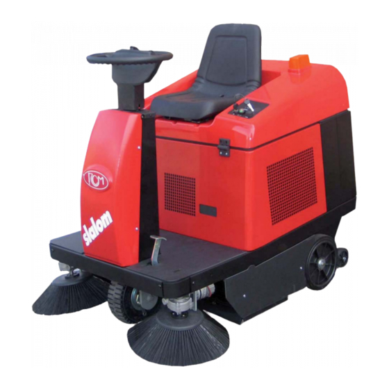
Page 19: Comandi
ITALIANO COMANDI (FIG.1) 1) Interruttore (a chiave) per avviamento a due posizioni. Comanda l’inserimento dell’impianto generale Pos.0 = impianto disinserito - chiave estraibile, Pos.1 = impianto inserito 2) Pulsante avvisatore acustico Comanda l’avvisatore acustico. 3) Spia stato di carica delle batterie. La spia indica con colori diversi lo stato di carica delle batterie. - Page 20 ITALIANO 11) Vite regolazione spazzola centrale Serve per registrare la spazzola quando è consumata, oppure quando la spazzola lascia segni di sporco mentre lavora. Per un buon funzionamento, la spazzola deve sf orare il terreno, lasciando una traccia “A” a terra di 3 cm di larghezza (f g. 2). - regolare la traccia allentando la vite e spostandola verso l’alto o basso del settore asolato.
-
Page 21: Norme Di Sicurezza Generali
ITALIANO NORME DI SICUREZZA GENERALI La macchina descritta nel presente manuale è stata costruita in conformità alla Direttiva Comunitaria sulle macchine 98/37/CE (Direttiva Macchine). È obbligo del responsabile della gestione della macchina attenersi alle direttive comunitarie e alle leggi nazionali vigenti, nei riguardi dell’ambiente di lavoro, ai f ni della sicurezza e della salute degli operatori. -
Page 22: Uso Della Motoscopa
ITALIANO USO DELLA MOTOSCOPA Precauzioni necessarie - La motoscopa deve essere usata solamente da persone competenti e responsabili. - Quando si lascia la motoscopa incustodita, occorre togliere la chiave e frenarla mediante pedale 5 f g1 e maniglia di bloccaggio 9 f g.1. - Non fermare la macchina in pendenza. -
Page 23: Norme Da Seguire Durante Il Funzionamento
ITALIANO NORME DA SEGUIRE DURANTE IL FUNZIONAMENTO Non raccogliere corde, f li di ferro, reggette, acqua, ecc. In presenza di oggetti voluminosi e particolarmente leggeri (carta, foglie, ecc.) sollevare il f ap anteriore della motoscopa mediante pedale 4 (Fig.1); questa manovra va ef fettuata solamente per il tempo necessario alla raccolta dei suddetti oggetti. -
Page 24: Spazzola Centrale
ITALIANO SPAZZOLA CENTRALE (FIG.3) La spazzola centrale è l’organo che carica i rif uti nel contenitore posteriore. Attenzione ! Non raccogliere fi li, corde, ecc., poiché, avvolgendosi alla spazzola, possono danneggiare le setole. Smontaggio/montaggio spazzola centrale La spazzola centrale è smontabile dal lato sinistro della motoscopa, le operazioni di smontaggio e rimontaggio devono essere effettuate nel seguente ordine: - aprire lo sportello 6 ispezionamento spazzola ;... -
Page 25: Spazzola Laterale
ITALIANO SPAZZOLA LATERALE (FIG.4) La funzione delle spazzole laterali è quella di pulire lo sporco negli angoli e lungo i bordi e convogliarlo sulla scia della spazzola centrale. Sostituzione spazzola laterale - Svitare le tre viti 1 e la spazzola si stacca dal suo supporto. - Dopo aver montato la nuova spazzola, eseguire nuovamente le operazioni di regolazione. -
Page 26: Ventola Aspirazione
ITALIANO VENTOLA DI ASPIRAZIONE (FIG.8) La ventola di aspirazione 1 è l’organo che serve ad aspirare la polvere creata dalle spazzole. La ventola è azionata dal pulsante 8 su posizione “B”, vedere “comandi - FIG.1”. Attenzione! In presenza di acqua sul terreno da spazzare, chiudere l’aspirazione mediante il pulsante 8 Fig.1 su pos.A Quando si eseguono trasferimenti con la motoscopa , agire nel seguente modo: - interrompere la rotazione delle spazzole (vedi “comandi”... -
Page 27: Impianto Elettrico
ITALIANO IMPIANTO ELETTRICO L’impianto elettrico ha una tensione di 24 V ed è formato da: un gruppo di due batterie da 12V - 140Ah (Fig12A), oppure da quattro batterie da 6V - 180Ah (Fig.12B) La motoscopa non deve essere mai utilizzata f no al completo esaurimento delle batterie. Quando la luce gialla sulla spia 3 (f g.1) è... -
Page 28: Caricabatterie A Bordo
ITALIANO OPTIONAL CARICA BATTERIA A BORDO (FIG.13) Quando la batteria è scarica (vedi spia 3 f g.1) ricaricarla mediante carica batteria 1. Procedere nel seguente modo: - LEGGERE ATTENTAMENTE IL MANUALE OPERATIVO 2 DEL CARICA BATTERIE IN DOTAZIONE. - estrarre la spina del carica batterie. - assicurarsi che la tensione della rete elettrica sia 220V. -
Page 29: Operazioni Periodiche Di Controllo E Manutenzione
ITALIANO OPERAZIONI PERIODICHE DI CONTROLLO E MANUTENZIONE 1) La motoscopa deve essere ispezionata da un tecnico specializzato che controlli le condizioni di sicurezza della macchina o la presenza di eventuali danni o difetti nei seguenti casi: • prima della messa in funzione •... -
Page 30: Ricerca Dei Guasti
ITALIANO RICERCA DEI GUASTI DIFETTO CAUSA RIMEDIO ON RACCOGLIE MATERIALI PESANTI E LASCIA TRACCIA DI ELOCITÀ DI AVANZAMENTO ECCESSIVA IMINUIRE VELOCITÀ DI AVANZAMENTO SPORCO DURANTE IL LAVORO RACCIA TROPPO LEGGERA EGOLARE TRACCIA PAZZOLE CONSUMATE EGOLARE TRACCIA O SOSTITUIRE SPAZZOLE PAZZOLA CON SETOLE PIEGATE O CON AVVOLTO IMUOVERE FILI DI FERRO CORDE... -
Page 31: Informazioni Di Sicurezza
ITALIANO INFORMAZIONI DI SICUREZZA 1) Pulizia: Nelle operazioni di pulizia e di lavaggio della macchina i detergenti aggressivi, acidi, ecc. devono essere usati con cautela. Attenersi alle istruzioni del produttore dei detergenti, e, nel caso, usare indumenti protettivi (tute, guanti, occhiali, ecc.). -
Page 32: Preliminary Information
ENGLISH PRELIMINARY INFORMATION This symbol attracts attention to important safety regulations which must be applied to avoid injury or dam- age to your property or that of others. Before starting work with your motor-sweeper , read all the instructions in this manual and the engine manual carefully, and follow them to the letter. -
Page 33: Generalities
ENGLISH GENERALITIES Data for sweeper identifi cation type plate... -
Page 34: Controls
ENGLISH CONTROLS (FIG.1) 1) Two position starting key switch. Controls the main electric system Pos.0 = electric system deactivated - the key can be removed, Pos.1 = electric system activated 2) Horn button Push the button to operate the horn. 3) Battery warning light. -
Page 35: Accelerator Pedal
ENGLISH 11) Main brush adjusting screw If the main brush is worn or leaves lines of dirt, adjust it with the properly screw. The main brush should just touch the f oor, leaving a “A” trace 3 cm wide when it rotates (f g.2 ). - loosen the screw and move it up or down through the slotted hole to adjust the trace. -
Page 36: General Safety Rules
ENGLISH GENERAL SAFETY RULES The machine described in this manual has been constructed in accordance with the Community Directive on machinery 98/37/CE (Machinery Directive) . The person in charge of the machine is responsible for compliance with the Community directive and the national laws in force with regard to the working environment, for the purposes of the health and safety of operatives. -
Page 37: Operating The Sweeper
ENGLISH OPERATING THE SWEEPER Precautions - The sweeper should only be used by competent and authorised personnel. - Always remove the key and apply the parking brake by the pedal 5 f g.1 and lock it by the handle 9, f g. 1 when leaving the sweeper unattended. -
Page 38: Regulations To Be Followed During Operation
ENGLISH REGULATIONS TO BE FOLLOWED DURING OPERATION Never sweep up ropes, wire, straps, water, etc. To pick up large but light objects (such as paper , leaves, etc.), raise the front f ap of the machine by pedal 4 (f g.19 slightly for just the time necessary to sweep the objects up. Shake the f lters from time to time by the switch 8 f g. -
Page 39: Main Brush
ENGLISH MAIN BRUSH (FIG.3) The main brush sweeps dust and refuse into the refuse container at the rear of the sweeper. Warning ! Never sweep up string, wire, etc., which can become entangled in the brush and damage the bristles. Removing/mounting the main brush The main brush can be removed from the left side of the sweeper. -
Page 40: Side Brush
ENGLISH SIDE BRUSH (FIG.4) The side brushes sweep dirt from the edges of f oors and from corners, and direct it to the centre of the sweeper where it can be picked up by the main brush. Replacing the side brush - Remove the three bolts 1, which f x the brush to the hub, and remove the old brush. -
Page 41: Vacuum Fan
ENGLISH VACUUM FAN (FIG.8) The vacuum fan 1 sucks up the dust raised by the brushes. Warning! Shut off the vacuum system by pressing the switch 8 fi g.1 to position “A” when working on wet fl oors. When driving the motor-sweeper from one place to another without, proceed as follows: - stop the turning of the brushes (see “controls”, f g.1 - point 6). -
Page 42: Electrical System
ENGLISH ELECTRICAL SYSTEM The electrical system operates at 24 V and is powered by two 12 V - 140 Ah batteries or four 6 V - 180 Ah bat- teries Never continue operating the sweeper until the batteries run completely f at. When indicator 3 (f g.1) shows yellow, the batteries are starting to run down. -
Page 43: Optionals
ENGLISH OPTIONALS BATTERY CHARGER ON BOARD (FIG.13) Use it when the battery is discharged (see warning light 3 f g.1) Proceed as belows: - READ CAREFULLY THE OPERATIONS MANUAL 2 OF THE BATTERY CHARGER 1. - take out the plug of the battery charger. - make sure that the electric power supply is 220V. -
Page 44: Safety Checks
ENGLISH SAFETY CHECKS 1) The sweeper must be inspected by a specialist technician who checks its safety or for any damage or de- fects in the following cases: • before it is put into operation • after modif cations or repairs •... -
Page 45: Troubleshooting
ENGLISH TROUBLESHOOTING PROBLEM CAUSE CORRECTIVE ACTION HE WEEPER FAILS TO PICK UP LARGE PARTICLES OF DIRT ORKING SPEED TOO FAST EDUCE WORKING SPEED OR LEAVES TRACES OF DIRT BEHIND RUSH PRESSURE TOO LIGHT DJUST BRUSH PRESSURE RUSHES WORN DJUST BRUSH PRESSURE OR REPLACE BRUSHES RISTLES BENT OR STRING OR WIRE ENTAN... -
Page 46: Safety Information
ENGLISH SAFETY INFORMATION 1) Cleaning: When cleaning and washing the machine, take care when using aggressive detergents, acids, etc. Follow the instructions provided by the detergent producer, and wear protective clothing if appropriate (e.g. overalls, gloves, goggles, etc. - see CE directives on this subject). 2) Explosive atmosphere: The machine is not constructed to work in environments where there is a risk that there might be explosive gases, dusts or vapours, and so its use in an explosive atmosphere is FORBIDDEN. -
Page 47: Información Preliminar
ESPAÑOL INFORMACIÓN PRELIMINAR Este símbolo indica las normas de seguridad importantes que, de no seguirse, pueden causar daños per- sonales y/o materiales, ya sean de su propiedad o ajenos. Antes de poner en funcionamiento su barredora, lea con atención todas las instrucciones del presente manual y del manual del motor térmico que está montado en esta máquina y respete las indicaciones facilitadas. - Page 48 ESPAÑOL GENERALIDADES Datos de identifi cación de la barredora Placa de resumen...
- Page 49 ESPAÑOL MANDOS (FIG.1) 1) Interruptor (llave) de arranque de dos posiciones. Pone en servicio el sistema eléctrico principal Pos.0 = sistema eléctrico apagado - llave extraible, Pos.1 = sistema eléctrico activado 2) Pulsador del claxon Manda el avisador acustico 3) Indicador de carga de las baterias. Este indicador indica con colores diferentes el estado de carga de las baterías.
- Page 50 ESPAÑOL 11) Tornillo de regulación del cepillo central Regular el cepillo cuando està desgastado o cuando deja la suciedad en el pavimento durante el trabajo. El cepillo central sólo debe rozar el suelo, dejando una marca “A” de 3 cm de ancho a lo largo de su trayecto (Fig. 2). - af ojar y desplazar el tornillo en el ojal para regular la marca.
-
Page 51: Normas Generales De Seguridad
ESPAÑOL NORMAS GENERALES DE SEGURIDAD La máquina descrita en este manual ha sido fabricada de acuerdo con la Directiva Comunitarioa para máquinas 98/37/CE (Directiva para máquinas) y con las posteriores enmiendas de ésta. El responsable del manejo de la máquina deberá respetar las directivas comunitarias y las leyes nacionales vigentes referentes al lugar de trabajo, a f n de mantener las condiciones de seguridad y de higiene para los trabajadores. -
Page 52: Uso De La Barredora
ESPAÑOL USO DE LA BARREDORA Precauciones necesarias - La barredora debe ser utilizda únicamente por personas competentes y responsables. - Cuando se deja la barredora sin vigilancia, hay que quitar la llave y accionar el freno por medio del pedal 5 (Fig. -
Page 53: Normas Que Deben Seguirse Durante El Funcionamiento
ESPAÑOL NORMAS QUE DEBEN SEGUIRSE DURANTE EL FUNCIONAMIENTO No recoger cuerdas, alambres, palos, agua, etc. Para recoger material voluminoso y muy ligeros (como papeles, hojas, etc.) subir la aleta delantera de la barre- dora pisando el pedal 4 (f g. 1) ; esta maniobra debe efectuarse sólo durante el tiempo que dure la recogida de dichos objetos. -
Page 54: Desmontaje/Montaje Del Cepillo Central
ESPAÑOL CEPILLO CENTRAL (FIG.3) El cepillo central es la pieza que carga la basura en el contenedor posterior. ¡Atención! No recoger nunca cuerdas, alambres, etc. puesto que podrían enrollarse en el cepillo y deteriorar las cerdas. Desmontaje/montaje del cepillo central El cepillo central se desmonta por el lado izquierdo de la barredora y las operaciones de desmontaje y montaje deben efectuarse siempre en el orden siguiente: - Abrir la compuerta 6 de inspección del cepillo central. -
Page 55: Cepillo Lateral
ESPAÑOL CEPILLO LATERAL (FIG.4) La función del cepillo lateral es la de limpiar la suciedad de las esquinas y a lo largo de los bordes y conducirla hacia el trayecto del cepillo central. Sustitución del cepillo lateral - Destornillar los tres tornillos 1 y separar el cepillo del soporte. - Después de haber montado el cepillo nuevo, volver a efectuar las operaciones de regulación. -
Page 56: Ventilador De Aspiración
ESPAÑOL VENTILADOR DE ASPIRACIÓN (FIG.8) El ventilador de aspiración 1 es el componente que aspira el polvo que levantan los cepillos El ventilador se acciona por el interruptor 8 en posición “B”, ver “mandos - FIG.1”. ¡Atención! Si hay agua en el suelo que se va a barre, deberá cerrarse la aspiración por medio del interruptor 8 f g.1 en posición A. -
Page 57: Instalación Eléctrica
ESPAÑOL INSTALACIÓN ELÉCTRICA La instalación eléctrica tiene una tensión de 24 V y está formada por: un conjunto de dos baterías de 12V - 140Ah ó quatro baterias de 6V - 180Ah (Fig.12B) La barredora nunca debe utilizarse hasta agotar completamente las baterías. Cuando se enciende la luz am- arilla del testigo 3 (f g.1), signif ca que las baterías empiezan a descargarse completamente. -
Page 58: Características Técnicas
ESPAÑOL OPCIONES CARGADOR DE BATERIÁ INCORPORADO (IG.13) Cuando la batería está descargada (ver testigo 3 f g.1) recargarla por medio del cargador 1. Proceder de la siguiente manera: - LEER CUIDADOSAMENTE EL MANUAL DE USO 2 DEL CARAGADOR ADQUIRIDO. - extraer la toma del cargador. - comprobar que la tensión eléctrica sea 220V. - Page 59 ESPAÑOL OPERACIONES PERIÓDICAS DE COMPROBACIÓN Y MANTENIMEINTO 1) La motoscopa deve essere ispezionata da un tecnico specializzato che controlli le condizioni di sicurezza della macchina o la presenza di eventuali danni o difetti nei seguenti casi: • prima della messa in funzione •...
-
Page 60: Búsqueda De Averías
ESPAÑOL BÚSQUEDA DE AVERÍAS PROBLEMA CAUSA SOLUCIÓN O RECOGE MATERIALES PESADOS O DEJA UNA MARCA ELOCIDAD DE MARCHA DEMASIADO ELEVADA ISMINUIR LA VELOCIDAD DE MARCHA DE SUCIEDAD DURANTE LA OPERACIÓN ARCA DEMASIADO LIGERA EGULAR LA MARCA EPILLO GASTADO EGULAR LA ALTURA O CAMBIAR LOS CEPILLOS EPILLO CON LAS CERDAS DOBLADAS O CON ALAM UITAR EL MATERIAL ENROLLADO BRES... -
Page 61: Medidas De Seguridad
ESPAÑOL MEDIDAS DE SEGURIDAD 1) Limpieza: En las tareas de limpieza y lavado de la máquina deben utilizarse con precaución los detergentes agre- sivos, ácidos, etc. Seguir ls instrucciones del fabricante de dichos productos, y si fuera necesario utilizar ropas de protección (monos, guantes, gafas, etc.). -
Page 62: Informations Preliminaires
FRANÇAIS INFORMATIONS PRELIMINAIRES Ce symbole attire l’attention sur les normes de sécurité importantes dont la violation peut causer des dom- mages à la sécurité personnelle et/ou à votre propriété ou à celle d’autrui. Avant d’utiliser votre balayeuse, lisez attentivement toutes les instructions de ce manuel et de celui du moteur thermique installé... -
Page 63: Generalites
FRANÇAIS GENERALITES Données pour l’identifi cation de la balayeuse Plaquette d’identifi cation... -
Page 64: Commandes
FRANÇAIS COMMANDES (FIG.1) 1) Interrupteur (a clé) d’allumage à deux positions Il sert à actionner l’installation électrique générale Pos.0 = installation activée - clé amovible Pos.1 = installation désactivée 2) Bouton d’actionnement du klaxon Le bouton commande le klaxon 3) Témoin d’indication de l’état de charge de la batterie Ce témoin indique avec plusieurs couleurs l’état de charge de la batterie. -
Page 65: Vis De Réglage Du Balai Central
FRANÇAIS 11) Vis de réglage du balai central il sert à régler la balai quand il est usé ou quand il laisse de la saleté durant le travail. Pour un bon fonctionnement, le balai doit frôler le terrain, en y laissant une trace “A” de 3 cm de large (f g.2). - dévisser la vis et la placer vers le haut ou bas de l‘oeillet pour régler la trace. -
Page 66: Normes De Surété Générales
FRANÇAIS NORMES DE SURÉTÉ GÉNÉRALES La machine décrite dans le présent manuel a été réalisée en conformité avec la Directive Communautaire sur les machines 98/37/CE (Directive Machines) et ses modif cations successives. Le responsable de la gestion de la machine doit impérativement se conformer aux directives communautaires ainsi qu’aux lois nationales en vigueur en ce qui concerne l’environnement de travail, a f n de sauvegarder la sécurité... -
Page 67: Emploi De La Balayeuse
FRANÇAIS EMPLOI DE LA BALAYEUSE Précautions nécessaires - La machine ne doit être utilisée que par des personnes formées et responsables. - Lorsqu’on laisse la balayeuse sans surveillance, il faut enlever la clé 3 (f g.4) et l’arrêter par le frein 7 (f g.4). - Lorsque la balayeuse est à... -
Page 68: Normes À Suivre Au Cours Du Fonctionnement
FRANÇAIS NORMES À SUIVRE AU COURS DU FONCTIONNEMENT - Ne pas ramasser de cordes, f ls de fer, feuillards, eau, etc. - En présence d’objets volumineux et notamment légers (papier , feuilles, etc.) soulever le f ap avant de la balayeuse en appuyant sur la pédale 4 ( f g. -
Page 69: Balai Central
FRANÇAIS BALAI CENTRAL (FIG.3) Le balai central est la partie qui ramasse les déchets et les verse dans le bac arrière. Attention! Ne jamais ramasser de fi ls, cordes etc...car ils peuvent endommager les poils s’ils s’enroulent au balai. Démontage et remontage du balai central Le balai central peut être démonté... -
Page 70: Balai Lateral
FRANÇAIS BALAI LATERAL (FIG.4) Les balais latéraux ont pour but de nettoyer la saleté dans les coins et le long des bords et l’amener sur le sil- lage du balai central. Remplacement du balai lateral - Dévisser les trois écroux 1 pour enlever le balai de son support. - Apres le montage du nouveau balai, exécuter les operations de réglage. -
Page 71: Ventilateur D'aspiration
FRANÇAIS VENTILATEUR D’ASPIRATION (FIG.8) Le ventilateur d’aspiration 1 est l’élément qui sert à aspirer la poussière créée par les balais. Le ventilateur est actionné à l’aide d’un interrupteur 8 sur pos. “B”, voir “commandes - FIG.1”. Attention! En présence d’eau sur le sol à balayer, fermer l’aspiration au moyen de l’interrupteur 8 Fig.1 sur pos.A Pendant les transferts avec la balayeuse, agir comme suit: - Fermer la rotation des balais (voir“commandes”... -
Page 72: Installation Électrique
FRANÇAIS INSTALLATION ÉLECTRIQUE L’installation électrique a une tension de 24 V et est formée par: un groupe de 2 batteries de 12 V – 140 Ah (f g.12A) ou 4 batteries de 6V - 180Ah (f g.12B) La balayeuse ne doit jamais être utilisée jusqu’à épuisement complet des batteries. Lorsque la lumière jaune du témoin 3 ( f g.1) est allumée, cela signi f e que les batteries sont en train de s’épuiser. -
Page 73: Options
FRANÇAIS OPTIONS CHARGEUR DE BATTERIE À BORD (FIG.13) Lorsque la batterie est déchargée (voir témoin 3 f g.1) la recharger à l’aide du chargeur 1. Procéder comme suit: - LIRE ATTENTIVEMENT LE MANUEL DU CHARGEUR EN DOTATION. - extraire la f che du chargeur. - s’assurer que la tension du réseau électrique soit de 220V. -
Page 74: Opérations Périodiques De Contrôle Et Entretien
FRANÇAIS OPÉRATIONS PÉRIODIQUES DE CONTRÔLE ET ENTRETIEN 1) La balayeuse doit être révisée par un technicien spécialisé, qui devra contrôler les conditions de sécurité de la machine ou la présence de dommages ou de défauts éventuels dans les cas suivants: •... -
Page 75: Recherche Des Pannes
FRANÇAIS RECHERCHE DES PANNES DEFAUT CAUSE REMEDE ’ A MACHINE NE RAMASSE PAS D ORDURES LOURDES ET ’ ’ ITESSE D AVANCE EXCESSIVE IMINUER LA VITESSE D AVANCE LAISSE DES TRACES DE SALETÉ LORS DU FONCTIONNEMENT RACE TROP LÉGÈRE ÉGLER LA TRACE ALAI USÉ... -
Page 76: Informations De Surété
FRANÇAIS INFORMATIONS DE SURÉTÉ 1) Nettoyage: Quant aux opérations de nettoyage et de lavage de la machine, utiliser avec précaution les détergents agressifs, les acides, etc. S’en tenir aux instructions du producteur des détergents et, au besoin, utiliser des vêtements de protection (tels que survêtements, gants, lunettes, etc. - Page 77 FIG.1 A B B C C...
- Page 78 FIG.2...
- Page 79 FIG.3 FIG.3...
- Page 80 FIG.4 FIG.5A ’ : 178658) FINO MATR UP TO SERIAL NR HASTA LA MATR JUSQU À AU N SÈRIE BIS SERIEN TOT SERIENUMMER FIG.5B : 178659) DA MATR FROM SERIAL NR DESDE LA MATR À AU PARTIR DU N SÈRIE VON SERIEN GELDIG VAN SERIENUMMER FIG.6...
- Page 81 FIG.7 FIG.8...
- Page 82 FIG.9 FIG.10 SENSO DI MARCIA DRIVE DIRECTION FIG.11...
- Page 83 FIG.12 FIG.12A FIG.12B FIG.13 FIG.14...
- Page 84 FIG.15 (1/2) ’ : 178658) FINO MATR UP TO SERIAL NR HASTA LA MATR JUSQU À AU N SÈRIE BIS SERIEN TOT SERIENUMMER...
- Page 85 FIG.15 (2/2) ’ : 178658) FINO MATR UP TO SERIAL NR HASTA LA MATR JUSQU À AU N SÈRIE BIS SERIEN TOT SERIENUMMER...
- Page 86 DESCRIZIONE SCHEMA ELETTRICO (fi g.15a) ELECTRIC SYSTEM DESCRIPTIONS (fi g.15a) 1) Batteria 1) Battery 2) Motore spazzola centrale 2) Motore spazzola centrale / Main brush motor 3) Motore aspirazione (elettroventola) 3) Vacuum electric fan 4) Scuotif ltro 4) Shaker 5) Motore spazzola laterale 5) Side brush motor 6) Motore spazzola laterale 6) Side brush motor...
- Page 87 DESCRIPCIÓN DE LA INSTALLACIÓN ELÉCTRICA (fi g.15a) DESCRIPTION DE L’INSTALLATION ÉLECTRIQUE (fi g.15a) 1) Baterìa 1) Batterie 2) Motor del cepillo central 2) Moteur du balai central 3) Motor aspiración (eléctroventilador) 3) Moteur d’aspiration (électro-ventilateur) 4) Sacudidor 4) Secoueur 5) Motor del cepillo lateral 5) Moteur du balai lateral 6) Motor del cepillo lateral 6) Moteur du balai lateral...
- Page 88 FIG.15 (1/2) : 178659) DA MATR FROM SERIAL NR DESDE LA MATR À AU PARTIR DU N SÈRIE VON SERIEN GELDIG VAN SERIENUMMER...
- Page 89 FIG.15 (2/2) : 178659) DA MATR FROM SERIAL NR DESDE LA MATR À AU PARTIR DU N SÈRIE VON SERIEN GELDIG VAN SERIENUMMER...
- Page 90 DESCRIZIONE SCHEMA ELETTRICO (fi g.15b) ELECTRIC SYSTEM DESCRIPTIONS (fi g.15b) J1 - J1 - J2 Centralina elettronica J2 Electronic control unit J3 Connettore per caricabatterie (optional) J3 Battery charger connector (optional) J4 Connettore per motori spazzole laterali J4 Side brush motors connector J5 - J5 - J6 -...
- Page 91 DESCRIPCIÓN DE LA INSTALLACIÓN ELÉCTRICA (fi g.15b) DESCRIPTION DE L’INSTALLATION ÉLECTRIQUE (fi g.15b) J1 - J1 - J2 Electronic control unit Unidad eléctronica J2 Unitée électronique J3 Conector del cargador de batería (optional) J3 Connecteur du chargeur de batterie (option) J4 Conector para motor del cepillo lateral J4 Connecteur des moteurs des brosses laterales J5 -...
-
Page 92: Descrizione Allarmi
DESCRIZIONE ALLARMI (Diagnostica LED S1 - Fig.15B - versione elettrica) Contattare il Servizio Assistenza. Nr. Lampeggi Descrizione allarme Rimedio Micro di marcia avanti inserito all’accensione. Portare a riposo il riferimento di velocità ed aprire il micro marcia avanti. Micro di marcia indietro inserito all’accensione. Portare a riposo il riferimento di velocità... -
Page 93: Descripción De Las Alarmas
DESCRIPCIÓN DE LAS ALARMAS (Diagnostico LED S1 - Fig.15B - vers.eléctrica) Contactar el servicio de asistencia autorizado. Nr. Centelleos Descripción de los centelleos Remedio Microinterruptor de marcha adelante activado en Poner en posición “0” la referencia de velocidad y abrir el microinterruptor de marcha adelante. fase de encendido.