Publicité
Les langues disponibles
Les langues disponibles
Liens rapides
DEALERS: Give these instructions to your customers.
INITIAL SET-UP
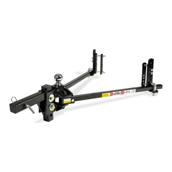
1. Line up
tow vehicle and trailer on level pavement,
in straight-ahead position, uncoupled.
2. Level the trailer and measure and record the
distance from the ground to the top of the ball
socket (dimension Fig. 1).
3. Select a hitch ball with a diameter that matches
the trailer coupler size. The three most common
sizes are 1-7/8", 2", and 2-5/16". Select ball with
1-1/4" or 1" threaded shank that is V-5 rated equal
to or greater than trailer gross vehicle weight
rating (GVWR).
WARNING: Raised balls usually have reduced load
ratings. Ball rating MUST equal or exceed trailer GVWR.
4. Attach hitch ball to the ballmount (G). REESE standard height hitch balls
with 1-1/4" shanks are supplied with lock washers and nuts (If you must use
a 1" shank ball, use bushing 58109 (B) to reduce hole size in ballmount (G)
to 1"). Always use a lock washer and place washer next to nut. Unless other-
wise specified by ball manufacturer torque ball nut to 450 ft/lbs for 1-1/4" nut,
250 ft/lbs for 1" nut.
5. Some installations may require a longer hitch bar (D). Extended bumper guards, pickup truck "caps", or rear mounted spare tires
can limit turn angles unless a longer bar is used. Individual hitch bars (D) are available in various sizes.
6. Insert the hitch bar (D) into the hitch box and install a pull pin. Place ballmount (G) onto hitch bar and move up or down for proper
height. Hitch bar may be used in either the up or down position (see Fig. 2).
NOTE: Ball height should be greater than coupler height (measured in step 1) to compensate for vehicle "squat"
(approximately 3/4" to 1").
For Installation Assistance or Technical Help, Call 1-800-632-3290
65509IN-03/09/16 REV. M
INSTALLATION INSTRUCTIONS
Heavy Duty Round Bar Adjustable
Weight Distributing Hitches
Fig. 1
PCN6540
© 2000, 2016 CEQUENT PERFORMANCE PRODUCTS, INC.
PACKAGES 66014K AND 61224
E
D
J
B
F
G
Fig. 2
Printed in Mexico
SMALL PARTS
L
K
PAGE 1 OF 4
Publicité

Manuels Connexes pour Cequent Performance Products 66014K


Sommaire des Matières pour Cequent Performance Products 66014K
- Page 1 NOTE: Ball height should be greater than coupler height (measured in step 1) to compensate for vehicle "squat” (approximately 3/4” to 1”). Fig. 2 Fig. 1 For Installation Assistance or Technical Help, Call 1-800-632-3290 65509IN-03/09/16 REV. M PCN6540 © 2000, 2016 CEQUENT PERFORMANCE PRODUCTS, INC. Printed in Mexico PAGE 1 OF 4...
- Page 2 5. Position the snap up brackets on trailer "A" frame so that the chain on the end of the spring bar is approximately vertical. Turn 1/2 X 3-1/2 bolt until it contacts frame. Then tighten 1/4 turn with wrench. DO NOT OVERTIGHTEN. 65509IN-03/09/16 REV. M PCN6540 © 2000, 2016 CEQUENT PERFORMANCE PRODUCTS, INC. Printed in Mexico PAGE 2 OF 4...
- Page 3 Place several drops of oil at spring bar / ballmount contact points. Excess oil, dirt, and grit should be wiped out when the trailer is uncoupled. Lubricate the hitch ball with automotive grease to prevent unnecessary wear. 65509IN-03/09/16 REV. M PCN6540 © 2000, 2016 CEQUENT PERFORMANCE PRODUCTS, INC. Printed in Mexico PAGE 3 OF 4...
- Page 4 LIMITED LIFETIME WARRANTY Limited Lifetime Warranty (“Warranty”). Cequent Performance Products, Inc. ("We", “Us” or “Our”) warrants to the original consumer purchaser only ("You" or “Your”) that the product will be free from material defects in both material and workmanship, ordinary wear and tear excepted.
- Page 5 For Installation or Operation Support contact CPP Technical Service: 1-800-632-3290 WARNING: Failure to follow all of these instructions may result in death or serious injury! © 2014 Cequent Performance Products, Inc. Sheet 1 of 33 26002IN 11/1/15 Rev. S...
- Page 6 WD40 or PB Blast to the threads of the cam arm. Work the adjustment nut back or forward to get the penetrating oil into the threads until the adjustment nut moves freely to the desired position. ADJUSTMENT NUT LOCK WASHER LOCK NUT YOKE Figure 5 © 2014 Cequent Performance Products, Inc. Sheet 2 of 33 26002IN 10/1/15 Rev. S...
- Page 7 The Measurements in figures 6, 6A, 7 & 7A are guidelines, adjustment of the cam arm length via the adjustment nut (Figure 5) may be required after hookup in later instructions of this manual Cequent Performance Products, Inc. is not responsible for damage incurred due to disregarding any part of this manual.
- Page 8 The Measurements in figures 6, 6A, 7 & 7A are guidelines, adjustment of the cam arm length via the adjustment nut (Figure 5) may be required after hookup in later instructions of this manual Cequent Performance Products, Inc. is not responsible for damage incurred due to disregarding any part of this manual.
- Page 9 ½ turn after contact with the frame. ½” hex head bolts with Tighten the ½” bolts on the outside of the lock washers frame. Torque to 75 ft. lbs. © 2014 Cequent Performance Products, Inc. Sheet 5 of 33 26002IN 10/1/15 Rev. S...
- Page 10 Tighten the Jam Nut preventing the set screw from backing out while in use. Repeat for other side of trailer frame. Remove C-Clamps from frame. HEX HEAD BOLT LOCK Figure 9 WASHER © 2014 Cequent Performance Products, Inc. Sheet 6 of 33 26002IN 10/1/15 Rev. S...
- Page 11 Check that the emergency brake is set Block in front of and behind all trailer tires Check that the trailer jack foot is resting on firm ground © 2014 Cequent Performance Products, Inc. Sheet 7 of 33 26002IN 10/1/15 Rev. S...
- Page 12 8. Run the adjustment nut shown in figure 5 down to meet the yoke. Tighten the locking nut shown in figure 5 until the locking washer is fully compressed. This process needs to be done for both cam assemblies, i.e. both sides of the trailer frame. © 2014 Cequent Performance Products, Inc. Sheet 8 of 33 26002IN 10/1/15 Rev.
- Page 13 Tongue weights in excess of 1,200 lbs. may require the use of such a lubricant to prevent excessive wear. 3. Keep all painted parts painted to prevent rust and maintain a good appearance. (Do Not paint over labels) © 2014 Cequent Performance Products, Inc. Sheet 9 of 33 26002IN 10/1/15 Rev.
- Page 14 1/2" x 1.00" SELF TAPPING SCREW INSTRUCTION SHEET For Installation or Operation Support contact CPP Technical Service: 1-888-521-0510. Cequent Performance Products, Inc. 47912 Halyard Dr. Suite 100 Plymouth, MI 48170 © 2014 Cequent Performance Products, Inc. Sheet 10 of 33 26002IN 10/1/15 Rev. S...
- Page 15 LIMITED LIFETIMEWARRANTY 1. Limited Warranty. Cequent Performance Products, Inc. (“We” or “Us”) warrants to the original consumer purchaser only (“You”) that the product will be free from material defects in both material and workmanship for lifetime of the product, ordinary wear and tear excepted;...
- Page 16 Pour de l'assistance concernant l'installation ou le fonctionnement, contacter le service technique CPP : 1-800-632-3290. AVERTISSEMENT : L'omission d'observer toutes les instructions peut causer des blessures sévères, voire la mort ! © Feuille 12 de 33 26002IN 10/1/15 Rev. S 2014 Cequent Performance Products, Inc.
- Page 17 Écrou de réglage Rondelle frein Écrou de blocage Fourche Figure 5 © Feuille 13 de 33 26002IN 10/1/15 Rev. S 2014 Cequent Performance Products, Inc.
- Page 18 Les mesures des figures 6, 6A, 7 et 7A sont à titre indicatif, un ajustement de la longueur du bras de came par l'écrou d'ajustement (Figure 5) peut s'avérer nécessaire après l'accrochage, dans les instructions à venir de ce manuel. Cequent Performance Products, Inc.
- Page 19 Les mesures des figures 6, 6A, 7 et 7A sont à titre indicatif, un ajustement de la longueur du bras de came par l'écrou d'ajustement (Figure 5) peut s'avérer nécessaire après l'accrochage, dans les instructions à venir de ce manuel. Cequent Performance Products, Inc.
- Page 20 Placer des cales à l'avant et l'arrière des pneus de la caravane. S'assurer que la béquille de la caravane repose sur un sol ferme. © Feuille 16 de 33 26002IN 10/1/15 Rev. S 2014 Cequent Performance Products, Inc.
- Page 21 NE PAS percer la paroi opposée du cadre tubulaire. 1. Avec les brides en C toujours en place, marquer au pointeau dans le cadre le centre de deux (2) trous pour chaque support. © Feuille 17 de 33 26002IN 10/1/15 Rev. S 2014 Cequent Performance Products, Inc.
- Page 22 Répéter de l’autre côté du cadre de remorque. 6. Retirer les brides en C du cadre. Boulon à tête hex. Plaque de cadre Figure 13 Rondelle frein © Feuille 18 de 33 26002IN 10/1/15 Rev. S 2014 Cequent Performance Products, Inc.
- Page 23 ½ tour après le contact avec le cadre. freins 8. Serrer les boulons ½ po sur l'extérieur du cadre. 9. Serrer au couple de 75 lb-pi. © Feuille 19 de 33 26002IN 10/1/15 Rev. S 2014 Cequent Performance Products, Inc.
- Page 24 Les charges au timon excédant 1200 lb peuvent nécessiter l'application de lubrifiant afin de prévenir l'usure excessive. 3. Maintenir la peinture en bon état afin de prévenir la rouille et conserver une apparence agréable. (Ne PAS peindre les étiquettes) © Feuille 20 de 33 26002IN 10/1/15 Rev. S 2014 Cequent Performance Products, Inc.
- Page 25 Pour de l'assistance concernant l'installation ou le fonctionnement, contacter le service technique CPP : 1-888-521-0510. Cequent Performance Products, Inc. 47912 Halyard Dr. Suite 100 Plymouth, MI 48170 © 2014 Cequent Performance Products, Inc. Feuille 21 de 33 26002IN 10/1/15 Rev. S...
- Page 26 Les cours de l’État situées dans le comté d’Oakland, Michigan, constituent les autorités judiciaires exclusives relativement à cette garantie. Cequent Performance Products, Inc. 47912 Halyard Dr., Suite 100 Plymouth, MI 48170 © Feuille 22 de 33 26002IN 10/1/15 Rev. S 2014 Cequent Performance Products, Inc.
- Page 27 Para instalación u operación contacte al Servicio Técnico de CPP: 1-800-632-3290. ADVERTENCIA: ¡No seguir estas instrucciones puede resultar en la muerte o en lesiones serias! © 2014 Cequent Performance Products, Inc. Hoja 23 de 33 26002IN 10/1/15 Rev. S...
- Page 28 Manipule la tuerca de ajuste hacia atrás o hacia adelante para que el aceite penetrante entre en las roscas hasta que la tuerca de ajuste se mueva libremente a la posición deseada. Tuerca de ajuste Arandela de bloqueo Tuerca de bloqueo Horquillla Figura 5 © 2014 Cequent Performance Products, Inc. Hoja 24 de 33 26002IN 10/1/15 Rev. S...
- Page 29 (Figura 5) podría ser necesario después de la instalación en instrucciones posteriores de este manual. Cequent Performance Products, Inc. no es responsable por daños incurridos por ignorar alguna parte de este manual. Hoja 25 de 33 26002IN 10/1/15 Rev. S © 2014 Cequent Performance Products, Inc.
- Page 30 (Figura 5) podría ser necesario después de la instalación en instrucciones posteriores de este manual. Cequent Performance Products, Inc. no es responsable por daños incurridos por ignorar alguna parte de este manual. Hoja 26 de 33 5/28/15 10/1/15 Rev. S © 2014 Cequent Performance Products, Inc.
- Page 31 Revise que el freno de emergencia esté activado Coloque bloques al frente y detrás de todas las llantas del remolque Revise que la base del gato del remolque esté apoyada en terreno firme © 2014 Cequent Performance Products, Inc. Hoja 27 de 33 26002IN 10/1/15...
- Page 32 NO perfore a través de la pared opuesta del tubo del bastidor. 1. Con las abrazaderas en C en su lugar, perfore (2) orificios en el bastidor para cada soporte. © 2014 Cequent Performance Products, Inc. Hoja 28 de 33 26002IN 10/1/15 Rev.
- Page 33 Repita para el otro lado del bastidor del remolque. Retire las abrazaderas en C del bastidor. PERNO CABEZA HEXAGONAL PLACA DEL BASTIDOR Figura 13 © 2014 Cequent Performance Products, Inc. Hoja 29 de 33 26002IN 10/1/15 Rev. S...
- Page 34 8. Apriete los pernos de ½” en el exterior del arandelas de bastidor. bloqueo 9. Apriete a 75 pies-lbs. © Feuille 32 de 33 26002IN 10/1/15 Rev. S 2014 Cequent Performance Products, Inc. - Impreso en México...
- Page 35 Las horquillas de peso superior a 1,200 lbs. podrían requerir el uso de lubricante para evitar el desgaste excesivo. 3. Mantenga todas las partes pintadas para evitar el óxido y mantener un buen aspecto. (No pinte sobre las etiquetas) © 2014 Cequent Performance Products, Inc. Hoja 31 de 33 26002IN 10/1/15 Rev.
- Page 36 Para apoyo con la instalación u operación, póngase en contacto con el Servicio Técnico de CPP: 1-888-521-0510. Cequent Performance Products, Inc. 47912 Halyard Dr. Suite 100 Plymouth, MI 48170 © 2014 Cequent Performance Products, Inc. Hoja 32 de 33 26002IN 10/1/15 Rev. S...
- Page 37 GARANTÍA LIMITADA DE POR VIDA 1. Garantía limitada. Cequent Performance Products, Inc. (“Nosotros" o “Nos”) garantiza al comprador original únicamente (“Usted”) que el producto está libre de cualquier defecto material tanto en materiales como de mano de obra por la duración del producto, con la excepción del desgaste habitual, siempre y cuando la instalación y el uso del producto se haga según las instrucciones...