
Manuels Connexes pour Dräger PointGard 3000 Serie


Sommaire des Matières pour Dräger PointGard 3000 Serie
- Page 1 Dräger PointGard 3000 Series Instructions for use enUS · de · fr · es · it · zh WARNING To properly use this product, read and comply with these instructions for use.
- Page 2 enUS Instructions for use ..............5 Gebrauchsanweisung ............50 Notice d'utilisation ..............98 Instrucciones de uso............147 Istruzioni per l'uso ...............195 使用说明 ................243 Dräger PointGard 3000 Series...
- Page 3 Dräger PointGard 3xx0 EC / CAT / IR NC COM NO NC COM NO NC COM NO (AC) (DC) M / - P / + M / - P / +...
- Page 4 Dräger PointGard 3100 EC Dräger PointGard 3100 EC Remote Dräger PointGard 3200 CAT Remote Dräger PointGard 3200 CAT Dräger PointGard 37x0 IR Remote SCR/PE SCR/PE 3 wires 5 wires SCR/PE 5 wires...
- Page 5 Contents Contents Dräger PointGard 3000 Series Safety-related information ............4.5.3 4-20mA Interface ............... 4.5.4 External error input ..............Safety statements............... Connecting the instrument to a controller from Dräger ....Operating area and conditions ........... Installing software dongles ............1.2.1 PointGard 3xx0 Remote ............. Mechanical installation ...............
- Page 6 Contents Gas flow for calibrations ............11.11 Display settings ................Zero calibration ................11.11.1 Changing the backlight color of the display........ 8.4.1 Performing zero calibration ............11.11.2 Changing the display contrast ............ Span calibration ................. 11.11.3 Changing the display mode............8.5.1 Performing span calibration ............
- Page 7 Contents Order list................... 14.7.1 Sensor test ................. 14.7.2 Gas settings ................Accessories and spare parts..........14.8 Sensor settings PointGard 3200 CAT ........14.8.1 Sensor type ................19.1 PointGard 3xx0 Series ............... 14.8.2 Gas settings ................19.1.1 PointGard 3xx0 Accessories............14.9 Sensor settings PointGard 37x0 IR ..........
- Page 8 Safety-related information Safety-related information Operating area and conditions – Observe the specifications and restrictions in the Instructions for Use and/ These instructions for use are available in further languages and can be or data sheets for the sensors. downloaded in electronic form on the according product website –...
- Page 9 Conventions in this document Electrical installation 1.5.1 Calibration – For proper operation, never adjust the span before completing zero – Strict compliance must be given to the electrical codes that govern the adjustment. Performing these operations out of order will cause the routing and connection of electrical power and signal cables to gas calibration to be faulty.
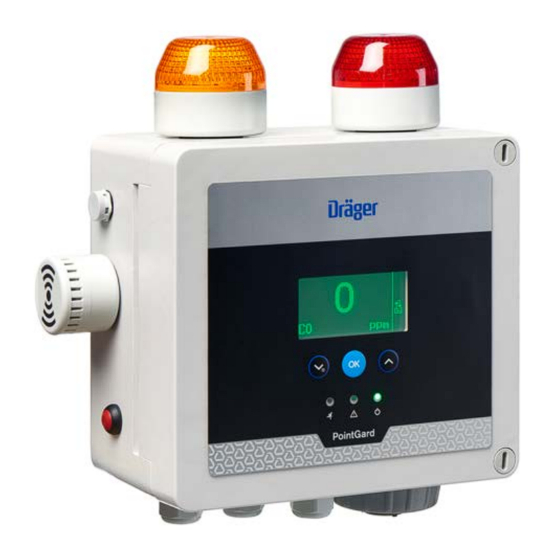
- Page 10 Description Description Alert icon Signal word Warning classification Drawing legend WARNING Indicates a potentially hazardous situa- tion. If not avoided, it could result in For figures, refer to the fold-out page.. death or serious injury. CAUTION Indicates a potentially hazardous situa- PointGard 3xx0 Series tion.
- Page 11 Description NOTICE Horn acknowledgment button For safety relevant indication use the visual indication on the front cover or the Rotary switch internal relay contacts only. The strobes and the horn shall not be used for safety relevant applications. PointGard 3100 EC Bayonet ring Alarm patterns of integrated alarm devices, such as flashing modes of the strobes and horn tones, can be configured with a DIP switch.
- Page 12 Description 3.2.2 PointGard 3200 CAT The following PIR 7000/7200 sensors can be connected remotely to a PointGard 3700/3720 IR. Only 5-core wiring is possible. The instrument monitors concentrations of combustible gases and vapors in – PIR 7000 continuously monitors combustible gases and vapors containing ambient air.
- Page 13 Mounting and installation Mounting and installation Mark Function Opening and closing the instrument Neutral WARNING Wiring table DC version Risk of electric shock Opening the instrument during operation can result in an electric shock. Mark Function ► Disconnect power from the instrument and wait at least 1 minute before M / - continuing.
- Page 14 Mounting and installation 1. Prepare an even surface following the assembly instruction (90 33 793) or WARNING the dimensions indicated on the back of the housing Risk of electric shock – Keep enough space clear for maintenance purposes and sensor Voltage differences can cause insulation faults.
- Page 15 Mounting and installation Wiring table 4-20 mA interface connection Mark Relay Mark Function Fault Normally Closed FAULT External error input A Fault Common FAULT External error input B Fault Normally Open 4 to 20 mA signal + Connecting the 9-pin connector 4 to 20 mA signal - 1.
- Page 16 Installation of sensors No function for variants without a green light. Remote versions with explosion protection "explosion proof (Ex d)" Transmitter Sensing head IFU part numbers Connecting the instrument to a controller PointGard 3200 CAT Junction Box stainless steel or alumi- from Dräger PointGard 3200 CAT Remote DSIR num (4544286)
- Page 17 Operation b. Check triggering of integrated alarm devices. This is the case: c. The optionally connected external relays – When the gas concentration exceeds the measuring range. – When a fault occurs. Operation – When alarms are deactivated. The measuring function (display output and analog/digital interface) remains The instrument is not SIL-certified even though SIL functions appear on the active.
- Page 18 Operation Warm-up phase 2 Display example Description symbol is displayed on the right side of the display. Fault indication The measured value is indicated on the left side of the display. symbol is displayed on the right side of Analog interface: Measured value the display.
- Page 19 Operation WARNING Symbol Explanation Ambiguous readings at over range measuring values Latching over range alarms are not supported with LC sensors. Maintenance signal is transmitted. ► After over range measuring values, verify that the gas concentration is below 100 %LEL (e.g. using a portable instrument). Measuring range of analog interface exceeded.
- Page 20 Operation Menu Button Function 7.6.1 Navigating in a menu Downwards / Menu key Button Function Different functions depending on the type of menu Scrolls upwards. Sets values. Info mode and function key Scrolls downwards. Sets values. 7.5.1 Activating info mode Confirms entry.
- Page 21 Calibration 7.6.4 Displaying Information Graph Displays the history of the past 15 minutes on a time/concentration graph. Select the appropriate menu item in the Information menu: Function only available with diagnostic dongle. Instrument Calibration Warnings Displays warning messages in plain text and the corre- sponding number.
- Page 22 Calibration Zero gas – Tubing (3) Zero gas is a test gas to calibrate the zero point. If ambient air is free from – Dräger calibration gas cylinder (4) interfering impurities and measured gas, it can be used as zero gas. For O Prepare calibration sensors, nitrogen (N ) is used.
- Page 23 Calibration Zero calibration Ambient air can be used to zero the sensor instead of Nitrogen or Synthetic Air only if the area is known to be free of the target gas or any gas to which the sensor may be cross-sensitive (as listed on the sensor data sheet). In this case, no cylinder or calibration adapter is needed for the zero calibration.
- Page 24 Calibration Perform zero calibration instrument response transmitted to the central device. In case of substances with particularly low calibration factors and/or manual configuration of a high 1. Select Calibration > Zero calibration and confirm. span calibration factor at the sensor, this may already happen at concentrations ...
- Page 25 Troubleshooting Changing the fuse Set the concentration of the calibration gas. 3. If settings are correct: 1. Open the instrument. a. Select Next and confirm. 2. Pull off the black fuse cover (14, 17 respectively) A message like Gas flow ON H S is displayed.
- Page 26 Troubleshooting Warnings Fault num- Cause Remedy Warning Cause Remedy Sensor lock function is Use a sensor with the same part number activated. A sensor with number or disable the sensor lock Supply voltage is out of Check supply voltage. a different part number function.
- Page 27 Maintenance ● To check LEDs and triggering of alarm devices, (see "Testing Warning Cause Remedy alarms/relays", page 31) number 10.1 Performing a bump test Negative reading. Value Recalibrate zero point. below range minimum. A bump test checks alarm activation without setting off the alarms. Low EC sensor vitality Replace sensor 1.
- Page 28 Maintenance – Performing the inspection (recommended every 6 months) c. Remove and discard the cover plate or old sensor respectively. – Cleaning the instrument using a soft cloth and water. Detergent must not be d. Remove the sensor from packaging and ensure that the sensor is a used.
- Page 29 Instrument settings 11.3 Setting language 2. Proceed as described in the manual of the sensing head. 3. Check calibration. If necessary, calibrate the instrument (see "Calibration", 1. Select Settings > Instrument > Language and confirm. page 21). 2. Select a language from the list and confirm 10.3.3 PointGard 3700/3720 IR Remote 11.4 Configuring function key...
- Page 30 Instrument settings 11.6 Combinations of latching and alarm Normally ener- The relay contact is energized during normal operation acknowledgment gized and changes if an alarm is triggered. At a loss of power this triggers an alarm (fail-safe). The following examples give an overview of relay acknowledgment Energ.
- Page 31 Instrument settings d. Set acknowledgement mode. Disable Alarm signaling is off. LEDs, relays and interfaces do not Acknowledgeable Alarm relay and LED can be reset before alarm condi- indicate an alarm condition. tion clears. The 4-20mA interface transmits the Alarm relay and LED can not be reset until the alarm Non-acknowl- maintenance signal.
- Page 32 Configuration of integrated alarm devices 2. Select Enable or Disable and confirm. Standard Shows the standard display. ✓ If the function is activated, the fault relay is de-energized and the 4 to 20 mA Non-display Shows the start screen and the appli- interface is set to the fault current.
- Page 33 Interface settings DIP switch default settings for amber/red strobe combination 3: 10 mins As soon as the alarm stops, the horn acknowledgment is reset and the horn will Pins be active again with next alarm. Interface settings 13.1 4-20mA interface DIP switch default settings for green/red strobe combination The current output of the instrument during normal operation is between 4 and 20 mA and is proportional to the detected gas concentration.
- Page 34 Interface settings 13.1.3 Information regarding the warning signal 13.1.7 Setting maintenance signal 1. Select Settings > Communication > Analog interface > Maint. signal To transmit a warning signal via the analog interface, the warning signal must and confirm. be switched on. The warning signal alternates between the warning current and the 2.
- Page 35 Interface settings 13.1.10 Setting analog span Set concentr. out / This function sets the preset mea- This function adjusts the analog output at 20 mA without affecting the 4 mA set set current out surement value or current test value. point.
- Page 36 Sensor settings PointGard 3xx0 14.2 Capture range If the build-up of deposits on the optical surfaces increases beyond the point where a measurement is possible, the instrument will go into fault. The capture range blanks out measurement fluctuations. Measurement ● To set beam block signals on/off: fluctuations are minor variations in measured values (such as signal noise, 1.
- Page 37 Sensor settings PointGard 3xx0 14.3 Resetting sensor 2. Select Deactivation func. The selected dongle is deactivated. This function resets the sensor to factory default settings. 14.7 Sensor settings PointGard 3100 EC 1. Select Settings > Sensor > Init. channel and confirm. 14.7.1 Sensor test 2.
- Page 38 Sensor settings PointGard 3xx0 14.9 Sensor settings PointGard 37x0 IR 6. After review, select Back to menu or Confirm. 14.9.1 Gas settings Back to menu Select Back to menu for leaving the function without changes and confirm This function sets the gas type, measuring range and units of measurement. with [OK].
- Page 39 Factory default settings Factory default settings Interface Default setting Range 15.1 Settings which can be changed via the menu Fault current 1.2 mA 0 to 3.5 mA 15.1.1 PointGard 3xx0 Warning On / Off Warning current 3.0 mA 0 to 3.5 mA Menu Default setting Range...
- Page 40 Factory default settings ® 15.2.3 PointGard 3200 CAT DrägerSensor Menu Default setting Range Menu Default setting Range Hysteresis for A2 alarm 0 to full scale deflection - at direction falling A1 Alarm 2.0 % LEL 0.1 to 10 % LEL Calibration interval Depending on the sen- 0 to 720...
- Page 41 Factory default settings Menu Default setting Range Menu Default setting Range Calibration interval 0 to 360 Beam block limit 7.5 %LEL 0 to max. 15 %LEL [days] Calibration inter- 0 to 720 Display capture offset 0 % LEL -3 to 4 % LEL [days] Display capture low -3 % LEL...
- Page 42 Factory default settings 15.2.6 PointGard 3720 IR Menu Default setting Range Menu Default setting Range A1 Alarm 20 %LEL 0.01 to 100 Vol% at unit %LEL = 0.3 to 100 %LEL Calibration gas A2 Alarm 40 %LEL Calibration gas Vol% LEL type NIOSH IEC / PTB / NIOSH / configurable...
- Page 43 Disposal Disposal Sensor Measuring range Type 334 (IDS 01x1) This product must not be disposed of as household waste. This is indi- 0 to 10,000 ppm cated by the adjacent icon. 0 to 100 %LEL, You can return this product to Dräger free of charge. For information 1)2) 0 to (1,25 x LELmax) Vol%, please contact the national marketing organisations and Dräger.
- Page 44 Technical data Impedance range Supply voltage range Nominal power PointGard 3100/3200 6 W at 24 V (DC), 25 °C 0 to 230 Ω at 10 V DC Nominal power PointGard 3700/3720 12 W at 24 V (DC), 25 °C Rising linearly with the supply volt- 10 to 18 V DC Cable specification 2 x 1.5 mm²...
- Page 45 Technical data Relative Humidity (operation) 0 … 95 % (non-condensing) Cable size 1 - 1.5 mm² (14-18 AWG) Relative Humidity (open door) 20 … 90 % (non-condensing) Max. 30 m /100 feet (DD/DQ sensor) Longitude Maximum operating altitude 2000 m / 6561 ft For further information regarding cable length and other possible cable specifications, see the ®...
- Page 46 Order list 17.9.2 Sensor range electrochemical (EC) sensors Range Default value Sensor Part number Range Default value Min. Defaul Max. Sensor Part number Min. Defaul Max. 6809685 1000 3000 6809605 1000 COCI2 6809930 CO LH 6812570 Hydrazin 6810180 CO LS 6809620 1000 5000...
- Page 47 Accessories and spare parts Description Order number Part Part number PointGard 3200 CAT AC remote 3728171 Mounting brackets 8326497 PointGard 3200 CAT AC remote green 3728170 19.1.2 Spare parts PointGard 3200 CAT DC 3728169 Part Part number PointGard 3200 CAT DC remote 3728168 Cable gland (M20 x 1.5) 8314595...
- Page 48 Accessories and spare parts For connections to a wall outlet, only Dräger power supply cables must be used. Part Part number For fixed installations the power supply cables must comply with the specifications in 17.3 Power supply. ® 6812711 Polytron SE Ex PR M1 DQ small standard housing (includes sensor) 19.1.4 Mounting screws...
- Page 49 Accessories and spare parts 19.4 PointGard 37x0 IR 19.4.1 Sensors Check firmware compatibility of sensor and transmitter. Changing the sensor may require a firmware update. For support, contact Dräger. Description Part number Dräger PIR 7000 Type 334 (NPT) 6811822 Dräger PIR 7000 Type 340 (NPT) 6811832 Dräger PIR 7000 334 (M25) 6811825...
- Page 50 Inhaltsverzeichnis Inhaltsverzeichnis Dräger PointGard 3000 Series Sicherheitsbezogene Informationen ........4.5.2 Relaisverbindungen..............4.5.3 4–20-mA-Schnittstelle ..............Sicherheitshinweise ..............4.5.4 Externer Fehlereingang.............. Einsatzbereich und Betriebsbedingungen ......... Das Gerät an ein Dräger-Auswertegerät anschließen ....1.2.1 PointGard 3xx0 Remote ............Software-Dongles installieren............. Mechanische Installation ............Elektrische Installation ...............
- Page 51 Inhaltsverzeichnis 8.2.1 Einrichten der Justierung............11.9 Alarme/Relais testen..............Gasdurchfluss für Justierungen..........11.10 Dongles deaktivieren ..............Nullpunktjustierung..............11.11 Displayeinstellungen ..............8.4.1 Nullpunktjustierung durchführen..........11.11.1 Farbe der Hintergrundbeleuchtung des Displays ändern ..Empfindlichkeitsjustierung............11.11.2 Kontrast des Displays ändern ............ 8.5.1 Empfindlichkeitsjustierung durchführen........11.11.3 Anzeigemodus ändern ...............
- Page 52 Inhaltsverzeichnis 14.6.1 Dongles deaktivieren ..............17.9.2 Sensorbereich elektrochemische (EC) Sensoren ...... 14.7 Sensoreinstellungen PointGard 3100 EC ........Bestellliste ................14.7.1 Sensortest.................. 14.7.2 Gaseinstellungen ............... Zubehör und Ersatzteile ............14.8 Sensoreinstellungen PointGard 3200 CAT ........ 14.8.1 Sensortyp................... 19.1 Serie PointGard 3xx0 ..............14.8.2 Gaseinstellungen ...............
- Page 53 Sicherheitsbezogene Informationen Sicherheitsbezogene Informationen – Wenn eine Komponente fehlerhaft ist oder eine Funktionsstörung vorliegt, Dräger benachrichtigen. Diese Gebrauchsanweisung kann in weiteren Sprachen auf der – An Geräten und Komponenten dürfen keine Änderungen vorgenommen entsprechenden Produktseite (www.draeger.com/ifu) in elektronischer Form werden. herunter geladen oder kostenlos als gedrucktes Exemplar über Dräger oder –...
- Page 54 Sicherheitsbezogene Informationen Mechanische Installation Ausführung mit Relais – Max. Stromstärke von 5 A für Relais erlaubt (SPDT-Kontakt 5 A bei – Die Verantwortung für den richtigen Anbringungsort des Geräts liegt beim 230 V AC, 5 A bei 30 V DC) Endbenutzer.
- Page 55 Konventionen in diesem Dokument – Methan und Wasserstoff sollten nur mit Zielgas und nicht mit Ersatzgas Warnzeichen Signalwort Klassifizierung des Warnhinweises justiert werden. HINWEIS Weist auf eine potenziell gefährliche Während des Betriebs Situation hin. Eine Missachtung kann zu Produkt- und Umweltschäden führen. Stromschlaggefahr Typografische Konventionen Der Versuch, das Gerät während des Betriebs zu öffnen, kann zu einem...
- Page 56 Beschreibung Signalhorn Bajonettring Schrauben zum Fixieren/Lösen der Abdeckung Einstellschraube (2-mm-Innensechskantschraube) Anschluss für die 4–20-mA-Schnittstelle Anschluss für EC-Sensor Kabelverschraubung für Netzanschlusskabel Verschlussstopfen des abgesetzten EC-Sensors Anschluss für Relais-Kabel Gehäuse des abgesetzten EC-Sensors Leiterplatten-Einheit PointGard 3200 CAT, 3200 CAT Remote, 37x0 IR Remote Steckplatz für Sensor-Dongle Steckverbinder für abgesetzten Sensor DIP-Schalter...
- Page 57 Beschreibung HINWEIS Diagnosedongle 83 17 860 Aktiviert den Sensor-Selbsttest, die Anzeige der Sensorvitalität und die Für sicherheitsrelevante Anzeigen nur die visuelle Anzeige an der Frontblende Sensordiagnosefunktionen (nur für oder die Kontakte der internen Relais verwenden. Die Stroboskopleuchten und bestimmte Sensoren und Funktionen) das Signalhorn dürfen nicht für sicherheitsrelevante Anwendungen verwendet werden.
- Page 58 Montage und Installation 3.2.4 PointGard 3700/3720 IR Remote HINWEIS PointGard 3700/3720 IR Remote kann an PIR 7000/7200 mit verschiedenen Für sicherheitsrelevante Anzeigen nur die visuelle Anzeige an der Frontblende Explosionsschutzarten angeschlossen werden. oder die Kontakte der internen Relais verwenden. Die Stroboskopleuchten und das Signalhorn dürfen nicht für sicherheitsrelevante Anwendungen verwendet ®...
- Page 59 Montage und Installation Steckverbinder für Spannungsversorgung Wenn ein nicht geschirmtes Kabel verwendet wird oder der Schutzleiter nicht angeschossen ist, Pin 1 und 2 überbrücken. und Verdrahtungstabellen 4. Schrauben des Steckverbinders mit dem richtigen Drehmoment (4.4 ... 5.3 Für den Anschluss des Netzkabels wird ein 3-poliger Steckverbinder Lbs.
- Page 60 Montage und Installation – Für Relais-Verbindungen: Kabelverschraubung 5 Verdrahtungstabelle Relaisverbindung – Für 4–20-mA-Schnittstellen-Anschlüsse: Kabelverschraubung 3 Bei Verwendung der Werkseinstellungen und während des Normalbetriebs sind die Relais erregt. Dadurch ist “fehlersicherer” Betrieb gewährleistet. 3. Die Kontermutter mit dem richtigen Drehmoment (13 +/- 4.4 Lbs. In. / 1.5 +/- 0.5 Nm) festziehen.
- Page 61 Montage und Installation 4. Gerät schließen. 5. Den Steckverbinder in die Buchse stecken und die Schrauben mit dem richtigen Drehmoment (1.9 ... 2.2 Lbs. In. / 0.22 ... 0.25 Nm) festziehen. 4.5.3 4–20-mA-Schnittstelle 6. Gerät schließen. Mithilfe der 4–20-mA-Schnittstelle lassen sich Messwerte an eine Steuereinheit HINWEIS übertragen.
- Page 62 Installation von Sensoren Installation von Sensoren Die Kabellänge sollte ≤ 30 m sein. EC-Sensor installieren Abgesetzte Versionen ohne Explosionsschutz Abbildungen finden Sie auf der Ausklappseite. Transmitter Messkopf-GA-Sachnummern Dieser Punkt gilt nur für PointGard 3100 EC PointGard 3100 EC Abgesetzter EC-Messkopf (9033247) 1.
- Page 63 Betrieb Für PointGard 3200 CAT sind Gasbezeichnungen nicht vordefiniert. Beispiel für Anzeige Beschreibung Gasbezeichnungen können eingegeben werden. Für das Eingeben von Gasbezeichnungen bitte Dräger kontaktieren. Wert liegt über dem Messbereich Die Gaskonzentration liegt außerhalb des Mess- 7.1.1 Messbetrieb bereichs des Sensors. Analogschnittstelle: Messbereichsüberschrei- Beispiel für Anzeige Beschreibung...
- Page 64 Betrieb Zum Beheben von Warnungs- und Störungsbedingungen, Fehlercode bzw. die Beispiel für Anzeige Beschreibung Warnmeldung anzeigen lassen (siehe „Darstellung von Informationen“, Seite 66) und mit der Fehlerbehebung (siehe „Störungsbeseitigung“, Seite 71) Warnanzeige 20.9 beginnen. Auf der rechten Seite des Displays wird das Symbol angezeigt.
- Page 65 Betrieb LEDs und Symbolanzeigen Symbol Erklärung Symbol Beschreibung Der Datenlogger ist im Rollmodus aktiv. Alarm ausgelöst Der Datenlogger ist im Stackmodus aktiv. Gelb Störung SIL ist aktiviert. Das Gerät ist nicht SIL-zertifiziert. Daher werden SIL-Funktionen nicht unterstützt. Das Grün Eingeschaltet Symbol kann jedoch trotzdem angezeigt werden.
- Page 66 Betrieb Info-Modus und Funktionstaste Taste Funktion 7.5.1 Aktivieren des Info-Modus Bestätigt Eingaben. Wählt Menüs und Funktionen. Der Info-Modus wird verwendet, um für das Gerät relevante Informationen einzusehen. Dadurch wird der Normalbetrieb des Geräts nicht unterbrochen. 7.6.2 Kennwörter ● Im Messbetrieb 3 Sekunden lang die Taste gedrückt halten.
- Page 67 Justierung Warnungen Anzeige von Warnmeldungen in Klartext samt der dazu- Grafik Anzeige des Verlaufs der letzten 15 Minuten in einer gehörigen Nummer. Zeit/Konzentrations-Grafik. Wenn mehrere Warnmeldungen vorliegen, wird dies Die Funktion ist nur mit dem Diagnosedongle verfügbar. entsprechend angezeigt (z. B. durch 1/3 = Bildschirm 1 von 3).
- Page 68 Justierung Nullgas Justierausrüstung: Das Nullgas ist ein Prüfgas, welches verwendet wird, um den Nullwert zu – Dräger-Druckminderer (1), für reaktive Gase Druckminderer aus Edelstahl justieren. Wenn die Umgebungsluft frei von störenden Verunreinigungen und verwenden gemessenen Gasen ist, kann sie als Nullgas verwendet werden. Für O - und –...
- Page 69 Justierung Nullpunktjustierung Anstelle von Stickstoff oder synthetischer Luft kann nur dann Umgebungsluft verwendet werden, um den Sensor auf Null zu stellen, wenn gesichert ist, dass die Umgebungsluft kein Zielgas und kein anderes Gas enthält, für das der Sensor möglicherweise Querempfindlichkeit aufweist (vgl. die Angaben im Datenblatt des Sensors).
- Page 70 Justierung Voraussetzungen: PointGard 3200 CAT Remote with IR sensor: – Die Einlaufphase des Sensors ist abgeschlossen Aufgrund der Gestaltung des DSIR-Gassensors ist das Ausgangssignal des Gassensors auf 45 % . . . 55 % der geräteinternen Versorgungsspannung – Die Justierung wurde vorbereitet. begrenzt.
- Page 71 Störungsbeseitigung Empfindlichkeitsjustierung durchführen 6. weiter wählen und bestätigen. 1. Kalibration > Empf.Kalibration wählen und bestätigen. Die Meldung bitte warten... wird angezeigt. Das Wartungssignal wird über die analoge Schnittstelle übertragen. Es Der neu ermittelte aktuelle Wert wird angezeigt. werden keine Alarme oder Fehlerrelais geschaltet und das Symbol 7.
- Page 72 Störungsbeseitigung Fehler Fehlernum- Ursache Abhilfe Fehlernum- Ursache Abhilfe Gerätefehler. Gerät durch den DrägerService überprüfen lassen. 001, Schwerwiegender Gerä- Gerät durch den DrägerService 137, 64, 91 Gerätefehler. Aus- und wieder einschalten. Falls 003 - 005, tefehler, diverse Ursa- überprüfen lassen. der Fehler erneut auftritt: Gerät 011 - 014, chen.
- Page 73 Störungsbeseitigung Warnungen Warnungs- Ursache Abhilfe nummer Warnungs- Ursache Abhilfe 164, 165 Die Einlaufphase des Das Ende der Einlaufphase des nummer Sensors ist noch nicht Sensors abwarten. Sensor nicht Versorgungsspannung Spannungsversorgung prüfen. abgeschlossen. Es ist justieren bevor dieser vollständig außerhalb des zulässi- von erhöhten Messfeh- eingelaufen ist.
- Page 74 Instandhaltung Instandhaltung VORSICHT Verzögerte Ansprechzeit an der Auswerteeinheit für die Gasdetektion. – Die Wartungsintervalle sind für jede einzelne Installation festzulegen. Je Wenn das Gasmessgerät an Auswerteeinheiten angeschlossen ist, kann die nach Sicherheitsüberlegungen und den anwendungsspezifischen gesamte Ansprechzeit verzögert werden. Die gesamte Messstrecke muss Bedingungen, in denen das Gerät verwendet wird, müssen diese ggf.
- Page 75 Instandhaltung 10.3.1 PointGard 3100 EC Wenn die Sensordaten geladen sind, wird auf dem Display Folgendes angezeigt: „Daten geladen“. Sensor-Sperrfunktion 3. Zurück zum Menü wählen und bestätigen. Wenn zuvor ein Sensor des gleichen Typs (gleiche Sachnummer) installiert Das Wartungssignal auf der 4–20-mA-Schnittstelle bleibt solange wurde, bleibt die gerätespezifische Konfiguration erhalten (Gasart, bestehen, bis der Sensor eingelaufen ist.
- Page 76 Geräteeinstellungen 11.3 Sprache einstellen 10.3.3 PointGard 3700/3720 IR Remote Wechseln des abgesetzten Sensors 1. Einstellungen > Instrument > Sprachewählen und bestätigen. 1. Falls erforderlich, den Wartungsstrom für die analoge Schnittstelle 2. Sprache aus der Liste wählen und bestätigen einstellen. 2. Wie im Handbuch des Messkopfs beschrieben vorgehen. 11.4 Funktionstaste konfigurieren 3.
- Page 77 Geräteeinstellungen 11.6 Kombinationen von selbsthaltenden Normal erregt Der Relaiskontakt ist im Normalbetrieb erregt und wird Alarmen und Alarmquittierung durch Auslösen eines Alarms geändert. Bei Stromausfall wird dadurch ein Alarm (ausfallsicher) ausgelöst. Die folgenden Beispiele geben einen Überblick der Alarm erregt Wenn ein Alarm ausgelöst wird, wird der Relaiskontakt Relaisquittierungskombinationen.
- Page 78 Geräteeinstellungen Ausschalten Alarmgebung ist ausgeschaltet. Nicht selbsth. Der Alarmzustand wird aufgehoben, wenn die Gaskon- zentration die Alarmbedingung nicht mehr erfüllt. LEDs, Relais und Schnittstellen zei- gen keine Alarmbedingung an. d. Den Quittierungsmodus einstellen. Die 4-bis-20-mA-Schnittstelle über- trägt das Wartungssignal. Das Alarmrelais und die Alarm-LED können zurückge- Quittierbar setzt werden, bevor die Alarmbedingung behoben wird.
- Page 79 Konfiguration der integrierten Alarmgeber 11.9 Alarme/Relais testen 1. Schrauben (2) lösen und Abdeckung öffnen. 2. Hebel (13) in die gewünschte Position stellen. Mit diesen Funktionen lassen sich die Status eines Relais und einer LED für Testzwecke ändern (z. B. um die Funktion von an das Relais angeschlossen links rote Hintergrundbeleuchtung Alarmgeräten zu überprüfen).
- Page 80 Konfiguration der integrierten Alarmgeber 12.1 DIP-Schalter Standardeinstellungen des DIP-Schalters für Kombination aus grüner/roter Stroboskopleuchte Die 7 Stifte des DIP-Schalters werden für die Konfiguration der Alarmmuster der integrierten Alarmgeber verwendet. Schiebehebel Stift EIN Stroboskopleuchten-Alarmmuster Stroboskopleuchten-Alarmmuster für Kombination aus grüner/roter für Kombination aus bernsteinfar- Stroboskopleuchte.
- Page 81 Schnittstelleneinstellungen Schnittstelleneinstellungen 13.1.3 Informationen zum Warnsignal 13.1 4–20-mA-Schnittstelle Damit ein Warnsignal über die Analogschnittstelle gesendet werden kann, muss dieses eingeschaltet sein. Der Stromausgang des Geräts im Normalbetrieb beträgt zwischen 4 und 20 mA Das Warnsignal wechselt zwischen dem Warnstrom und dem Messstrom. und ist proportional zur gemessenen Gaskonzentration.
- Page 82 Schnittstelleneinstellungen 13.1.7 Einstellung des Wartungssignals 13.1.10 Analogempfindlichkeit einstellen 1. Einstellungen > Kommunikation > 4-20mA-Schnittst > Wartungssignal Mit dieser Funktion kann der 20-mA-Analogausgang angepasst werden, ohne wählen und bestätigen. den 4-mA-Sollwert zu beeinflussen. 2. Den Signaltyp festlegen und bestätigen. 1. Einstellungen > Kommunikation > 4-20mA-Schnittst > Analog Empfindl.
- Page 83 Schnittstelleneinstellungen 13.1.12 Beam Block-Signal einstellen 3. Die Zeile zur Bearbeitung wählen und mit [OK] bestätigen. 4. Den gewünschten Wert einstellen. Diese Funktion steht nur für PointGard 37x0 IR (mit PIR 7000/7200-Sensor) zur Verfügung. 5. Weiter wählen und bestätigen. 6. Gewünschte Option auswählen: Wenn die Beam Block-Funktion eingeschaltet und das optische System des PIR 7000/7200-Sensors verschmutzt ist, wird das Beam Block-Signal auf die Konzentration aus /...
- Page 84 Sensoreinstellungen PointGard 3xx0 3. Stromstärke einstellen und bestätigen. 3. Den niedrigsten Wert für den Fangbereich einstellen und mit Weiter bestätigen. Der eingestellte Beam Block-Strom wird angezeigt. 4. Den höchsten Wert für den Fangbereich einstellen und mit Weiter 4. Bestätigen wählen und mit [OK] bestätigen. bestätigen.
- Page 85 Sensoreinstellungen PointGard 3xx0 Sensorselbsttest manuell starten Das Gerät lehnt jeden Sensor ab, dessen Sachnummer Mithilfe dieser Funktion wird ein einzelner Sensor-Selbsttest gestartet. nicht mit der Sachnummer des zuvor installierten Sen- sors übereinstimmt. 1. Einstellungen > Sensor > Sensortest wählen und bestätigen. 2.
- Page 86 Sensoreinstellungen PointGard 3xx0 14.8 Sensoreinstellungen PointGard 3200 CAT 1. Einstellungen > Sensor > Gas-Einst. wählen und bestätigen. Das aktuelle Messgas wird angezeigt. 14.8.1 Sensortyp 2. Messgas aus der Liste wählen und bestätigen. Mit dieser Funktion wird der installierte Sensortyp definiert. ...
- Page 87 Werkseinstellungen Werkseinstellungen Schnittstelle Standardeinstellung Bereich 15.1 Einstellungen, die über das Menü geändert Fehlerstrom 1,2 mA 0 bis 3,5 mA werden können Warnung Ein/Aus 15.1.1 PointGard 3xx0 Warnstrom 3,0 mA 0 bis 3,5 mA Menü Standardeinstellung Bereich Warnzyklusintervall T1 10 Sek. 5 bis 60 Sek.
- Page 88 Werkseinstellungen ® 15.2.3 PointGard 3200 CAT DrägerSensor Menü Standardeinstellung Bereich Menü Standardeinstellung Bereich Justierintervall [Tage] Sensor-abhängig 0 bis 720 A1-Alarm 2,0 %UEG 0,1 bis 10 %UEG Display-Erfassungsoff- 20,9 Vol% (O 0 bis 25 Vol% (O 0 bis 100 Vol% (O A2-Alarm 4,0 %UEG Displayerfassung nied-...
- Page 89 Werkseinstellungen Menü Standardeinstellung Bereich Menü Standardeinstel- Bereich lung Justierintervall [Tage] 0 bis 360 Beam Block- 7,5 %UEG 0 bis max. 15 %UEG Display-Erfassungsoff- 0 %UEG -3 bis 4 %UEG Grenze Kal.-Intervall 0 bis 720 Displayerfassung nied- -3 %UEG -3 bis 0 %UEG [Tage] Ansprech?verhal- normal...
- Page 90 Werkseinstellungen 15.2.6 PointGard 3720 IR Menü Standardeinstel- Bereich lung Menü Standardeinstel- Bereich lung A1-Alarm 20 %UEG 0,01 bis 100 Vol% bei %UEG = 0,3 bis 100 %UEG Prüfgas A2-Alarm 40 %UEG Prüfgaseinheiten Vol.-% UEG-Typ NIOSH IEC / PTB / NIOSH / konfigurierbar Prüfgaskonzent- 4,0 Vol% 0,2 bis 100 Vol%...
- Page 91 Entsorgung Entsorgung Sensor Messbereich Typ 334 (IDS 01x1) Dieses Produkt darf nicht als Siedlungsabfall entsorgt werden. Es ist 0 bis 10.000 ppm daher mit dem nebenstehenden Symbol gekennzeichnet. 0 bis 100 %UEG, Dräger nimmt dieses Produkt kostenlos zurück. Informationen dazu 1)2) 0 bis (1,25 x UEGmax) Vol%, geben die nationalen Vertriebsorganisationen und Dräger.
- Page 92 Technische Daten 17.3.2 DC-Version Impedanz der Signalschleife Betriebsspannung Impedanzbereich Bereich der Versorgungsspannung 10-30 V (DC) 0 bis 230 Ω bei 10 V DC Nennleistung PointGard 3100/3200 6 W bei 24 V (DC), 25 °C Linear mit der Versorgungsspan- 10 bis 18 V DC Nennleistung PointGard 3700/3720 12 W bei 24 V (DC), 25 °C nung ansteigend von:...
- Page 93 Technische Daten 17.5 Umgebungsparameter Teil Drehmoment Lbs. In. Drehmoment Nm Sensorspezifikationen sind dem Sensor-Datenblatt des entsprechenden 4-bis-20-mA-Steckver- 1,9 ... 2,2 0,22 ... 0,25 Sensors zu entnehmen. binder Temperatur (Lagerung) -20 ... +65° C / -4 ... +149° F 17.7 Kabelspezifikationen abgesetzter CatEx- Temperatur (Betrieb) -20 ...
- Page 94 Technische Daten Bereich Standardwert Weitere Informationen zur Kabellänge und anderen möglichen Kabelspezifikationen sind der Dokumentation des jeweiligen Dräger PIR 7000/PIR 7200 zu entnehmen. Min. Vor- Max. Sensor Sachnummer ein- 17.9 Sensorbereich und Standard-Alarmwerte stellun 17.9.1 Sensorbereich – Wärmetönungssensoren (CatEx) 6809720 Die Standard-Alarmwerte sind für alle CatEx-Sensoren gleich.
- Page 95 Bestellliste Bereich Standardwert Beschreibung Bestellnum- Min. Vor- Max. Sensor Sachnummer ein- PointGard 3700/3720 IR AC Remote 3728167 stellun PointGard 3700/3720 IR AC Remote Green 3728166 PointGard 3700/3720 IR DC Remote 3728165 NH3 TH 6800055 1000 10000 PointGard 3700/3720 IR AC Remote ohne Alarmausrüstung 3727428 Ozon 6814005...
- Page 96 Zubehör und Ersatzteile 19.2 PointGard 3100 EC Teil Sachnummer 19.2.1 PointGard 3100 EC - Zubehör Kontermutter 1390139 Verschlussschraube 8326456 Teil Sachnummer Ersatzteilsatz Remote-CatEx-Sensoranschluss 8326496 Befestigungsset EC-Messkopf 6812684 Remote Blaue Stroboskopleuchte 8326472 Remote-Kabel + Stecker (5 m) 8323305 Rote Stroboskopleuchte 8326487 Remote-Kabel + Stecker (15 m) 8323315 Grüne Statusleuchte...
- Page 97 Zubehör und Ersatzteile Beschreibung Sachnummer Beschreibung Sachnummer DrägerSensor LC NPT 6810675 Dräger PIR 7200 (M25) HART, Kom- 6812290 plettset Messkopf, Polytron SE Ex PR M1 DQ 6812711 Messkopf, Polytron SE Ex PR M2 DQ 6812710 Messkopf, Polytron SE Ex HT M DQ 6812720 19.3.3 DSIR-Sensoren Beschreibung...
- Page 98 Sommaire Sommaire Dräger PointGard 3000 Series Informations relatives à la sécurité ........4.5.3 Interface 4-20 mA............... 4.5.4 Erreur externe entrée ..............Consignes de sécurité ............... Connexion de l'équipement à un système de commande Dräger Zone et conditions d'utilisation prévues ........1.2.1 PointGard 3xx0 Remote ............
- Page 99 Sommaire 8.2.1 Préparer le réglage du calibrage ..........11.10 Désactiver les dongles............... Débit de gaz pour calibrages............11.11 Réglages de l'affichage.............. Réglage du zéro ................. 11.11.1 Changer la couleur du rétro-éclairage de l'affichage ....8.4.1 Effectuer le réglage du point zéro ..........11.11.2 Modifier le contraste de l'affichage ..........
- Page 100 Sommaire Liste de commande ..............14.7 Réglages capteur PointGard 3100 EC ........14.7.1 Test du capteur ................Accessoires et pièces détachées ........... 14.7.2 Configuration de gaz..............14.8 Réglages capteur PointGard 3200 CAT ........19.1 Série PointGard 3xx0 ..............14.8.1 Type de capteur ................. 19.1.1 Accessoires PointGard 3xx0 ............
- Page 101 Informations relatives à la sécurité Informations relatives à la sécurité – Les instruments ou composants ne doivent pas être modifiés, de quelque manière que ce soit. La présente notice d'utilisation est disponible en plusieurs langues et peut – L'utilisation de pièces défectueuses ou incomplètes n'est pas autorisée. être téléchargée au format électronique sur le site Internet du produit concerné...
- Page 102 Informations relatives à la sécurité Les éléments suivants doivent être pris en compte pour trouver l'emplacement – Les différences de tension peuvent provoquer des défauts au niveau de approprié pour l'instrument : l'isolement. Ne pas mélanger différentes charges électriques avec différents types de tension (AC ou DC).
- Page 103 Conventions utilisées dans ce document 1.6.1 Maintenance ► Lorsque ce triangle figure dans un avertissement, il signale les – Les intervalles de maintenance doivent être définis pour chaque installation. moyens d’éviter un danger. Selon les considérations de sécurité et les conditions particulières à une >...
- Page 104 Description Commutateur DIP Prise pour connecteur du capteur à distance CatEx Port pour capteur Prise pour connecteur du capteur CatEx Prise à 5 broches pour interface 4-20 mA Kit de pièces détachées pour câblage sur site à 3 fils Prise à 9 broches pour raccordements des relais Description des fonctions Interface DIRA pour configuration PC Les instruments Dräger PointGard 3000 sont des systèmes autonomes de...
- Page 105 Description Les instruments sont fournis avec une mémoire. Les capteurs peuvent être utilisés dans les zones dangereuses avec atmosphères à risque d'explosion (zones 1 et 2, 21 et 22, classes I et II, La mémoire peut enregistrer jusqu'à 35 000 valeurs. Avec un intervalle divisions 1 et 2).
- Page 106 Montage et installation Montage et installation ATTENTION Ouvrir et fermer l’instrument Risque d'explosion L'instrument en tant que tel n'est pas destiné à une utilisation dans des zones dangereuses avec des atmosphères à risque d'explosion. AVERTISSEMENT ► Ne pas utiliser dans les atmosphères à risque d'explosion. Risque de choc électrique Ouvrir l'instrument pendant son fonctionnement pourrait causer un choc électrique.
- Page 107 Montage et installation Tableau de câblage, version AC – Pour la version DC : Prise d'alimentation 16 – Pour la version AC : Prise d'alimentation 15 Broche Marque Fonction 7. Veuillez serrer les vis en respectant le couple de serrage prescrit (4.4 ... 5.3 Lbs.
- Page 108 Montage et installation Connecteur de relais Connexion de l'interface 4-20 mA 4.5.3 Interface 4-20 mA Les étiquettes de relais (NO, COM, NC) représentent l'état par défaut (normal actif) de tous les relais lorsque l'instrument est sous tension. 4.5.2 Raccords de relais Les raccords de relais autorisent l'activation des dispositifs d'alarme externes.
- Page 109 Montage et installation 3. Veuillez brancher le connecteur à 9 broches dans la prise et serrer les vis 3. Insérer les câbles de relais dans le connecteur à 5 broches fourni en respectant le couple de serrage prescrit (4.4 ... 5.3 Lbs. In. / 0.5 ... 0.6 a.
- Page 110 Installation des capteurs 2. Veuillez insérer le module de test, avec son logo Dräger orienté vers le haut, Supprimer les versions avec la protection contre l'explosion « Installation avec sécurité augmentée (Ex e) » dans l'emplacement de la carte de circuit imprimé à l'arrière du couvercle. 3.
- Page 111 Fonctionnement Fonctionnement Cela est le cas : – Lorsque la concentration de gaz dépasse la plage de mesure. L'instrument n'est pas certifié SIL même si les fonctions SIL apparaissent dans – Lorsqu'un défaut se produit. le menu. La fonction HART est prise en charge, mais le PointGard apparaît comme Polytron 8xx0 sur un système de commande HART.
- Page 112 Fonctionnement Stabilisation phase 2 Exemple d'affichage Description Le symbole s'affiche sur le côté droit de l'écran. Indication de défaut La valeur mesurée est indiquée sur le côté gauche de l’écran. Le symbole s’affiche sur le côté droit de Interface analogique : Valeur mesurée l’écran.
- Page 113 Fonctionnement Définitions des indicateurs affichés à l'écran AVERTISSEMENT Relevés ambigus à des valeurs de mesure hors plage Symbol Explication Les alarmes de verrouillage hors plage ne sont pas prises en charge avec des capteurs LC. Message d'erreur disponible. ► Au-delà des valeurs de mesure hors plage, veuillez vérifier que la concentration de gaz est inférieure à...
- Page 114 Fonctionnement Si aucune touche n'est actionnée pendant 30 secondes, l'instrument repasse Symbol Explication automatiquement en fonctionnement normal. Maintenance « préventive » : Le capteur est prêt à fonctionner, mais sa durée de vie utile est presque 7.5.3 Utiliser la touche de fonction complètement écoulée.
- Page 115 Calibrage a. Taper et maintenir la pression pendant 1 seconde en mode de Afficher Cette fonction affiche un aperçu des modules matériels mesure. Modules installés et de la version logicielle de l'interface de cap- ● Pour accéder au menu Calibrage : teur EC appelée SIOS.
- Page 116 Calibrage Préparation au calibrage Pour évaluer les conditions ambiantes d'une nouvelle installation, des intervalles de calibrage plus courts doivent être définis et la dérive du capteur doit être consignée. L'exploitant de l'installation doit définir des intervalles de AVERTISSEMENT calibrage personnalisés avec les données obtenues. Risque pour la santé...
- Page 117 Calibrage Veuillez vous reporter à la figure suivante. Équipement de calibrage : – Détendeur Dräger (1), pour les gaz réactifs, utiliser un détendeur en acier inoxydable – Adaptateur de calibrage Dräger (5) (référence de pièce 6811610). – Tuyau (3) – Bouteille de gaz de calibrage Dräger (4) Préparation au calibrage : 1.
- Page 118 Calibrage Réglage du zéro Conditions préalables : – Le capteur a terminé sa phase de stabilisation Vous pouvez utiliser l'air ambiant pour définir la valeur zéro au lieu de l'azote ou – Le calibrage est préparé. l'air synthétique seulement si vous êtes sûr que la zone ne contient pas de gaz cible ou de gaz auquel le capteur pourrait avoir une sensibilité...
- Page 119 Calibrage PointGard 3200 CAT Remote with IR sensor: Effectuer le calibrage sensibilité 1. Sélectionner Calibrage > Calibrage Sens. et confirmer. En raison de la conception du capteur de gaz DSIR, le signal de sortie du capteur de gaz est limité à 45 %. . . 55 % de la tension d'alimentation interne de ...
- Page 120 Dépannage Défauts 6. Sélectionner Suite et confirmer. Le message Attendre SVP... s'affiche. Numéro de Cause Dépannage La nouvelle valeur actuelle s'affiche. défaut 7. Sélectionner Suite et confirmer. 001, Sérieux défaut de l'ins- Faire contrôler l'instrument par Drä- 8. Fermer l'arrivée de gaz et retirer l'adaptateur de calibrage du capteur, ou 003 - 005, trument, causes gerService.
- Page 121 Dépannage Rapport d'Info Numéro de Cause Dépannage défaut Numéro Cause Dépannage Défaut de l'instrument. Faire contrôler l'instrument par Drä- d'avertisse- gerService. ment 137, 64, 91 Défaut de l'instrument. Éteindre puis rallumer l'instrument. Tension d'alimentation en Contrôler la tension d'alimentation. Si cette erreur se reproduit : Faire dehors de la plage contrôler l'instrument par Dräger- réglée.
- Page 122 Maintenance Maintenance Numéro Cause Dépannage d'avertisse- – Les intervalles de maintenance doivent être définis pour chaque installation. ment Selon les considérations de sécurité et les conditions particulières à une application dans lesquelles l'instrument est utilisé, il peut être nécessaire de 164, 165 La phase de stabilisation Attendre jusqu’à...
- Page 123 Maintenance 10.2 Calendrier de maintenance Fonction pour changement de capteur La fonction Changement capt. du menu permet de procéder à un changement L'appareil doit être vérifié périodiquement par un personnel formé. La personne de capteur pendant l’utilisation sans déclencher une alarme de défaut dans responsable du système de détection de gaz doit définir les intervalles de l'unité...
- Page 124 Réglages de l'appareil 10.4 Effectuer un test d'affichage 10.3.2 PointGard 3200 CAT Remplacement du capteur Cat 1. Sélectionner Configuration > Instrument > Affichage > Test afficheur et Ce point ne s'applique qu'au PointGard 3200 CAT hors système à distance. confirmer. 1.
- Page 125 Réglages de l'appareil Graphe Les mesures des 15 dernières s'affichent sous forme de Pré-acquittable Acquittement d'alarme possible avant la suppression de graphe temps / concentration. la condition d'alarme. Le relais se réinitialise automati- quement une fois que la condition d'alarme a été suppri- Liste d'erreurs Les messages d'erreur s'affichent en texte clair.
- Page 126 Réglages de l'appareil 11.8.2 Configuration des alarmes 1. Sélectionner sous Configuration > Instrument > Alarme > Erreur de stabilisation l'option souhaitée et confirmer. 1. Sélectionner Configuration > Instrument > Alarme > Alarme A1 ou Alarme A2 et confirmer. Statique Le relais de défaut active en permanence un indicateur Le seuil d’alarme actuel de l’alarme s'affiche.
- Page 127 Réglages de l'appareil e. Définir le mode d'hystérésis. Cette fonction désactive un dongle logiciel pour le retirer de manière sûre ou s'il La fonction d'hystérésis définit un intervalle durant lequel un relais est défectueux. déclenché maintient son état jusqu'à ce que la concentration de gaz soit Un dongle ne peut être réactivé...
- Page 128 Configuration des dispositifs d'alarme intégrés Si une alarme est déclenchée, l'écran affiche la concentration de gaz actuelle et Pour les instruments avec une combinaison de feux clignotants vert et rouge, la broche 7 affecte la LED rouge clignote, peu importe le mode d'affichage sélectionné. uniquement le comportement du flash vert.
- Page 129 Réglages de l'interface 13.1.2 Réglage du signal d'erreur Il est possible de configurer une durée avant que l’avertisseur sonore soit à nouveau activé à l’aide d’un commutateur rotatif à 4 niveaux (figure 33), situé Cette fonction définit l'intensité pour le signal d'erreur. au centre en haut sur le circuit imprimé...
- Page 130 Réglages de l'interface 13.1.5 Réglage de l'intervalle d'avertissement 13.1.9 Ajustage signal sortie 1. Sélectionner Configuration > Communication > Interface analog > Cette fonction ajoute une correction à la sortie analogique à 4 mA. Cette Interval avert. et confirmer. correction règle l’intensité à 4 mA sans affecter la valeur de consigne de 20 mA. 2.
- Page 131 Réglages de l'interface Régl. courant Cette fonction règle le courant sur une Régl. alarme Règle l'intensité électrique à l'intensité valeur entre 0 et 22 mA. La correction d'avertissement. analogique et la sensibilité analogique Régl.mainten. Règle l'intensité électrique à l'intensité ne sont pas utilisées pour cette fonc- de maintenance.
- Page 132 Réglages capteur PointGard 3xx0 Limite inférieure de la valeur de capture Courant beambl. Cette fonction définit l'intensité pour le La limite inférieure de la valeur de capture indique la limite inférieure de la plage signal du beamblock. dans laquelle la valeur de capture est affichée. Limite Beamblock Cette fonction définit la limite maxi- male si le signal du beam block doit...
- Page 133 Réglages capteur PointGard 3xx0 1. Sélectionner Configuration >Capteurs > Verrou capteur et confirmer. Test capteur manuel 2. Sélectionner On ou Off. Cette fonction permet la déclenchement manuel d'un test capteur. 1. Sélectionner Configuration > Capteurs > Autotest capt. et confirmer. L'instrument rejettera tout capteur dont la référence ne 2.
- Page 134 Réglages par défaut d'usine 1. Sélectionner Configuration > Capteurs > Type de capteur et valider. 3. Sélectionner l'unité de mesure de votre choix dans la liste et valider. 2. Sélectionner le type de capteur et valider. Si l'unité de mesure est réglée sur %LEL, %UEG ou %LIE, la catégorie s'affiche.
- Page 135 Réglages par défaut d'usine Menu Réglage par défaut Plage Interface Réglage par défaut Plage Mode de verrouillage A1 Sans verrouillage Avec verrouillage / Sans Intervalle du cycle 10 s 5 à 60 s verrouillage d'avertissement T1 Mode de verrouillage A2 Avec verrouillage Intervalle du cycle 1 à...
- Page 136 Réglages par défaut d'usine Menu Réglage par défaut Plage Menu Réglage par défaut Plage Hystérésis pour l'alarme Écart de 0 à pleine Capture d'affichage -5% LIE -5 à 0 % LIE A2 en direction descen- échelle -A2 faible dante Capture d'affichage éle- 2 % LIE De 0 à...
- Page 137 Réglages par défaut d'usine Menu Réglage par Plage défaut 15.2.4 PointGard 3200 CAT Remote DSIR Concentrations 50 % LIE de gaz de Menu Réglage par défaut Plage calibrage Alarme A1 20 % LIE 1 à 100 % LIE Alarme A1 20 % LIE 0,01 à...
- Page 138 Réglages par défaut d'usine Menu Réglage par Plage Menu Réglage par Plage défaut défaut Correction de la Les valeurs absolues de la capture Unités des gaz %LIE %LIE / Vol% / PPM / %UEG / %LIE capture d'affi- d'affichage doivent se trouver à l'inté- cibles chage rieur de ces limites :...
- Page 139 Élimination 15.2.6 PointGard 3720 IR Menu Réglage par Plage défaut Menu Réglage par Plage défaut Correction de la 340 ppm Les valeurs absolues de la capture capture d'affi- d'affichage doivent se trouver à l'inté- Gaz de calibrage chage rieur de ces limites : De -1 000 à...
- Page 140 Caractéristiques techniques Caractéristiques techniques 17.2 Transmission du signal vers l'unité de commande 17.1 Plages de mesure La plage de mesure et les caractéristiques techniques de mesure dépendent du Capteur Plage de mesure capteur installé (voir la notice d’utilisation et / ou les fiches techniques des capteurs utilisés).
- Page 141 Caractéristiques techniques 17.3 Alimentation Embouts 1,5 mm² / AWG 16/7 8 mm / 0,3 in 17.3.1 Version AC isolés Tension de fonctionnement 100 à 240 V (AC) 50-60 Hz Courant de fonctionnement (maxi- 2.5 A mum) Puissance nominale du PointGard 6 W à...
- Page 142 Caractéristiques techniques Humidité relative (porte ouverte) 20 … 90 % (sans condensation) Couvercle ≥ 80 % Altitude maximale de fonctionnement 2000 m / 6561 ft Diamètre extérieur du presse-étoupe 6-12 mm / 0,2 In - 0,47 In Pression 700 ... 1300 hPa Diamètre du câble 1 - 1,5 mm²...
- Page 143 Caractéristiques techniques Valeur par Valeur par Plage Plage défaut %LIE défaut Référence Référence de Capteur Capteur de pièce pièce Min. Max. Min. Max. défaut défaut PR NPT DQ 6814150 6809655 6813205 17.9.2 Plage des capteurs électrochimiques (EC) 6809660 Valeur par 6809665 Plage défaut...
- Page 144 Liste de commande Liste de commande Accessoires et pièces détachées Ce chapitre donne un aperçu complet des pièces détachées qui peuvent être Description Numéro de remplacées pendant les tâches décrites dans la présente notice d'utilisation. commande Pour toutes les autres pièces, veuillez consulter la liste des pièces détachées ou communiquer avec DrägerService.
- Page 145 Accessoires et pièces détachées 19.1.3 Câbles d'alimentation Pièce Référence de pièce Région Référence de pièce Dongle Test pour capteur 8317619 Brésil 8326448 19.3 PointGard 3200 CAT Union européenne / Russie 8326449 19.3.1 Accessoires PointGard 3200 CAT Royaume-Uni 8326450 Pièce Référence de pièce États-Unis 8326451 Boîte de connexion en aluminium...
- Page 146 Accessoires et pièces détachées 19.3.3 Capteurs DSIR Description Référence de pièce DrägerSensor IR NPT 6811901 Tête de mesure, DrägerSensor IR 6811165 set complet e Tête de mesure, DrägerSensor IR 6811265 set complet e2 19.4 PointGard 37x0 IR 19.4.1 Capteurs Veuillez vérifier la compatibilité entre le micrologiciel du capteur et le transmetteur.
- Page 147 Contenido Contenido Dräger PointGard 3000 Series Información relativa a la seguridad ........4.5.3 Interfaz de 4-20 mA ..............4.5.4 Entrada de error externo............Indicaciones de seguridad............Conexión del instrumento a un controlador de Dräger ....Área de operación y condiciones ..........Instalación de mochilas de software ..........
- Page 148 Contenido Flujo de gas para calibraciones ..........11.11 Ajustes de pantalla ..............Calibración del punto cero ............11.11.1 Cambio del color de retroiluminación de la pantalla....8.4.1 Realización de una calibración del punto cero ......11.11.2 Cambio del contraste de la pantalla ........... Calibración de la sensibilidad ............
- Page 149 Contenido Lista para pedidos..............14.7.1 Prueba del sensor ..............14.7.2 Ajustes de gas................Accesorios y piezas de repuesto ........... 14.8 Ajustes del sensor PointGard 3200 CAT........14.8.1 Tipo de sensor................19.1 Serie PointGard 3xx0..............14.8.2 Ajustes de gas................19.1.1 Accesorios para PointGard 3xx0 ..........14.9 Ajustes del sensor PointGard 37x0 IR ........
- Page 150 Información relativa a la seguridad Información relativa a la seguridad – Notificar a Dräger en caso de que algún componente falle o esté defectuoso. Estas instrucciones de uso están disponibles en otros idiomas y se pueden – Los instrumentos o componentes no pueden modificarse en ningún modo. descargar en formato electrónico en el sitio web del producto correspondiente –...
- Page 151 Información relativa a la seguridad Instalación mecánica Opción con relé – Se permite un máximo de 5 A de corriente para los relés (contacto SPDT de – La responsabilidad en la colocación correcta del instrumento recae sobre el 5 A a 230 VCA, 5 A a 30 VCC). usuario final.
- Page 152 Convenciones en este documento Durante el funcionamiento Señal de Palabra de adver- Clasificación de la advertencia advertencia tencia Riesgo de descarga eléctrica AVISO Indica una situación potencialmente Abrir el instrumento mientras está funcionando puede provocar una descarga peligrosa. De no evitarse, podría ocasio- eléctrica.
- Page 153 Descripción Bocina Tornillo de ajuste (tornillo Allen de 2 mm) Tornillos para cerrar/abrir la cubierta Puerto para sensor EC Puerto para interfaz de 4-20 mA Enchufe del sensor remoto EC Prensaestopas para cable de alimentación Carcasa del sensor remoto EC Puerto para cables de relé...
- Page 154 Descripción AVISO Mochila de diagnóstico 83 17 860 Activa el autotest del sensor, la visua- lización de la vitalidad del sensor y las Para las indicaciones relevantes para la seguridad, utilice únicamente la funciones de diagnóstico del sensor indicación visual en la cubierta frontal o los contactos de relé internos. Las (solo para determinados sensores y luces estroboscópicas y la bocina no deben utilizarse para aplicaciones funciones)
- Page 155 Montaje e instalación Homologaciones 3.2.4 PointGard 3700/3720 IR Remote PointGard 3700/3720 IR remoto se puede conectar a PIR 7000/7200 con Las homologaciones figuran en la placa de características. Encontrará una diferentes tipos de protección contra explosiones. copia de la placa de características y de la declaración de conformidad en el ®...
- Page 156 Montaje e instalación 6. Introducir el conector de alimentación en el enchufe de alimentación apropiado. – Para CC: enchufe de alimentación 16 – Para CA: enchufe de alimentación 15 7. Apretar los tornillos con el par correcto (4.4 ... 5.3 Lbs. In./0.5 ... 0.6 Nm). 8.
- Page 157 Montaje e instalación Conector de relés Conexión de la interfaz de 4-20 mA 4.5.3 Interfaz de 4-20 mA Las etiquetas de relé (NO, COM, NC) representan el estado por defecto (normalmente excitado) de todos los relés mientras el instrumento está 4.5.2 Conexiones de relé...
- Page 158 Montaje e instalación Conector de 5 clavijas AVISO Se proporciona un conector de 5 clavijas para la conexión del cableado de A no ser que se tomen medidas especiales (p. ej., puesta a tierra capacitiva), el interfaz de 4-20 mA. blindaje solo debe conectarse en un extremo.
- Page 159 Instalación de sensores Instalación de sensores Versiones remotas con protección contra explosiones "Mayor seguridad (Ex e)" Instalación del sensor EC Transmisor IdU cabezales detectores, núme- Las figuras se encuentran en la página desplegable. ros de referencia Este punto solo es válido para PointGard 3100 EC PointGard 3200 CAT Cabezales detectores Ex Polytron SE 1.
- Page 160 Funcionamiento Funcionamiento – Cuando las alarmas están desactivadas. La función de medición (salida de pantalla e interfaz analógica/digital) Aunque en el menú aparecen funciones SIL, el instrumento no tiene permanece activa. certificación SIL. Sí se admiten funciones HART, pero el dispositivo PointGard –...
- Page 161 Funcionamiento 7.1.3 Finalización de estados especiales Ejemplo de visualización Descripción Indicación de fallo/advertencia Indicación de mantenimiento 20.9 Los fallos y las advertencias son no autoenclavadoras. Si la condición de fallo o El símbolo aparece en el lado derecho de la advertencia se soluciona, el mensaje desaparece.
- Page 162 Funcionamiento Definiciones de indicadores de la pantalla ADVERTENCIA Lecturas ambiguas si se superan los rangos de medición Símbolo Explicación Las alarmas con enclavamiento fuera de rango no son compatibles con los sensores LC. Mensaje de error disponible. ► Tras medir valores por encima del rango, se debe comprobar que la concentración de gas es inferior al 100 % LEL (por ejemplo, con un instrumento portátil).
- Page 163 Funcionamiento Panel de control Para configurar la tecla de función, véase 11.4 Configuración de la tecla de función. Botón Función Menú Hacia arriba/Tecla de función 7.6.1 Navegación por menús Hacia abajo/Tecla de menú Botón Función Funciones diferentes según el tipo de menú Desplazarse hacia arriba.
- Page 164 Calibración c. Introduzca Clave Ajuste Almacen Datos 7.6.4 Visualización de información Estado regis- Muestra el estado del registrador de datos (activo o no trador activo) Seleccione el punto de menú apropiado en el menú Información: Muestra el historial de los últimos 15 minutos en un grá- Grafico fico de tiempo/concentración.
- Page 165 Calibración 8.2.1 Preparación de la configuración de la calibración La humedad del gas de prueba es irrelevante para los sensores de O Según el tipo de calibración, se usan diferentes gases de prueba. Para todos los transmisores excepto PointGard 37x0 IR: Consultar la siguiente figura.
- Page 166 Calibración Calibración del punto cero 5. Acceda al menú, vea 7.6.3 Entrada al menú El aire ambiente se puede utilizar para poner el sensor a cero en lugar de nitrógeno o aire sintético si se sabe que la zona está libre del gas objetivo o de cualquier otro gas al que el sensor pueda reaccionar con sensibilidad cruzada (como se indica en la hoja de datos del sensor).
- Page 167 Calibración Requisitos previos: Debido al diseño del sensor de gas DSIR, la señal de salida del sensor de gas está limitada a 45 %...55 % de la tensión de alimentación interna del – El sensor ha finalizado la fase de calentamiento instrumento.
- Page 168 Eliminación de averías Eliminación de averías 2. Si los parámetros mostrados no coinciden con el gas objetivo, ajuste los parámetros: Si la pantalla no funciona correctamente, solicitar a Dräger una revisión del a. Seleccione Gas y confirme. instrumento. b. Seleccione el gas de calibración de la lista y confírmelo. Si el instrumento no se enciende, comprobar si hay algún problema con la c.
- Page 169 Eliminación de averías Específico para PointGard 37x0 IR: Número de Causa Solución fallo Número de Causa Solución El cable no está conec- Comprobar la conexión de interfaz fallo tado a la interfaz de 4 a de 4 a 20 mA. 064, 071 Fallo de comunicación.
- Page 170 Mantenimiento Específico para PointGard 37x0 IR: Número de Causa Solución aviso Número de Causa Solución 103, 106 Error de datos en el ins- Reinicie el instrumento a los ajustes aviso trumento. Es posible que por defecto de fábrica. Si se repite La temperatura del sen- algunas funciones de la este error: Deje que DrägerService...
- Page 171 Mantenimiento 10.1 Realización de una prueba funcional (bump – Comprobar que la bocina está limpia. test) – Realizar la inspección (recomendada cada 6 meses). – Limpiar el instrumento con un paño suave y agua. No se debe utilizar Una prueba funcional comprueba la activación de las alarmas sin hacer saltar detergente.
- Page 172 Ajustes del dispositivo 2. Cambie el sensor antiguo por uno nuevo: 9. Poner en marcha el instrumento. a. Aflojar el tornillo de ajuste. 10. Comprobar la calibración. Si es necesario, calibre el instrumento (consulte "Calibración", página 164). b. Desenroscar el anillo de bayoneta de la carcasa. c.
- Page 173 Ajustes del dispositivo 2. Seleccionar la línea para editar la contraseña y confirmar. 1. Seleccionar Ajustes > Instrumento > Inic.Instrumento y confirmar. 3. Ajustar la contraseña y confirmar. 2. Seleccionar Confirmar y confirmar con [OK]. 4. Seleccionar Confirmar y confirmar con [OK]. 11.6 Combinaciones de autoenclavador y 11.2...
- Page 174 Ajustes del dispositivo 11.7.1 Configuración del relé A1 o A2 11.8.1 Conexión y desconexión de las alarmas Esta función define si el relé de alarma está excitado durante el funcionamiento 1. Seleccionar Ajustes > Instrumento > Alarma > Alarma on/off. normal o excitado en una condición de alarma.
- Page 175 Ajustes del dispositivo 11.9 Comprobación de alarmas/relés Latching Una vez que se alcance el umbral de alarma, el instru- mento activará la alarma. Permanecerá en estado de Estas funciones cambian el estado de un relé y un indicador LED para fines de alarma aunque la concentración de gas ya no cumpla la prueba (p.
- Page 176 Configuración de dispositivos de alarma integrados 12.1 Interruptor DIP Izquierda Color de retroiluminación rojo Las 7 clavijas del interruptor DIP se usan para configurar los patrones de Derecha Color de retroiluminación verde alarma de los dispositivos de alarma integrados. 3. Cerrar la cubierta y apretar los tornillos (2) con el par correcto (22 Lbs. Cla- In./2.5 Nm).
- Page 177 Ajustes de interfaz Ajustes de interfaz Ajustes predeterminados del interruptor DIP para combinación de luces estroboscópicas verde/roja 13.1 Interfaz de 4-20 mA Clavijas La salida de corriente del instrumento durante el funcionamiento normal es de 4 a 20 mA y es proporcional a la concentración de gas detectada. El PointGard 3xx0 emplea diferentes valores de corriente para indicar varios modos de funcionamiento.
- Page 178 Ajustes de interfaz 13.1.3 Información relativa a la señal de advertencia 13.1.7 Ajuste de la señal de mantenimiento 1. Seleccione Ajustes > Comunicacion > Interf.analogico > Señal Para transmitir una señal de advertencia a través de una interfaz analógica, la mantenim.
- Page 179 Ajustes de interfaz 13.1.10 Ajuste de la sensibilidad analógica 5. Seleccione Sigue y confírmelo. 6. Seleccione la opción deseada: Esta función ajusta la salida analógica a 20 mA sin afectar al valor de consigna de 4 mA. Ponga concentr. / Esta función ajusta el valor de medi- 1.
- Page 180 Ajustes del sensor PointGard 3xx0 Ajustes del sensor PointGard 3xx0 Si se activa, la señal beamblock será transmitida por la interfaz analógica si la óptica del sensor PIR 7000/7200 está “sucia”. La óptica del PIR 7000/7200 14.1 Conexión y desconexión de la calibración puede “ensuciarse”...
- Page 181 Ajustes del sensor PointGard 3xx0 2. Ajuste desviación (offset) en la primera ventana. Esta función desactiva una mochila de software para poder retirarla de manera segura o si la mochila está defectuosa. 3. Ajuste el valor inferior del rango de captura a 0 y confírmelo con Sigue. Una mochila se puede reactivar únicamente desconectando y conectando de 4.
- Page 182 Ajustes del sensor PointGard 3xx0 2. Seleccionar un gas medido de la lista y confirmar. 2. Seleccione la unidad de medida deseada de la lista y confírmelo. Se muestra la unidad de medida actual. Para sensores DQ y DSIR: Se muestra una relación de los nuevos ajustes de gas.
- Page 183 Ajustes por defecto de fábrica 7. Seleccione Sigue y confírmelo. Menú Ajuste por defecto Rango Se muestra una relación de los nuevos ajustes de gas. Modo de confirmación Confirmable Confirmable/No confir- 8. Después de la revisión, seleccione Regresar al menu o Confirmar. mable/Preconfirmable Regresar al menu Seleccione «Regresar al menú»...
- Page 184 Ajustes por defecto de fábrica Interfaz Ajuste por defecto Rango Menú Ajuste por defecto Rango Corriente de manteni- 3,4 mA De 0 a 3,5 mA Captura de pantalla, -0,25 vol% (O 0 a -0,75 vol% miento valor bajo Desviación analógica 0 mA De -0,5 a 0,5 mA Captura de pantalla,...
- Page 185 Ajustes por defecto de fábrica ® 15.2.3 PointGard 3200 CAT DrägerSensor Menú Ajuste por defecto Rango Menú Ajuste predetermi- Rango Histéresis para alarma 1 % LIE 0 a A1 nado A1 en dirección de subida Alarma A1 2,0 % LIE 0,1 a 10 % LIE Histéresis para alarma 1 % LIE...
- Page 186 Ajustes por defecto de fábrica Tipo 340 Menú Ajuste por Rango defecto Menú Ajuste por Rango Tipo de LIE NIOSH IEC / PTB / NIOSH / configurable defecto Gas medido Metano Gas de calibra- Propano ción Unidades de gas % LIE %LIE / Vol% / PPM / %UEG / %LIE medido Unidades de gas...
- Page 187 Eliminación Menú Ajuste por Rango Menú Ajuste predeter- Rango defecto minado Desviación de Los valores absolutos de la captura Unidades de gas vol% vol% / ppm captura de panta- de pantalla tienen que estar dentro de medido estos límites: Desviación total 10 vol% 0,2 a 100 vol% -850 a 425 ppm...
- Page 188 Características técnicas Eliminación de sensores electroquímicos Sensor Rango de medición ADVERTENCIA Tipo 340 (IDS 01x2) 0 a 10.000 ppm ¡Peligro de explosión! 0 a 100 % LIE Los fluidos del sensor se pueden escapar y provocar explosiones. 1)2) 0 a (1,25 x LIEmáx.) Vol% ►...
- Page 189 Características técnicas 0 a 230 Ω Con 10 V CC Potencia nominal de PointGard 6 W a 24 V (CC), 25 °C 3100/3200 Creciendo linealmente con la ten- 10 a 18 V CC sión de suministro de: Potencia nominal de 12 W a 24 V (CC), 25 °C 0 a 230 Ω...
- Page 190 Características técnicas 17.7 Especificaciones de cables para CatEx Temperatura (almacenamiento) -20 ... +65 °C/-4 ... +149 °F remoto Temperatura (funcionamiento) -20 ... +50 °C/-4... +122 °F Los cables deben ser adecuados para la temperatura ambiente prevista. La Humedad relativa (funcionamiento) 0 …...
- Page 191 Características técnicas 17.9 Rango del sensor y valores de alarma por Valor por Rango defecto defecto Sensor Número de pieza 17.9.1 Rango de los sensores de perla catalítica (CatEx) Mín. Máx. def. Los valores de alarma por defecto de todos los sensores CatEx son iguales. Hidruros 6809980 Valor por...
- Page 192 Lista para pedidos Lista para pedidos Accesorios y piezas de repuesto Este capítulo es una visión general no exhaustiva de las piezas de repuesto Descripción Número de que se pueden sustituir al realizar las tareas descritas en estas IdU. Para pedido información sobre otras piezas, consultar la lista de piezas de repuesto o contactar con DrägerService.
- Page 193 Accesorios y piezas de repuesto 19.1.3 Cables de alimentación Componente Número de pieza Región Número de pieza Mochila de test de sensor 8317619 Brasil 8326448 19.3 PointGard 3200 CAT Unión Europea/Federación de Rusia 8326449 19.3.1 Accesorios para PointGard 3200 CAT Reino Unido 8326450 Componente...
- Page 194 Accesorios y piezas de repuesto 19.3.3 Sensores DSIR Descripción Número de pieza DrägerSensor IR NPT 6811901 Cabezal detector, DrägerSensor IR 6811165 juego completo e Cabezal detector, DrägerSensor IR 6811265 juego completo e2 19.4 PointGard 37x0 IR 19.4.1 Sensores Se debe comprobar que las versiones de firmware del sensor y el transmisor son compatibles.
- Page 195 Sommario Sommario Dräger PointGard 3000 Series Informazioni relative alla sicurezza........4.5.3 Interfaccia 4-20 mA..............4.5.4 Input errore esterno ..............Istruzioni di sicurezza ..............Collegamento dello strumento a un controller Dräger ....Condizioni e aree operative............Installazione dei dongle per software ........1.2.1 PointGard 3xx0 Remote .............
- Page 196 Sommario Flusso di gas per calibrazioni ............ 11.11 Impostazioni del display ............. Calibrazione zero ............... 11.11.1 Cambio del colore della retroilluminazione del display....8.4.1 Esecuzione calibrazione del punto zero ........11.11.2 Modifica del contrasto del display ..........Calibrazione della sensibilità ............. 11.11.3 Modifica della modalità...
- Page 197 Sommario Elenco per gli ordini ..............14.7.1 Test del sensore................. 14.7.2 Impostazioni dei gas..............Accessori e parti di ricambio ..........14.8 Impostazioni del sensore PointGard 3200 CAT ......14.8.1 Tipo di sensore................19.1 Serie PointGard 3xx0..............14.8.2 Impostazioni dei gas..............19.1.1 Accessori PointGard 3xx0 ............
- Page 198 Informazioni relative alla sicurezza Informazioni relative alla sicurezza – Gli strumenti e i componenti non devono essere modificati in alcun modo. – L'uso di pezzi difettosi o incompleti è vietato. Le presenti istruzioni per l'uso possono essere scaricate in altre lingue dalla –...
- Page 199 Informazioni relative alla sicurezza Per un corretto posizionamento prestare attenzione ai seguenti punti: lo stesso intervallo di tensione elettrica CC. Usando carichi CA, assicurarsi che i contatti del relè siano collegati solo ai dispositivi che condividono una – Le proprietà fisiche del gas o del vapore da rilevare (ad es. densità) fase comune.
- Page 200 Convenzioni grafiche del presente documento 1.6.1 Manutenzione ► Nelle indicazioni di avvertenza, questo triangolo segnala come è – Occorre definire i relativi intervalli di manutenzione per ogni singola possibile evitare una situazione pericolosa. installazione. A seconda delle considerazioni di sicurezza e delle condizioni >...
- Page 201 Descrizione DIP switch Sensore CatEx Porta per sensore Presa per connettore del sensore remoto CatEx Presa a 5 pin per interfaccia 4-20 mA Presa per connettore del sensore CatEx Presa a 9 pin per collegamenti dei relè Kit di parti di ricambio per cablaggio di campo a 3 fili Interfaccia DIRA per configurazione PC Descrizione funzionalità...
- Page 202 Descrizione 3.2.3 PointGard 3200 CAT Remote I modelli di allarme degli appositi dispositivi integrati, quali le modalità lampeggianti delle luci stroboscopiche e i toni del segnalatore acustico, sono Il PointGard 3200 CAT Remote può essere collegato a scatole di connessione configurabili mediante un DIP switch.
- Page 203 Montaggio e installazione Montaggio e installazione ATTENZIONE Apertura e chiusura dello strumento Pericolo di esplosione Lo strumento non è adatto per essere utilizzato in aree di pericolo caratterizzate da atmosfere potenzialmente esplosive. AVVERTENZA ► Da non utilizzare in atmosfere potenzialmente esplosive. Rischio di scossa elettrica L’apertura dello strumento durante il funzionamento può...
- Page 204 Montaggio e installazione Montaggio dello strumento Contrassegno Funzione Lo strumento può essere montato direttamente, servendosi dei fori di Neutro montaggio interni oppure usando le staffe di montaggio in acciaio inox opzionali (83 26 497). Tabella del cablaggio versione CC Per montare lo strumento senza le staffe: Contrassegno Funzione 1.
- Page 205 Montaggio e installazione Connettore a 9 pin Segnale Relè Viene fornito in dotazione un connettore a 9 pin per il cablaggio dei relè. Normalmente chiuso AVVERTENZA Comune Pericolo di folgorazione Le differenze di potenziale elettrico possono provocare difetti di isolamento. Normalmente aperto ►...
- Page 206 Installazione dei sensori 4.5.4 Input errore esterno Per il collegamento, fare riferimento al connettore 10, pin 1 e 2. Il segnale di errore potrebbe essere NO o NC. Da configurare in base al DIP switch (figura 8), pin 7 (vedi "DIP switch", pagina 224). Per la versione con luce verde è disponibile un’interfaccia a 2 pin (vedi "Interfaccia 4-20 mA", pagina 205).
- Page 207 Messa in funzione dello strumento Obbligatorio per le applicazioni in remoto nella zona 22 La lunghezza del cavo deve essere ≤ 30 m. Messa in funzione dello strumento Installazione dei dispositivi di rilevamento remoto 1. Collegare il cavo di alimentazione elettrica alla fonte di corrente. ...
- Page 208 Funzionamento 7.1.1 Modalità di misurazione Esempio di visualizza- Descrizione zione Esempio di visualizza- Descrizione zione Il valore è al di sopra del campo di misura La concentrazione di gas è oltre l'intervallo di Durante il funzionamento normale, il display 20.9 misura del sensore indica la concentrazione attuale di gas, il gas Interfaccia analogica: Superamento dell'inter-...
- Page 209 Funzionamento Per risolvere le condizioni di avvertenza e guasto, visualizzare il codice di errore Esempio di visualizza- Descrizione o il messaggio di avvertenza (vedi "Visualizzazione delle informazioni", zione pagina 211) e iniziare la risoluzione dei problemi (vedi "Eliminazione dei guasti", pagina 216).
- Page 210 Funzionamento Simbolo Descrizione Simbolo Spiegazione Giallo Errore Il data logger è attivo in modalità accumulo (stack mode). Verde Accensione Certificazione SIL La certificazione SIL è attivata. Lo strumento non dispone della certificazione SIL. Pertanto le funzioni SIL non sono supportate anche se viene mostrato il sim- Stato del LED bolo.
- Page 211 Funzionamento 7.5.2 Navigazione nella modalità informazioni 7.6.2 Password Tasto Funzione Calibration PWD Accesso alle informazioni (menu informazioni) e alle impostazioni di calibrazione (menu di calibrazione) Passa alla pagina successiva. Predefinito: _ _ _ 1 Settings PWD Accesso a tutte le configurazioni e i menu Torna alla pagina precedente.
- Page 212 Calibrazione Le condizioni ambientali e l'invecchiamento causano derive del sensore. Le Device flag Questa funzione visualizza i codici di avvertenza e di derive del sensore hanno un impatto negativo sull'accuratezza della errore sotto forma di tabella. Se tutti i codici sono 00, misurazione.
- Page 213 Calibrazione Preparazione della calibrazione Per PointGard 37x0 IR: Fare riferimento alla seguente figura. AVVERTENZA Apparecchiatura per calibrazione: Pericolo per la salute a causa della presenza di gas campione – Riduttore della pressione Dräger (1), per i gas reattivi utilizzare un riduttore L'inalazione del gas campione può...
- Page 214 Calibrazione Calibrazione zero Se l'area è riconosciuta come libera dal gas da monitorare o da qualunque altro gas per cui il sensore possa manifestare una sensibilità trasversale (come indicato nel relativo elenco della scheda tecnica del sensore), è possibile utilizzare l'aria ambiente anziché l'azoto o l'aria sintetica, per definire il punto zero.
- Page 215 Calibrazione Prerequisiti: PointGard 3200 CAT Remote with IR sensor: – Il sensore ha terminato la fase di riscaldamento A causa del design del sensore di gas DSIR, il segnale di uscita del sensore di gas è limitato a 45 %. . . 55 % della tensione di alimentazione interna dello –...
- Page 216 Eliminazione dei guasti Eseguire la regolazione della sensibilità 6. Selezionare Next e confermare. 1. Selezionare Calibration > Span calibration e confermare. Viene visualizzato il messaggio please wait.. Il segnale di manutenzione viene trasmesso dall'interfaccia analogica, Il nuovo valore attuale viene visualizzato. non viene attivato alcun relè...
- Page 217 Eliminazione dei guasti Errori Numero di Causa Soluzione errore Numero di Causa Soluzione Guasto allo strumento. Far controllare lo strumento da errore DrägerService. 001, Guasto serio allo stru- Far controllare lo strumento da 137, 64, 91 Guasto allo strumento. Scollegare e ricollegare lo stru- 003 - 005, mento,varie cause.
- Page 218 Eliminazione dei guasti Avvertenze Numero di Causa Soluzione avvertenza Numero di Causa Soluzione 164, 165 La fase di preriscalda- Aspettare finché il sensore non si è avvertenza mento del sensore non è preriscaldato. Non eseguire nes- La tensione di alimenta- Controllare la tensione di alimenta- terminata.
- Page 219 Manutenzione Manutenzione 10.2 Creazione di un piano per la manutenzione – Per ogni singola installazione, si devono stabilire i relativi intervalli di La manutenzione dello strumento deve essere effettuata regolarmente da manutenzione. A seconda delle considerazioni di sicurezza e delle personale di servizio appositamente formato.
- Page 220 Manutenzione 10.3.2 PointGard 3200 CAT Funzione cambio sensore Con la funzione menu Change Sensor, si può cambiare un sensore durante il Sostituzione del sensore CAT funzionamento, senza azionare un segnale di guasto nell'unità di comando. Questo punto è valido solo per il PointGard 3200 CAT senza l’applicazione Permette inoltre di assicurare che tutti i dati del sensore presenti nel remota.
- Page 221 Impostazioni del dispositivo 10.4 Esecuzione test del display Graph Le misurazioni dei 15 minuti precedenti vengono visua- lizzate sotto forma di grafico tempo/concentrazione. 1. Selezionare Settings > Instrument > Display > Displaytest e confermare. 2. Selezionare Enable o Disable e confermare. Faults I messaggi di errore vengono visualizzati in chiaro.
- Page 222 Impostazioni del dispositivo Pre-confermabile Conferma allarme possibile prima dell'eliminazione della static Il relè guasto attiva in modo permanente un indicatore di condizione di allarme. Il relè si ripristina automatica- allarme collegato. mente dopo che la condizione di allarme è stata elimi- Il LED arancione si illumina di continuo.
- Page 223 Impostazioni del dispositivo 11.8.2 Configurazione degli allarmi e. Impostare la modalità di isteresi. La funzione di isteresi definisce l'intervallo in cui un relè attivato 1. Selezionare Settings > Instrument > Alarm > Alarm A1 o Alarm A2 e mantiene il suo stato fintantoché la concentrazione di gas si trova al di confermare.
- Page 224 Configurazione dei dispositivi di allarme integrati Questa funzione disattiva una chiave del software per rimuoverla in modo Nessuna visualizzazione Mostra la schermata iniziale e i sim- sicuro o nel caso in cui sia difettosa. boli applicabili. Una chiave può essere riattivata solo scollegando e ricollegando lo strumento all'alimentazione elettrica.
- Page 225 Impostazioni interfaccia 12.2 Conferma del segnalatore acustico Durante un allarme, il segnalatore acustico può essere confermato tramite il Il segnalatore acustico è attivo Il segnalatore acustico non è attivo pulsante di conferma del segnalatore acustico (figura 32) sul lato sinistro sugli allarmi A2.
- Page 226 Impostazioni interfaccia Esempio: Intervallo richiesto da 0 a 500 ppm CO (ad es. codice 6809605, Gli intervalli di tempo e la corrente di avvertimento sono configurabili. valore predeterminato 300 ppm, intervallo min/max = 50/1000 ppm). Selezionare una deviazione totale di 500 ppm. L'uscita analogica sarà lineare [mA] tra 4 mA = 0 ppm e 20 mA = 500 ppm.
- Page 227 Impostazioni interfaccia 3. Impostare la corrente e confermare. dynamic Un segnale ad onda quadra con le seguenti caratteristi- È visualizzata l'impostazione per Analog span. che: 4. Selezionare Confirm e confermare con [OK]. [mA] 13.1.11 Test dell'interfaccia analogica Queste funzioni modificano la corrente dell'interfaccia analogica a scopo di prova (ad es.
- Page 228 Impostazioni interfaccia superfici ottiche si sono formati dei depositi. Comunque, se la concentrazione di Set concentr. out / Questa funzione imposta il valore gas aumenta ad un livello superiore al limite beam block, lo strumento torna al set current out misurato preimpostato o il valore di funzionamento regolare.
- Page 229 Impostazioni del sensore PointGard 3xx0 Impostazioni del sensore PointGard 5. Verificare tutti i valori e confermare con Next. 3xx0 14.2.2 Spegnimento intervallo di acquisizione 14.1 Attivazione o disattivazione della 1. Selezionare Settings > Sensor > Display Capture e confermare. calibrazione automatica 2.
- Page 230 Impostazioni del sensore PointGard 3xx0 3. Selezionare Confirm. Lo strumento accetta qualsiasi sensore adatto, cari- ✓ È visualizzato il risultato del test. cando le impostazioni predefinite di questo sensore. Tut- tavia, ciò sovrascrive qualsiasi impostazione 14.7.2 Impostazioni dei gas personalizzata con le impostazioni predefinite del nuovo sensore.
- Page 231 Impostazioni predefinite di fabbrica 14.8.2 Impostazioni dei gas 4. Selezionare una categoria e confermare. 5. Impostare il valore LIE e confermare. Questa funziona stabilisce l'unità di misura. 6. impostare la deviazione totale e confermare. Per sensori LC, questa funzione definisce anche la deviazione totale. ...
- Page 232 Impostazioni predefinite di fabbrica Menu Impostazione predefi- Intervallo Interfaccia Impostazione predefi- Intervallo nita nita Modalità di conferma A1 confermabile confermabile/non confer- Intervallo del ciclo di 1 sec da 1 a (T1-1) sec mabile/pre-confermabile avvertimento T2 (cor- Modalità di conferma A2 non confermabile rente di avvertimento) Funzionamento normale sotto tensione...
- Page 233 Impostazioni predefinite di fabbrica ® 15.2.3 PointGard 3200 CAT DrägerSensor Menu Impostazione predefi- Intervallo nita Menu Impostazione predefi- Intervallo nita Acquisizione a display 20,9 Vol% (O da 0 a 25 Vol% (O offset da 0 a 100 Vol% O Allarme A1 2,0% LIE da 0,1 a 10 % LIE Acquisizione a display...
- Page 234 Impostazioni predefinite di fabbrica Menu Impostazione predefi- Intervallo Menu Impostazione Intervallo nita predefinita Isteresi per l'allarme A2 1 % LIE da 0 a A2 Unità del gas %LIE %LIE / Vol% / PPM / %UEG / %LIE in direzione crescente misurato Intervallo di calibra- da 0 a 360...
- Page 235 Impostazioni predefinite di fabbrica Tipo 340 Menu Impostazione Intervallo predefinita Menu Impostazione Intervallo predefinita Acquisizione a I valori assoluti dell'acquisizione a display offset display devono essere compresi in Gas di calibra- Propano questi limiti: zione Acquisizione a -750 ppm da -850 a 425 ppm display bassa (metano) (propano tipo 340)
- Page 236 Smaltimento AVVERTENZA Menu Impostazione Intervallo predefinita Rischio di ustioni chimiche! I fluidi del sensore possono fuoriuscire e possono provocare ustioni da acido. Deviazione totale 10 Vol% da 0,2 a 100 Vol% ► Indossare abbigliamento protettivo durante lo smaltimento. Beam block on / off Corrente beam 2 mA...
- Page 237 Dati tecnici 17.3 Alimentazione elettrica L’intervallo di misura cambia in base alla sostanza. 17.3.1 Versione CA 17.2 Trasmissione del segnale all'unità di comando Tensione elettrica di esercizio 100-240 V (AC) 50-60 Hz L'intervallo di misura e le caratteristiche prestazionali dipendono dal sensore Potenza nominale PointGard 6 W a 230 V (CA), 25 °C installato (vedere le istruzioni per l'uso e/o la scheda tecnica dei sensori...
- Page 238 Dati tecnici Corrente di esercizio (max) 2,5 A Pressione 700 ... 1300 hPa 20,7 ... 38,4 inHg Caratteristiche dei relè (opzione) SPDT, 0,1 A - 5 A a 230 V (AC) Grado di inquinamento 50 Hz min. 0,1 A - 5 A a 30 V (DC) 17.6 Coppia di serraggio per i filetti dello Fusibile...
- Page 239 Dati tecnici 17.9.2 Intervallo dei sensori elettrochimici (EC) Dimensione cavo 1 - 1,5 mm² (14-18 AWG) Valore predefi- Max 30 m /100 piedi (sensore Longitudine Intervallo nito DD/DQ) Sensore Numero d'ordine min. prede- Per ulteriori informazioni riguardanti la lunghezza dei cavi e altre eventuali specifiche dei cavi, finito ®...
- Page 240 Elenco per gli ordini Valore predefi- Descrizione Codice ord. Intervallo nito PointGard 3200 CAT AC remoto 3728171 Sensore Numero d'ordine min. prede- PointGard 3200 CAT AC remoto verde 3728170 finito PointGard 3200 CAT DC 3728169 6809685 1000 3000 PointGard 3200 CAT DC remoto 3728168 COCI2 6809930...
- Page 241 Accessori e parti di ricambio Per i collegamenti a una presa a parete, utilizzare esclusivamente i cavi di Componente Numero d'ordine alimentazione elettrica Dräger. Per le installazioni fisse è necessario che i cavi di alimentazione elettrica siano conformi alle specifiche indicate nel paragrafo Adattatore di calibrazione V 6810536 17.3 Alimentazione elettrica.
- Page 242 Accessori e parti di ricambio Componente Numero d'ordine Descrizione Numero d'ordine Scatola di connessione in acciaio 4544098 Dispositivo di rilevamento, DrägerS- 6811265 inossidabile ensor IR (antideflagrante Ex d) set completo e2 DrägerSensor PR NPT DQ 6814150 19.4 PointGard 37x0 IR Alloggiamento standard piccolo 6812711 19.4.1 Sensori...
- Page 243 目录 Dräger PointGard 3000 Series 目录 与安全相关的信息 ........4.5.3 4-20mA 接口 ........... 4.5.4 外部错误输入........... 安全声明 ..........将设备连接至 Dräger 控制器 ......运行区域和条件 ......... 1.2.1 PointGard 3xx0 Remote ............. 安装加密狗软件......... 机械安装 ..........安装传感器 ..........电气安装 ..........安装 EC 传感器 ......... 调试 ........... 1.5.1 标定...
- Page 244 目录 11.11 用于标定的气体流量 ........显示屏设置 ..........11.11.1 零点标定 ..........更改显示屏背光颜色 ........8.4.1 11.11.2 执行零点标定 .......... 更改显示对比度 ........11.11.3 灵敏度标定 ..........更改显示模式 .......... 8.5.1 执行灵敏度标定 ........检查集成的报警装置的配置 ......故障排除..........12.1 DIP 开关 ..........12.1.1 设置 DIP 开关针脚 ........更换保险丝 ..........12.2 故障...
- Page 245 目录 14.7.1 订货单 ..........传感器测试 ..........14.7.2 气体设置 ..........14.8 传感器设置 PointGard 3200 CAT ..........附件与备件 ..........14.8.1 传感器类型 ..........19.1 PointGard 3xx0 系列 ........14.8.2 气体设置 ..........19.1.1 PointGard 3xx0 附件 ........14.9 PointGard 37x0 IR 传感器设置......19.1.2 备件........... 14.9.1 气体设置...
- Page 246 与安全相关的信息 与安全相关的信息 富氧环境 未在富氧环境下进行测试 (>21% O )。较高的超量程读数可能指示已达到可燃浓 这些使用说明书提供有其他语言版本,可以在相应产品网站 度。 (www.draeger.com) 上的电子表格中下载,也可以通过 Dräger 或专卖店免费订 ► 切勿在有爆炸危险的环境中使用该设备。 购印刷版。 1.2.1 PointGard 3xx0 Remote 安全声明 此感应头可在 1、 2 区, 21、 22 区, I 类和 II 类,以及 1、 2 块的潜在爆炸空气 – 中使用。 使用本产品前,请认真阅读本产品和相关产品的使用说明。 – 请严格遵照本使用说明进行操作。用户必须完全理解并严格遵循使用说明。 取决于实际选择的感应头的保护类型。...
- Page 247 文档编写惯例 1.6.1 模拟接口 维护 – 为了确保仪器正常工作,4-20 mA 信号带的阻抗不得超过 500 Ohm。取决于 – 必须制定每个单一装置的维护间隔。根据仪器的安全注意事项和所使用的特 工作电压和应用,必须遵照 17.2 信号传输至控制器中规定的某些最小阻抗。 定应用环境,可能需要缩短这些维护间隔。 – 请参阅发射器使用说明书中的维护部分。 继电器选件 – 对于继电器,允许的最大电流为 5 A (SPDT 触点在 230 VAC 下为 5 A,在 文档编写惯例 30 VDC 下为 5 A) – 当电压 >30 V 交流或者 >42.4 V 直流时 , 必须给继电器导线套上一个保护软 警告方式...
- Page 248 说明 商标 商标所有人 电源插座 (直流电) HART Communication Foundation ® HART 直流电源保险丝 电源连接器 以下网页列出了 Dräger 在哪些国家 / 地区注册了商标: www.draeger.com/trademarks. 绿色状态灯或琥珀色频闪灯 红色灯闪烁 说明 跳线 图例 喇叭确认按钮 有关图片,请参见折页。 。 旋转开关 PointGard 3100 EC PointGard 3xx0 系列 插销环 喇叭 调节螺丝 (2 mm 六角螺丝) 拧螺丝锁定 / 解锁盖板 EC 传感器端口...
- Page 249 说明 3.2.2 PointGard 3200 CAT – 琥珀色和红色频闪灯 琥珀色频闪灯表示预报警器 A1。红色频闪灯表示主报警 A2。 该设备用于监测周围空气中可燃气体和蒸汽的浓度。 – 绿色状态灯或红色频闪灯 出现故障或报警条件时,绿色状态灯熄灭。红色频闪灯表示主报警 A2 和预 3.2.3 PointGard 3200 CAT Remote 报警 A1。 可以将 PointGard 3200 CAT Remote 与不同防爆型的接线盒连接。 4-20 mA 模拟输出信号使设备可与控制器通讯。设备可使用直流电源或交流电 ® – 防爆 (Ex d) Polytron 源供电。气体浓度、状态消息和菜单选项通过背光图像 LC 显示屏和 3 色 LED 接线盒...
- Page 250 固定与安装 3. 关闭盖板并用正确的扭矩 (22 Lbs. In./ 2.5 Nm) 拧紧螺丝。 注意 爆炸危险 电源接头及接线表 设备本身不适合在潜在爆炸空气的危险区域使用。 ► 不适合在潜在爆炸空气中使用。 提供了一个用于连接电源线的 3 针连接器。请参见图 15 和 16。 适用范围 设备适用于连续监测周围空气的毒气或可燃气体浓度。当气体浓度超过定义的报 警阈值时,就会触发设备内置的报警装置 (喇叭和频闪灯) 。外置报警装置也可 以连接并由内置继电器触发。集成的报警管理系统可实现 4-20mA 接口及继电器 接口。 布线表 (交流电) 设备本身不适合在潜在爆炸空气的危险区域使用。 针 标记 功能 注記 对于安全相关指示,仅限使用前夹板或内部继电器触点上的可视化指示。频闪和 火线 喇叭不得用于安全相关用途。 保护性接地...
- Page 251 固定与安装 4.5.2 4. 用正确的扭矩拧紧连接器的螺丝 (4.4 ... 5.3 Lbs. In. / 0.5 ... 0.6 Nm)。 连接继电器 5. 收紧围绕电缆的扎匝固定电缆芯。 连接继电器可以触发外置报警装置。 6. 将电源插头插入适当的电源插座。 9 针连接器 – 直流电:电源插座 16 9 针连接器供继电器接线用。 – 交流电:电源插座 15 7. 用正确的扭矩拧紧螺丝 (4.4 ... 5.3 Lbs. In. / 0.5 ... 0.6 Nm)。 警告...
- Page 252 固定与安装 4-20 mA 接口连接线布线表 针 标记 继电器 针 标记 功能 常闭 外部错误输入 A 故障 公共 外部错误输入 B 故障 常开 4 至 20 mA 信号 + 故障 常闭 4 至 20 mA 信号 - 故障 公共 屏蔽 故障 常开 连接 5 针连接器 连接...
- Page 253 安装传感器 将设备连接至 Dräger 控制器 电缆长度应 ≤ 30 m。 请参阅相关 Dräger 控制器随附的使用说明书。 防爆远程型 “ 增安型 (Ex e)” 发射器 感应头使用说明书订货号 安装加密狗软件 PointGard 3200 CAT Polytron SE Ex 感应头 (9033888) PointGard 3000 EC- 特定: PointGard 3200 CAT Remote DSIR 1. 打开设备。 PointGard 37x0 IR PIR 7000/7200 (9023885)...
- Page 254 运行 显示屏、模拟接口和继电器状态 示例 说明 以下为 PointGard 3100 EC 显示屏示例。 数值超过测量范围 对于 PointGard 3200 CAT,未预先确定气体名称。可以录入气体名称。要录入 气体浓度超过传感器的测量范围 。 气体名称,请联系 Dräger。 模拟接口:超出测量范围 继电器:A2 继电器切换 7.1.1 PointGard 3200 的信息: 监测模式 显示超出测量范围还可能是由于短路或远程传感 示例 名称 器线路断开造成的。 数值低于测量范围 在正常操作时,显示器显示测量的气体浓度、选 20.9 气体浓度超过传感器的测量范围。 定的气体和测量单位。 模拟接口:零点以下漂移 继电器:故障继电器切换 Vol.% Vol.% 超过报警限。示例为 A1 预报警器。 故障指示...
- Page 255 运行 预热阶段 1 PointGard 3200 CAT Remote,带 LC 传感器: 符号显示在显示屏的右侧。 警告 剩余时间显示在显示屏的左侧。 超量程测量值的读数不确定 使用 LC 传感器时不支持锁定超量程报警。 模拟接口:维修电流 ► 在出现超量程测量值后,请验证气体浓度是否低于 100 %LEL (例如使用便 继电器:故障继电器切换 携式仪器) 。 对于预热阶段 1,故障继电器行为可配置 (请参见第 265 页 “ 设置故障继电器 ► 如果设备连接到控制单元,请确保控制单元上的超量程锁定已激活。 预热 1”) 预热阶段 2 LED 与符号指示 符号显示在显示屏的右侧。...
- Page 256 运行 信息模式与功能键 符号 说明 7.5.1 激活信息模式 超出模拟接口的测量范围。 信息模式用于显示设备的相关信息。它不会中断设备的正常运行。 3 秒钟。 ● 在测量模式下,按住 测量值小于模拟接口的范围。 7.5.2 信息模式导航 模拟接口设置为一个固定值,不传输任何测量值。 按钮 功能 数据记录器在滚动模式下处于激活状态。 切换到下一屏 数据记录器在堆叠模式下处于激活状态。 切换到上一屏 SIL 已激活。此设备未经 SIL 认证。因此不支持 SIL 功 停止信息模式 能,但是可能会出现符号。 如果在 30 秒内未点击任何键,仪器将自动恢复正常运行。 7.3.1 PointGard 3100 EC- 特定: 7.5.3 符号 说明...
- Page 257 标定 7.6.2 密码 显示已安装硬件模块概述和被称作 SIOS 的 EC 传感器 Modules 接口的软件版本。要获取详细信息,请选择相应的模 Calibration PWD 访问信息 (信息菜单)和标定设置 (标定菜单) 块。 默认:_ _ _ 1 = 安装的模块 Settings PWD = 未安装的模块 访问所有配置和菜单 默认:_ _ _ 2 Sensor 要更改密码,请参见 11.1。 显示的传感器活性单位为 %。当传感器寿命不足 25 % Vitality 时, Dräger 建议更换传感器。 7.6.3 输入菜单...
- Page 258 标定 一般情况下, Dräger 建议采用以下标定间隔 : 前提条件: – 电化学传感器 (EC):6-12 个月 – 传感器已完成预热阶段 (6 调试设备 )。 – 催化传感器 (CAT):4 个月 – 已设置数据和时间 (11.2 设置日期和时间 )。 – 红外线传感器 (IR):6-24 个月 8.2.1 准备标定设置 测试气体 对于除 PointGard 37x0 IR 之外的所有发射器: 有关测试气体属性 (比如湿度、浓度) ,请参见相应的传感器数据表。 请参见下图。 传感器无需考虑测试气体湿度。...
- Page 259 标定 零点标定 只有当已知区域内无目标气体或对传感器交叉敏感的任何气体 (在传感器数据 表中列出) ,才可用环境空气代替氮气或合成空气来对传感器进行零点标定。在 这种情况下,任何气瓶或标定适配器都不再需要进行零点标定。 警告 零点标定时发生标定故障 周围空气流量不足可能引起标定出错。 ► 确保传感器周围空气流量足够。 PointGard 3000 EC- 特定: 对于氧气 (O )传感器,零点标定不会更改固件或传感器的任何数值。因此, 零点标定功能可用于当传感器检测氮气时检查零点读数是否正确。如果零点检 查因偏差大于 0.6 Vol% O (与零点偏差)而不通过,则 PointGard 3100 EC 会提示故障状态。如果出现故障,重复零点检查或必要时更换传感器。使用氮 气 (N )验证。 PointGard 3200 CAT- 特定: 禁止使用纯氮气标定传感器。使用氧气标定催化传感器才能正常工作。 特定于 PointGard 37x0 IR: 对于...
- Page 260 标定 a. 根据使用的传感器设定气体流量 (请参见第 259 页 “ 用于标定的气体流 – PointGard 3200 CAT / 3200 CAT Remote IR / 3700 IR - 特定 : 零点标定在开 量 ”) 始灵敏度标定前 24 h 内进行。 3. 选择 Next 并确认。 执行灵敏度标定 显示当前值。 1. 选择 Calibration > Span calibration 并确认。 15 分钟之后若没有确认,设备将返回标定菜单而不执行标定。...
- Page 261 故障排除 8. 关闭气流,并从传感器上取下标定适配器或断开管道。 故障编码 原因 修正 如果当前值在报警范围以外: 002, 设备内发生严重数据错 将仪器重置为出厂默认设置。如果 9. 选择 Next 并确认。 025 - 027, 误,多种原因。 这些故障重复出现:由 设备返回标定菜单。 030 - 034, DrägerService 检查仪器。 041, 042, 044, 050, 故障排除 052, 081, 如果显示屏不能正常工作,由 Dräger 检查设备。 如果设备未开启,请检查电源是否存在故障。 4-20 mA 接口电缆未连 检查...
- Page 262 维护 故障编码 原因 修正 警告编码 原因 修正 4 至 20 mA 故障,在 检查 PIR 7000/7200 的 4 至 20 mA 164, 165 传感器预热阶段尚未结 等待,直至传感器完成预热。在传 PIR 7000/7200 传感器 束。预计会增大测量误 感器完全预热之前,请勿标定。 连接。 差。 上。 167, 170 094, 095 超出标定间隔。 重新标定仪器。 仪器内发生数据错误。 将传感器重置到出厂默认设置。如 果这些故障重复出现:由...
- Page 263 维护 10.3 ● 要检查 LED 和报警设备的触发, (请参见第 266 页 “ 测试报警器 / 继电器 更换传感器 ”) 警告 10.1 执行撞击测试 标定故障 标定故障可能会导致读数不准确。 撞击测试在不断开报警器的情况下检查报警器激活功能。 ► 如果更换了传感器,必须检查所有设置和参数的正确性。 1. 选择 Settings > Instrument > Bump test 并确认。 ► 检查标定,以验证能否正常运行。 显示维护符号 维护信号被设置为模拟输出。 10.3.1 PointGard 3100 EC 2.
- Page 264 设备设置 传感器数据加载完毕后,显示屏显示:“Data loaded”。 2. 选择 Enable 或 Disable 并确认。 此功能激活时,显示器将反向显示,所有 LED 均亮起。 3. 选择 Back to menu 并确认。 传感器预热结束前, 4-20 mA 接口上的维护信号始终保持等待状态。 设备设置 4. 检查标定。如有必要,请标定设备 (请参见第 257 页 “ 标定 ”) 。 11.1 设置密码 10.3.2 PointGard 3200 CAT 1. 选择 Settings > Instrument > Passwords 所需密码并确认。 更换...
- Page 265 设备设置 11.7.1 配置 A1 或 A2 继电器 Bump test 撞击测试可将气体应用于传感器而不生成报警。维护信 号已传输。 15 分钟后或再次点击 [OK] (确定)后,结 此功能可确定报警继电器是否在正常情况或报警情况下励磁。 1. 选择 Settings > Instrument > Alarm> Relay A1 或 Relay A2 并确认。 束撞击测试,设备恢复正常运行。 2. 选择所需选项并确认。 Sensor vitality 显示传感器剩余寿命。 Normally 正常运行过程中继电器触电通电,并随报警激活发生改 仅在装配诊断加密狗时 energized 变。断电后会触发报警 (故障安全) 。 11.5 恢复默认设置...
- Page 266 设备设置 复位报警继电器和 LED,直至报警条件清除。 Disable Non- 报警信号关闭。 acknowledgeable LED 灯、继电器和接口不会指示报警 条件。 Pre- 可以在报警条件清除可以确认报警状态。然而,报警继 Acknowledgeable 电器和 LED 将保持激活状态,直至报警条件清除。 4-20mA 接口传输维护信号。 显示测量值和符号 。 e. 设置滞后模式。 滞后功能定义了触发继电器保持其状态的时间间隔,直至气体浓度超出 故障继电器发出故障信号。 预定的间隔。例如:将报警极限值设置为 40 ppm 将之后设置为 3 ppm。 报警保持活动状态,直至此数值低于 37ppm。这可以防止继电器在报警 2. 选择 Enable 或 Disable 并确认。 极限值发生抖动。 当报警方向改变 (从减小变为增大或反之)时,必须检查滞后值并在 11.8.2 配置报警...
- Page 267 检查集成的报警装置的配置 检查集成的报警装置的配置 此功能可禁用软件加密狗,以安全删除加密狗或者以防加密狗发生故障。 只能通过断开后再接通设备的电源来重新激活加密狗。 注記 1. 选择 Settings > Instrument > SW dongle 需禁用加密狗并确认。 对于安全相关指示,仅限使用前夹板或内部继电器触点上的可视化指示。频闪 2. 选择 Deactivation func.。选择的加密狗已禁用。 和喇叭不得用于安全相关用途。 11.11 显示屏设置 12.1 DIP 开关 11.11.1 更改显示屏背光颜色 DIP 开关上的 7 个针脚用于配置集成报警装置的报警模式。 背光颜色可转换为红色或绿色。 1. 松开螺丝 (2)并打开盖板。 针 开 关 2. 将开关 (13) 拨至所需位置。 绿色...
- Page 268 接口设置 绿色 / 红色频闪灯组合的 DIP 开关默认设置 PointGard 3xx0 使用不同的电流值指示不同的运行模式。对于专用于某应用的 设备,用户可调整出厂默认设置。这符合 NAMUR 建议 NE43。 针 13.1.1 满量程偏转 仅限 PointGard 3100 EC, 37x0 IR and 3200 CAT Remote LC 开 关 开 开 关 开 关 一些传感器提供了可调节的满量程偏转,以限制 4-20 mA 接口的测量范围。 满量程偏转 (FSD) 在传感器的测量范围内设定了一个终点。如果气体浓度达到 12.1.1 设置...
- Page 269 接口设置 时间间隔和警告电流可配置。 dynamic 具有以下特征的方波信号: [mA] [mA] 13.1.8 设置静态维护电流 仅当维护信号设置为静态时,才能设置维护电流。 13.1.4 开启或关闭警告信号 1. 选择 Settings > Communication > Analog interface >Maint. current 并确 1. 选择 Settings > Communication > Analog interface > Warning 并确认。 认。 2. 选择 Enable 或 Disable 并确认。 2.
- Page 270 传感器设置 PointGard 3xx0 13.1.11 测试模拟接口 2. 抑制控制器的报警后,请确认 Inhibit all alarms 消息。 3. 选择 Enable 或 Disable 并确认。 这些功能可更改用于测试用途的模拟接口的电流 (如:检查控制器的编程) 。可 能有必要抑制控制器的报警,以避免出现错误报警。退出这些功能后,电流将自 13.1.12 光阻 动返回至维护信号。测试过程中显示维护符号 。 ● 要设置电流或浓度: 此功能仅适用于 PointGard 37x0 IR (使用传感器 PIR 7000/7200) 。 1. 选择 Settings > Communication > Analog interface 和所需选项。 光阻功能的出厂默认设置为关闭。...
- Page 271 传感器设置 PointGard 3xx0 14.4 2. 选择 Enable 或 Disable,然后点击 [OK] (确定)进行确认。 设置标定周期 超过标定间隔后,仪器将发出警告,通知标定已过期。 14.2 钳位范围 1. 选择 Settings > Sensor > Cal. interval 并确认。 钳位范围可以消除测量波动。测量波动为测量值小的变化 (如信号噪声、浓度 2. 设置标定间隔,点击 [OK] (确定)进行确认。 变化) 。这些变化不会改变传输或显示的数值。该范围内的测量值将与采集值一 同显示。超出钳位范围的测量值将与实际测量值一同显示。 14.5 设置传感器锁 钳位值 (补偿) 只对 PointGard 3100 EC 和 PointGard 37x0 IR 有效。 只要测量值范围在钳位值上下限之间,钳位值将持续显示。...
- Page 272 传感器设置 PointGard 3xx0 14.8.2 气体设置 手动启动传感器测试 此功能启动单个传感器测试。 此功能可设置测量单位。 1. 选择 Settings > Sensor > Sensor test 并确认。 对于 LC 传感器,此功能还可以设置满量程偏转。 2. 选择 Start sensor test 并确认。 1. 选择 Settings > Sensor > Gas setting 并确认。 3. 选择 Confirm 2. 从列表中选择测量单位并确认。 ✓...
- Page 273 出厂默认设置 7. 选择 Next 并确认。 菜单 默认设置 范围 显示新的气体设置概览。 LCD 设置 开 / 关 开 8. 查看后,选择 Back to menu 或 Confirm。 DE / EN / FR / ES / RU / 语言 Back to menu 选择返回菜单离开不更改此功能,然 中文 后点击 [OK] (确定)进行确认。 开...
- Page 274 出厂默认设置 菜单 默认设置 范围 菜单 默认设置 范围 0 % LEL A2 报警器 -5 至 4 %LEL 取决于传感器 显示采集补偿 -5 % LEL 在增大方向上的 A1 报警 0 至 A1 -5 至 0 %LEL 显示采集下限 器滞后 2 %LEL 0 至 4 %LEL 显示采集上限 在增大方向上的...
- Page 275 出厂默认设置 15.2.4 PointGard 3200 CAT Remote DSIR 菜单 默认设置 范围 100 % LEL 菜单 默认设置 范围 20 至 100 %LEL 满量程偏转 20 % LEL A1 报警器 1 至 100 % LEL 打开 / 关闭 辕杆垫板 关闭 40 % LEL A2 报警器 2 mA 0 至...
- Page 276 废弃处理 菜单 默认设置 范围 菜单 默认设置 范围 20 %LEL Vol% A1 报警器 0.01 至 100 Vol%, 单位为 %LEL 时 = 标定气体单位 0.3 至 100 %LEL 4.0 Vol% 40 %LEL 0.2 至 100 Vol% A2 报警器 标定气体浓度 1 Vol% NIOSH A1 报警器 0.01 至...
- Page 277 技术数据 电化学传感器的处置 传感器 量程 警告 340 型 (IDS 01x2) 0 至 10,000 ppm 易爆! 0 至 100 %LEL 传感器的液体可能泄漏,并可导致爆炸。 1)2) 0 至 (1,25 x LELmax) Vol% ► 切勿将传感器投入火中 PointGard 3720 IR 带 PIR 7200 红外 0 至 100 Vol% ► 不得强行打开。 线气体传感器...
- Page 278 技术数据 2 x 1.5 mm² / 2 x AWG 16/7 10 至 18 V DC 线性增加电源电压: 电缆规格 0 至 230 Ω (10 V) 1.5 mm² / AWG 16/7 金属箍 0 至 500 Ω (16 V) 8 mm / 0.3 in 绝缘...
- Page 279 技术数据 20 至 90 % (无凝结) 最大 30 m/100 英尺 (DD/DQ 传感 相对湿度 (开门) 经度 器) 2000 m / 6561 ft 最大工作高度 ® 有关电缆长度和其他可能的电缆规格的更多信息,请参见相应的 Polytron SE Ex 感应头或 700 ...1300 hPa 压力 ® Polytron 20.7 ...38.4 inHg 接线盒的文档。 污染程度 17.8 PIR 远程电缆规格...
- Page 280 技术数据 范围 默认值 范围 默认值 传感器 部件号 传感器 部件号 最小值 默认 最大值 最小值 默认 最大值 CO LH 6812570 HCI SC 6809640 CO LS 6809620 1000 5000 6810595 S LC 6809610 PH3/AsH3 6809695 6810435 NH3 HC 6809645 1000 1000 S HC 6809710 1000 NH3 LC...
- Page 281 订货单 17.10 有毒有害物质名称及含量 部件名称 有害物质 铅 (Pb) 汞 (Hg) 镉 (Cd) 六价铬 (Cr(VI)) 多溴联苯 (PBB) 多溴二苯醚 (PBDE) 组装印刷电路板 螺纹嵌入件 (外壳) 本表格依据 SJ/T 11364 的规定编制。 O: 表示该有害物质在该部件所有均质材料中的含量均在 GB/T 26572 规定的限量要求以下。 X: 表示该有害物质至少在该部件的某一均质材料中的含量超出 GB/T 26572 规定的限量要求。 注意 : 产品标签上的环保使用期限 (Environmental Protection Use Period, EPUP)标识表示在此期间内,在正常操作条件下,产品中所含有毒或危 险物质或成份不会发生泄漏和变异。因而此类产品的使用不会导致任何严重的环境污染、任何人身伤害或财产损失。...
- Page 282 附件与备件 说明 订购编号 部件 部件号 3728165 8326487 PointGard 3700/3720 IR DC 远程 红色灯闪烁 8326489 3727428 PointGard 3700/3720 IR AC 远程 w/o 报警设备 绿色状态灯 8326488 3727429 琥珀色状态灯 PointGard 3700/3720 IR DC 远程 w/o 报警设备 19.1.3 电源线 附件与备件 区域 部件号 本章对执行使用说明中的任务时可用于更换的备件进行了概述。有关其他零部 件,请参阅备件清单或联系 DrägerService。 8326448 巴西...
- Page 283 附件与备件 19.3.3 DSIR 传感器 部件 部件号 8323315 远程电缆 + 插头 (15 米) 说明 部件号 DrägerSensor IR NPT 6811901 8323330 远程电缆 + 插头 (30 米) 6811165 感应头, DrägerSensor IR 8317860 传感器诊断加密狗 整套 e 8317619 传感器测试加密狗 6811265 感应头, DrägerSensor IR 整套 e2 19.3 PointGard 3200 CAT 19.3.1 PointGard 3200 CAT 附件...
- Page 286 Manufacturer Dräger Safety AG & Co. KGaA Revalstraße 1 D-23560 Lübeck Germany +49 451 8 82-0 9300988 – 4683.750 me © Dräger Safety AG & Co. KGaA Edition: 04 – 2023-09 (Edition: 1 – 2023-06) Subject to alterations www.draeger.com ...