Publicité
Les langues disponibles
Les langues disponibles
Liens rapides
BEFORE INSTALLING
When installing the valve, allow space for the actuator
removal and service. See Fig. 1 and 2. Refer to Table 1.
Do not install upside down. Moisture, or dust and dirt,
might collect in underside of the actuator causing
damage and can impair valve operation.
It can be necessary, due to space limitations, to remove
the actuator before installing the valve body. Follow the
procedures shown in Fig. 3. Reverse this procedure to
replace the actuator.
Refer to form 77-2301 (General Engineering Data for
Pneumatic Control of Steam and Water Unit Ventilators)
for the location of the VP512A in individual unit
ventilators.
INSTALLATION
1. Install the valve as shown in Fig. 1.
Valve
Body
Size
Type
A
1/2
Straight 1-1/4 (32)
Angle
1-1/4 (32)
3/4
Straight
1-1/4 (32)
Angle
1-1/4 (32)
1
Straight
1-3/8 (35)
Angle
1-3/8 (35)
1-1/4
Straight
1-9/16 (40) √
Angle
1-9/16 (40) 2-1/8 (54) √
1-1/2
Straight
1-11/16 (43) √
Angle
1-11/16 (43) 2-1/8 (54) √
® U.S. Registered Trademark
Copyright © 2002 Honeywell • All Rights Reserved
All manuals and user guides at all-guides.com
Table 1. VP512A Approximate Dimensions in in. (mm).
B
C
√
1-7/8 (48) 2-5/8 (67)
2 (51)
√
2-5/8 (67)
√
2 (51)
2-1/8 (54)
2-1/8 (54) √
2-1/8 (54)
√
2-1/4 (57) 3 (76)
2-1/8 (54) √
3 (76)
2-1/2 (64) 3-3/4 (95)
3-3/4 (95)
2-7/8 (73) 4-1/4 (108) 1-3/8 (35)
4-1/4 (108) √
Ventilator Valve
IMPORTANT:
The valve must be installed with the arrow on
the body pointing in the direction of the fluid
flow.
2. If necessary, rotate the actuator for control air tub-
ing installation by loosening the two set screws
shown in Fig. 3.
3. Tighten the set screws after the actuator is posi-
tioned.
CONTROL AIR LINE
FLUID FLOW
ARROW EMBOSSED
ON VALVE BODY
Fig. 1. Valve installation (straight-through
D
E
F
1-3/4 (44)
√
√
3/4 (19)
1-3/4 (44)
√
√
7/8 (22)
1-5/8 (41)
√
√
1-1/16 (27) 1-31/32 (50) √
1-1/2 (38)
√
√
1-3/16 (30) 2-9/16 (65) √
√
1-3/8 (35)
VP512A Unit
INSTALLATION INSTRUCTIONS
pattern shown).
G
H
1-13/16 (46) 4-11/32
(110)
1-13/16 (46) √
1-13/16 (46) 4-11/32
(110)
1-13/16 (46) √
1-31/32 (50) 4-1/2 (114) √
2-9/16 (65) 4-13/16
(122)
3-9/32 (83) 5-5/32 (131) √
3-9/32 (83) √
M18803
J
√
1-3/4 (44)
√
1-3/4 (44)
1-29/32
(48)
√
2-15/32
(63)
2-15/16
(75)
95-1785EF
Publicité

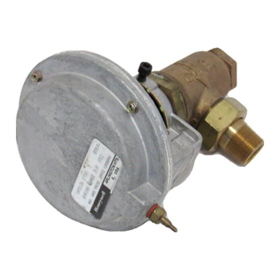
Sommaire des Matières pour Honeywell VP512A
- Page 1 Fig. 3. Reverse this procedure to replace the actuator. Refer to form 77-2301 (General Engineering Data for Pneumatic Control of Steam and Water Unit Ventilators) for the location of the VP512A in individual unit FLUID FLOW ventilators. ARROW EMBOSSED...
- Page 2 All manuals and user guides at all-guides.com VP512A UNIT VENTILATOR VALVE NEAREST OBSTRUCTION 5-1/8 (130) ALLOW 3-3/8 IN. 9 86 MM) APPROX FOR REMOVAL OF ACTUATOR FROM VALVE 7/16 (11) 3-5/8 STEM (92) H- SWING RADIUS BUTTON (TO TOP OF STEM...
- Page 3 FLÈCHE GRAVÉE SUR applications avec ventilo-convecteur séparé. LE CORPS DE VANNE MF18803 Fig. 1. Installation de la vanne (modèle à corps droit illustré). Tableau 1. Encombrement approximatif en mm (po) de la vanne VP512A. Dimension vanne Corps Droit 32 (1-1/4) √...
- Page 4 Fig. 3. Démontage de l'actionneur (si nécessaire). By using this Honeywell literature, you agree that Honeywell will have no liability for any damages arising out of your use or modification to, the literature. You will defend and indemnify Honeywell, its affiliates and subsidiaries, from and against any liability, cost, or damages, including attorneys’...


