Table des Matières
Publicité
Les langues disponibles
Les langues disponibles
Liens rapides
BEFORE INSTALLATION
CAUTION
Equipment Damage Hazard.
Use care in handling elements. A kinked capillary
renders the controller useless.
Whenever the capillary is bent, maintain a minimum
radius of 1 in. (25mm). Use a 1 to 3 in. (25 to 76mm)
pipe, a large screwdriver handle or a hammer handle to
achieve this radius.
Before connecting the air, blow main air from the line for
about one minute to clear and dry the line. Branch and
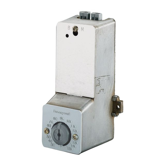
main barbs are clearly marked B and M. See Fig. 1. The
push on, sharp-barb connectors require no spring clips.
Fig. 1. Connector markings.
The controller is factory calibrated. It must be
recalibrated when the throttling range is changed from
factory settings.
Avoid hot supply lines with the plastic air piping. Refer to
Fig. 2 for the LP920 approximate dimensions.
® U.S. Registered Trademark
Copyright © 2002 Honeywell • All Rights Reserved
Remote Bulb Controller
INSTALLATION
Well-Mount Model
One bracket, two speed nuts and two no. 8 sheet metal
screws are furnished for securing the well-mounted
model. See Fig. 3.
1. Loosen the mounting bracket screws.
2. Remove one screw completely and swivel the
bracket to the side.
3. Put the sensing element into the well which is par-
tially filled with heat conductive compound (part no.
107408).
NOTE: The compound evenly distributes itself when
the sensing element is inserted.
4. Swivel the bracket back into position when the sen-
sor is fully into the well.
5. Secure so that the lip fits under the hex head of
the well.
6. Retighten the screws.
3-1/8
(80)
2-3/4
(70)
2-11/16
(68)
Fig. 2. LP920 approximate dimensions in in. (mm).
LP920A and B
INSTALLATION INSTRUCTIONS
5-9/16 (142)
2-1/4
(57)
M18367
95-7273EF
Publicité
Table des Matières

Sommaire des Matières pour Honeywell LP920A
- Page 1 Avoid hot supply lines with the plastic air piping. Refer to 2-11/16 Fig. 2 for the LP920 approximate dimensions. (68) M18367 Fig. 2. LP920 approximate dimensions in in. (mm). ® U.S. Registered Trademark Copyright © 2002 Honeywell • All Rights Reserved 95-7273EF...
- Page 2 LP920A AND B REMOTE BULB CONTROLLER ELEMENT LOCATED IN DUCT APPROXIMATELY 10 FEET (3M) HIGH. 1/2 NPT DUCT 1 IN. HEX HEAD CAPILLARY TO ELEMENT BRACKET NOMINAL DIMENSIONS LP920 WELLS LP920 MOUNTED TO COLUMN SENSOR DIMENSION WITH NO. 8 SCREWS WELL (IN.)
-
Page 3: Setpoint Adjustment
LP920A AND B REMOTE BULB CONTROLLER LP920B (REVERSE ACTING) IMPORTANT Remember to maintain the minimum 1 in. 1. BLP builds to within 1 psi (7 kPa) of main line pres- (25mm) bend radius. sure when setpoint knob is set at 150°F (66°C). -
Page 4: Calibration Procedure
DESCRIPTION LP920 Discharge Controller 315046B 7-3/8 IN. (187 MM) COPPER When using an LP920A in a heating system, a drop in 315904B 7-15/16 IN. (186 MM) STAINLESS STEEL temperature at the sensor lowers the branch line pressure. See Fig. 11. This opens the normally open valve further to increase the flow of heating medium to the coil. -
Page 5: Régulateur À Bulbe À Distance Lp920A Et B
1. Desserrer les vis sur le support de montage. Fig. 3. LP920 - Modèle à montage 2. Enlever une vis et tourner le support de côté. dans un doigt de gant. ® Marque de commerce déposée aux É.-U. Copyright © 2002 Honeywell • Tous droits réservés 95-7273EF... -
Page 6: Modèles À Montage En Gaine
RÉGULATEUR Ω BULBE Ω DISTANCE LP920A ET B Modèles à montage en gaine ÉLÉMENT DANS UNE GAINE DE 3 M (10 PI) DE HAUTEUR APPROX. MISE EN GARDE GAINE Risque de dommage matériel. Lors du choix de l'emplacement des modèles à montage en gaine, tenir compte de la limite de température... -
Page 7: Réglage De L'échelle Graduée
RÉGULATEUR Ω BULBE Ω DISTANCE LP920A ET B 2. La pression dans la prise de la canalisation secon- daire est réduite à moins de 7 kPa (1 psi) lorsque SUPPORT DE MONTAGE EN MÉTAL PERFORÉ (PIÈCE 2832) le bouton du point de consigne est réglé à 2 °C (35 °F). -
Page 8: Limiteurs Lp920A Et B
SERPENTIN MF18365 Fig. 11. LP920A - Régulateur d'air pulsé. By using this Honeywell literature, you agree that Honeywell will have no Solutions de régulation et d'automatisation liability for any damages arising out of your use or modification to, the Honeywell Honeywell Limited-Honeywell Limitée...


