
Manuels Connexes pour Lenze Drive PLC EPL-10200 Serie


Sommaire des Matières pour Lenze Drive PLC EPL-10200 Serie
- Page 1 All manuals and user guides at all-guides.com EDK10200EV3 00413774 Montageanleitung Mounting Instructions Instructions de montage Drive PLC...
- Page 2 all-guid es.com...
- Page 3 All manuals and user guides at all-guides.com Diese Dokumentation ist gültig für Drive PLC ab dem Gerätestand This documentation is only valid for Drive PLC as of version Se fascicule s’applique au Drive PLC à partir de la version : EPL - 10200 Drive PLC Hardwarestand...
- Page 4 All manuals and user guides at all-guides.com GLOBAL DRIVE d c b B A SH PRG 0003 00 PaR2 PaRa Par save LECOM A/B 59 39 71 72 88 89 plc007...
- Page 5 All manuals and user guides at all-guides.com Funktionskontrolle Drive PLC Die Verbindung zwischen PC und Drive PLC mit dem PC-Systembusmodul nur bei ausgeschalteten Geräten herstellen! +18 … 30 VDC / 0 V 120Ω 82plc017 Schritt Bemerkung siehe auch › € Kopierschutz-Dongle auf “Drive PLC Developer Studio - Erste Schritte”, Kap.
-
Page 6: Sicherheitshinweise
All manuals and user guides at all-guides.com Sicherheitshinweise Sicherheits- und Anwendungshinweise für Antriebsstromrichter 1. Für die Sicherheit verantwortliche Personen 3. Aufstellung Betreiber Die Aufstellung des Gerätes muß entsprechend den Vorschriften der zugehörigen Dokumentation erfolgen. Betreiber ist jede natürliche oder juristische Person, die die Drive PLC verwendet oder in deren Auftrag die Drive PLC verwendet wird. -
Page 7: Lieferumfang
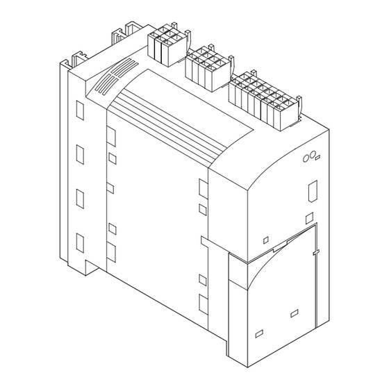
All manuals and user guides at all-guides.com Lieferumfang Abb. 1-1 plc004 › › 7 und 8 7 und 8 Klemmleiste X1: DC-Spannungsversorgung Klemmleiste X2: Digitale Ausgänge Klemmleiste X3: Digitale Eingänge › › Klemmleiste X4: Analoge Ein-/ Ausgänge 7 nd 9 7 und 9 Klemmleiste X5: Systembus (CAN) ›... - Page 8 all-guid es.com...
-
Page 9: Technische Daten
All manuals and user guides at all-guides.com Technische Daten Allgemeine Daten / Einsatzbedingungen Approbationen UL 508: Industrial Control Equipment (in Vorbereitung) DC-Spannungsversorgung DC Spannungsversorgung Spannung + 18 VDC ... 30 VDC Strom 200 mA bei + 24 V (ohne Belastung der Ausgänge) Umgebungstemperatur Umgebungstemperatur Transport... -
Page 10: Abmessungen Bei Standard-Befestigung
All manuals and user guides at all-guides.com Abmessungen bei Standard-Befestigung Abb. 1-2 4 Nm 35 lbin plc008 a [mm] a1 [mm] b [mm] b1 [mm] b2 [mm] c [mm] d [mm] e [mm] f [mm] EPL-10200 147 - 167 27.5 MA DrivePLC DE/EN/FR 1.1... -
Page 11: Emv-Gerechte Installation
All manuals and user guides at all-guides.com EMV-gerechte Installation 1 2 0 Abb. 1-3 plc013 Montageplatte mit elektrisch leitender Oberfläche. Leitungsschirm großflächig auf PE-Potential legen (PES: HF-Schirmabschluß durch PE-Anbindung). Beiliegende Befestigungsschellen verwenden. Signalleitung für analoge Ein- und Ausgangssignale. Leitung immer geschirmt verlegen. Signalleitung für Systembus (CAN), mit Busabschlußwiderstand (120 Ω). -
Page 12: Klemmleisten Verdrahten - Einfach Und Sicher
All manuals and user guides at all-guides.com Klemmleisten verdrahten - einfach und sicher Die mitgelieferten Klemmleisten sind geprüft nach den Spezifikationen der DIN VDE 0627:1986-06 (in Teilen) DIN EN 60999:1994-04 (in Teilen) Geprüft wurden u. a. mechanische, elektrische und thermische Beanspruchung, Vibration, Leiterbe- schädigung, Leiterlockerung, Korrosion und Alterung. -
Page 13: Klemmleisten - Übersicht
All manuals and user guides at all-guides.com Klemmleisten - Übersicht Abb. 1-5 plc001 Geräteansicht von oben DC-Spannungsversorgung Digitale Ausgänge Digitale Eingänge Geräteansicht von unten Analoge Ein-/ Ausgänge Systembus (CAN) MA DrivePLC DE/EN/FR 1.1... - Page 14 all-guid es.com...
- Page 15 All manuals and user guides at all-guides.com Steueranschlüsse Klemmleisten auf der Geräteoberseite Drive PLC nur an max. + 30 VDC Versorgungsspannung anschließen ! Höhere Spannung sowie Wechselspannung zerstört das Gerät ! … Abb. 1-6 X2 O1 O2 O3 O4 X1 +O24 +24 ƒ...
- Page 16 All manuals and user guides at all-guides.com Steueranschlüsse Klemmleisten auf der Geräteunterseite AI2 AI3 AOV AOI CAN-CG CAN-LO Abb. 1-7 CAN-HI plc003 Klemme Verwendung Pegel Daten Analoge Analoge X4/AI1 Frei belegbarer Eingang 1 Ei ä Eingänge X4/AI2 Frei belegbarer Eingang 2 -10 V ...
-
Page 17: Verdrahtung Systembus (Can)
All manuals and user guides at all-guides.com Verdrahtung Systembus (CAN) Drive PLC GND LOW 120Ω 120Ω plc014 Antriebsregler 1 Antriebsregler 2 PES HF-Schirmabschluß durch PE-Anbindung Verbinden Sie nur Klemmen gleicher Bezeichnung miteinander Eigenschaften Signalleitung: Leitungslänge gesamt bis 300 m 300 bis 1000 m Leitungstyp Leitungstyp LIYCY 2 x 2 x 0,5 mm... -
Page 18: Montage Funktionsmodul (Option)
All manuals and user guides at all-guides.com Montage Funktionsmodul (Option) Abb. 1-8 plc006 1. Schutzkappe entfernen und aufbewahren. 2. Funktionsmodul auf die FIF-Schnittstelle stecken. 3. Verdrahtung: siehe Montageanleitung des Funktionsmoduls. MA DrivePLC DE/EN/FR 1.1... -
Page 19: Montage Kommunikationsmodul (Option)
All manuals and user guides at all-guides.com Montage Kommunikationsmodul (Option) GLOBAL DRIVE d c b B A SH PRG 0003 00 PaR2 PaRa Par save Abb. 1-9 LECOM A/B 59 39 71 72 88 89 plc016 Automatisierungs-Interface (AIF) Das Automatisierungs-Interface (AIF) dient dem Anschluß verschiedener Aufsteckmodule: Keypad E82ZBC (8200 vector) oder 9371BB (9300) Feldbusmodule –... - Page 20 all-guid es.com...
-
Page 21: Montage Extension Board (Option)
All manuals and user guides at all-guides.com Montage Extension Board (Option) Abb. 1-10 plc015 1. Schutzkappe entfernen und aufbewahren. 2. Stiftleisten auf das Extension Board einsetzen. 3. Extension Board in die Drive PLC einsetzen. 4. Verdrahtung: siehe Montageanleitung des Extension Board. MA DrivePLC DE/EN/FR 1.1... - Page 22 Einschalten Start, Stop, Reset Start, Stop, Reset Keypad 9371BB (9300) Keypad 9371BB (9300) C2108 = -0- Funktion ausgeführt C2108 = -1- Programm starten C2108 = -2- Programm stoppen C2108 = -3- Programm zurücksetzen Lenze-Einstellung MA DrivePLC DE/EN/FR 1.1...
- Page 23 Die Software “Global Drive Control Light” ist auf der CD-ROM “Drive PLC Developer Studio” enthalten. Die Vollversion von “Global Drive Control” erhalten Sie bei Lenze unter der Bestellnummer ESP-GDC 1. Eine Beschreibung zum Parametrieren mit dem Keypad finden Sie in der Anleitung, die jedem Keypad beiliegt.
- Page 24 All manuals and user guides at all-guides.com Störungen erkennen und beseitigen Fehlverhalten der Drive PLC Abb. 1-12 Fehlverhalten Ursache Abhilfe Kommunikationsfehler Kommunikationsfehler Drive PLC ohne Versorgungsspannung Versorgungsspannung einschalten › Ei l Einloggen nicht möglich ö li h Keine Verbindung zwischen PC und Drive PLC Verdrahtung des Systembus prüfen ›...
-
Page 25: Störungen Erkennen Und Beseitigen
Externe Störung (TRIP-Set) Ein mit der Funktion TRIP-Set beleg- Externen Geber überprüfen tes digitales Signal ist aktiviert wor- Interne Störung Rücksprache mit Lenze erforderlich Fehler im Programmablauf Es wurde ein Fehler im Programm- Drive PLC mit Datensatz (auf Dis- ablauf festgestellt. - Page 26 all-guid es.com...
- Page 27 All manuals and user guides at all-guides.com Function control Drive PLC Make the connection between the PC and Drive PLC and the PC system bus module ONLY when the equipment is switched off ! +18 … 30 VDC / 0 V 120Ω...
-
Page 28: Safety Information
All manuals and user guides at all-guides.com Safety information Safety and application notes for controllers 1. Persons responsible for safety 3. Installation Operator The units must be installed according to the regulations given in the corresponding documentation. The operator is any natural or judicial person, who uses the Drive PLC or in whose name the Drive PLC is used. -
Page 29: Items Supplied
All manuals and user guides at all-guides.com Items supplied Abb. 1-13 plc004 › › 7 and 8 7 and 8 Terminal strip X1: DC-supply voltage Terminal strip X2: digital outputs Terminal strip X3: digital inputs › › Terminal strip X4: analog inputs and outputs 7 and 9 7 and 9 Terminal strip X5: system bus (CAN) -
Page 30: Technical Data
All manuals and user guides at all-guides.com Technical data General data / Application conditions Approvals UL 508: Industrial Control Equipment (in preparation) DC voltage supply DC voltage supply Voltage + 18 VDC ... 30 VDC Current 200 mA at + 24 V (without load at the outputs) Ambient temperature Ambient temperature transport... -
Page 31: Dimensions For Standard Fixing
All manuals and user guides at all-guides.com Dimensions for standard fixing Abb. 1-14 4 Nm 35 lbin plc008 a [mm] b [mm] b1 [mm] b2 [mm] c [mm] d [mm] e [mm] f [mm] [mm] EPL-10200 147 - 167 27.5 MA DrivePLC DE/EN/FR 1.0... - Page 32 all-guid es.com...
-
Page 33: Installation According To Emc
All manuals and user guides at all-guides.com Installation according to EMC 1 2 0 Abb. 1-15 plc013 Mounting plate with electrically conductive surface. Ground the cable screen with a large-area connection to PE (PES: HF screen connection via PE connection). Use the enclosed fixing brackets. -
Page 34: Terminal Strip Wiring - Easy And Safe
All manuals and user guides at all-guides.com Terminal strip wiring - easy and safe The terminal strips that are supplied have been tested to the specifications of DIN VDE 0627:1986-06 (in parts) DIN EN 60999:1994-04 (in parts) Features tested, amongst others, are: mechanical , electrical and thermal stress, vibration, damage to conductors, loose conductors, corrosion and ageing. -
Page 35: Terminal Strips - Overview
All manuals and user guides at all-guides.com Terminal strips - overview Abb. 1-17 plc001 Instrument seen from above DC voltage supply Digital outputs Digital inputs Instrument seen from below Analog inputs/outputs System bus (CAN) MA DrivePLC DE/EN/FR 1.0... -
Page 36: Control Connections
All manuals and user guides at all-guides.com Control connections Terminal strips on the top of the instrument The Drive PLC can only be connected to a supply voltage of max. + 30 V DC ! Higher voltages, or AC, will destroy the instrument ! …... - Page 37 All manuals and user guides at all-guides.com Control connections Terminal strips on the bottom of the instrument AI2 AI3 AOV AOI CAN-CG CAN-LO Abb. 1-19 CAN-HI plc003 Terminal Use level Data Analog Analog X4/AI1 Freely assignable input 1 inputs X4/AI2 Freely assignable input 2 -10 V ...
- Page 38 all-guid es.com...
-
Page 39: System Bus (Can) Wiring
All manuals and user guides at all-guides.com System bus (CAN) wiring Drive PLC GND LOW 120Ω 120Ω plc014 Controller 1 Controller 2 PES HF screen termination through PE connection Only connect terminals of the same designation. Features of the system cable: Total cable length up to 300 m 300 to 1000 m... -
Page 40: Function Module Mounting (Option)
All manuals and user guides at all-guides.com Function module mounting (option) Abb. 1-20 plc006 1. Remove and store protective cover 2. Plug function module on FIF interface. 3. Wiring: See Mounting Instructions of the function module. MA DrivePLC DE/EN/FR 1.0... -
Page 41: Communication Module Mounting (Option)
All manuals and user guides at all-guides.com Communication module mounting (option) GLOBAL DRIVE d c b B A SH PRG 0003 00 PaR2 PaRa Par save Abb. 1-21 LECOM A/B 59 39 71 72 88 89 plc016 Automation interface (AIF) The automation interface (AIF) is used for the connection of different plug-on modules Keypad E82ZBC (8200 vector) or 9371BB (9300) Fieldbus modules... -
Page 42: Extension Board Mounting (Option)
All manuals and user guides at all-guides.com Extension Board mounting (option) Abb. 1-22 plc015 1. Remove and store the protective cover 2. Insert the pin connector strip on the Extension Board 3. Insert the Extension Board into the Drive PLC. 4. - Page 43 Start, Stop, Reset Start, Stop, Reset Keypad 9371BB (9300) Keypad 9371BB (9300) C2108 = -0- Function executed C2108 = -1- Start program C2108 = -2- Stop program C2108 = -3- Reset program Lenze setting MA DrivePLC DE/EN/FR 1.0...
- Page 44 all-guid es.com...
- Page 45 The software “Global Drive Control Light” is included on the CD-ROM “Drive PLC Developer Studio”. The full version of “Global Drive Control” can be obtained from Lenze, with ordering number ESP-GDC 1. A description of parameterization with the keypad can be found in the instructions that are supplied with every keypad.
- Page 46 All manuals and user guides at all-guides.com Troubleshooting and fault elimination Fault response of the Drive PLC Abb. 1-24 Malfunction Cause Remedy Communication error Communication error Drive PLC has no supply voltage Switch on supply voltage › Log-in not possible No connection between PC and Drive PLC Check system bus wiring ›...
-
Page 47: Troubleshooting And Fault Elimination
Drive PLC. Parameter set does not match Drive PLC Internal fault Contact Lenze Wrong PAR1 transfer when using PAR1 is defective. Repeat data transfer or load Lenze the keypad/PC. settings Internal fault Contact Lenze LECOM fault number MA DrivePLC DE/EN/FR 1.0... -
Page 48: Contrôle Fonctionnel Drive Plc
All manuals and user guides at all-guides.com Contrôle fonctionnel Drive PLC Vérifier que les appareils sont hors tension lors de la liaison PC-Drive PLC par le module bus système +18 … 30 VDC / 0 V 120Ω 82plc017 Etape Remarque Voir aussi ›... -
Page 49: Consignes De Sécurité
All manuals and user guides at all-guides.com Consignes de sécurité Instructions générales de sécurité et d’emploi relatives aux variateurs de vitesse 1. Consignes destinées aux responsables de la 3. Installation sécurité L’installation de l’appareil doit répondre aux prescriptions de la documentation fournie avec le produit. - Page 50 all-guid es.com...
-
Page 51: Equipement Livré
All manuals and user guides at all-guides.com Equipement livré Abb. 1-25 plc004 › › 7 et 8 7 et 8 Bornier X1 : Alimentation CC Bornier X2 : Sorties numériques Bornier X3 : Entrées numériques › › Bornier X4 : Entrées/sorties analogiques 7 et 9 7 et 9 Bornier X5 : Bus système (CAN) -
Page 52: Spécifications Techniques
All manuals and user guides at all-guides.com Spécifications techniques Caractéristiques générales/conditions ambiantes Homologations UL 508 Industrial Control Equipment (équipement de régulation industrielle) (en préparation) Alimentation CC Alimentation CC Tension + 18 VCC ... 30 VCC Courant 200 mA pour + 24 V (sans charge sur les sorties) Température ambiante Température ambiante Transport... -
Page 53: Encombrements Dans Le Cas D'une Fixation Standard
All manuals and user guides at all-guides.com Encombrements dans le cas d’une fixation standard Abb. 1-26 4 Nm 35 lbin plc008 a [mm] a1 [mm] b [mm] b1 [mm] b2 [mm] c [mm] d [mm] e [mm] f [mm] EPL-10200 147 - 167 27,5 MA DrivePLC DE/EN/FR 1.0... -
Page 54: Installation Conforme Cem
All manuals and user guides at all-guides.com Installation conforme CEM 1 2 0 Abb. 1-27 plc013 Plaque de montage avec surface conductrice Relier le blindage par une surface importante avec le potentiel PE (PES : Terminaison blindage HF par raccordement PE). Utiliser les colliers de fixation compris dans l’emballage. -
Page 55: Raccordement Des Borniers - Simple Et Sûr
All manuals and user guides at all-guides.com Raccordement des borniers - simple et sûr Les borniers compris dans la livraison ont été vérifiés conformément aux normes et réglementations suivantes : DIN VDE 0627 : 1986-06 (en partie) DIN EN 60999 : 1994-04 (en partie) Les borniers ont été... - Page 56 all-guid es.com...
- Page 57 All manuals and user guides at all-guides.com Borniers - schéma Abb. 1-29 plc001 Vue par-dessus Alimentation CC Sorties numériques Entrées numériques Vue par-dessous Entrées/sorties analogiques Bus système (CAN) MA DrivePLC DE/EN/FR 1.0...
-
Page 58: Borniers De Commande
All manuals and user guides at all-guides.com Borniers de commande Borniers sur la face supérieure Raccorder le Drive PLC seulement à l’alimentation + 30 VCC maxi ! Toute tension supérieure et toute tension alternative entraîneront une destruction de l’appareil ! …... - Page 59 All manuals and user guides at all-guides.com Borniers de commande Borniers sur la face inférieure AI2 AI3 AOV AOI CAN-CG CAN-LO Abb. 1-31 CAN-HI plc003 Bornes Fonction Niveau Données Entrées Entrées X4/AI1 Entrée programmable 1 analogiques X4/AI2 Entrée programmable 2 -10 V ...
-
Page 60: Câblage Bus Système (Can)
All manuals and user guides at all-guides.com Câblage bus système (CAN) Drive PLC GND LOW 120Ω 120Ω plc014 Variateur de vitesse 1 Variateur de vitesse 2 PES Terminaison blindage HF par raccordement PE Ne relier que les bornes de désignation identique. Caractéristiques câbles signaux : Longueur totale Jusqu’à... -
Page 61: Montage Module De Fonction (Option)
All manuals and user guides at all-guides.com Montage module de fonction (option) Abb. 1-32 plc006 1. Enlever le capot de protection (ne pas le jeter). 2. Enficher le module de fonction dans l’interface FIF. 3. Câblage : Voir instruction de montage du module de fonction. MA DrivePLC DE/EN/FR 1.0... - Page 62 all-guid es.com...
-
Page 63: Montage Module De Communication (Option)
All manuals and user guides at all-guides.com Montage module de communication (option) GLOBAL DRIVE d c b B A SH PRG 0003 00 PaR2 PaRa Par save Abb. 1-33 LECOM A/B 59 39 71 72 88 89 plc016 Interface d’automatisme (AIF) L’interface d’automatisme (AIF) permet de raccorder différents modules débrochables. -
Page 64: Montage Module Extension Bornier (Option)
All manuals and user guides at all-guides.com Montage module extension bornier (option) Abb. 1-34 plc015 1. Enlever le capot de protection (ne pas le jeter). 2. Enficher les connecteurs à broches dans le module Extension bornier 3. Enficher le module extension bornier dans le Drive PLC. -
Page 65: Mise En Service
Marche, arrêt, Marche, arrêt, C2108 = -0- Fonction exécutée 9371BB (9300) 9371BB (9300) réarmement é C2108 = -1- Lancer le programme. C2108 = -2- Arrêter le programme. C2108 = -3- Remise à zéro du programme Réglage Lenze MA DrivePLC DE/EN/FR 1.0... - Page 66 Le cédérom “Drive PLC Developer Studio” comprend le logiciel “Global Drive Control Light”. La version complète de “Global Drive Control” est disponible sur demande (référence de commande Lenze ESP-GDC 1). Le paramétrage via clavier est décrit dans les instructions de mise en service du clavier (comprises dans l’emballage).
- Page 67 All manuals and user guides at all-guides.com Détection et élimination les défauts Anomalie de fonctionnement du Drive PLC Abb. 1-36 Anomalie de fonctionnement Origine Remède Erreur de communication Erreur de communication Drive PLC sans tension d’alimentation Brancher la tension d’alimentation. ›...
- Page 68 all-guid es.com...
-
Page 69: Détection Et Élimination Les Défauts
Un signal numérique affecté de la Vérifier le codeur externe. fonction ”mise en défaut”(TRIP-Set) a été activé. Défaut interne Contacter votre service Lenze. Erreur dans le déroulement du Une erreur a été constatée dans le Renvoyer le Drive PLC avec jeu de programme déroulement du programme.