Table des Matières
Publicité
Les langues disponibles
Les langues disponibles
Liens rapides
Betriebsanleitung
Stratos®Pro
Bedienungsanleitung
Temperatur-Meßumformer . . . . . . . . . .
Instructions for Use
Temperature Transmitters. . . . . . . . . .
Mode d'emploi
Convertisseurs de température . . . .
Aktuelle Produktinformation:
Aktuelle Produktinformation: www.knick.de
ThermoTrans®
Stratos Pro A2... pH
deutsch
P32100P0/11-KTA
Betriebsanleitung
The Art of Measuring.
A2... PH
3
35
67
BVS 10 ATEX E089 X
II 1G Ex ia IIC T3/T4/T6
14163 Berlin
SE 706X/1-NMSN
BVS 10 ATEX E089 X
II 1G Ex ia IIC T3/T4/T
14163 Berlin
SE 706X/2-NMSN
BVS 10 ATEX E089 X
II 1G Ex ia IIC T3/T4/T
www.knick.de
14163 Berlin
SE 706X/2-NM
14163 Berlin
BVS 10 ATEX E
SE 706X/1-NM
II 1G Ex ia IIC
BVS 10 ATEX
II 1G Ex ia IIC
14163 Berlin
SE 706X/2-NM
BVS 10 ATEX
II 1G Ex ia IIC
Publicité
Chapitres
Table des Matières

Manuels Connexes pour Knick ThermoTrans P32100P0/11-KTA


Sommaire des Matières pour Knick ThermoTrans P32100P0/11-KTA
- Page 1 Temperatur-Meßumformer ..Instructions for Use Temperature Transmitters..Mode d‘emploi Convertisseurs de température ..www.knick.de Aktuelle Produktinformation: Aktuelle Produktinformation: www.knick.de...
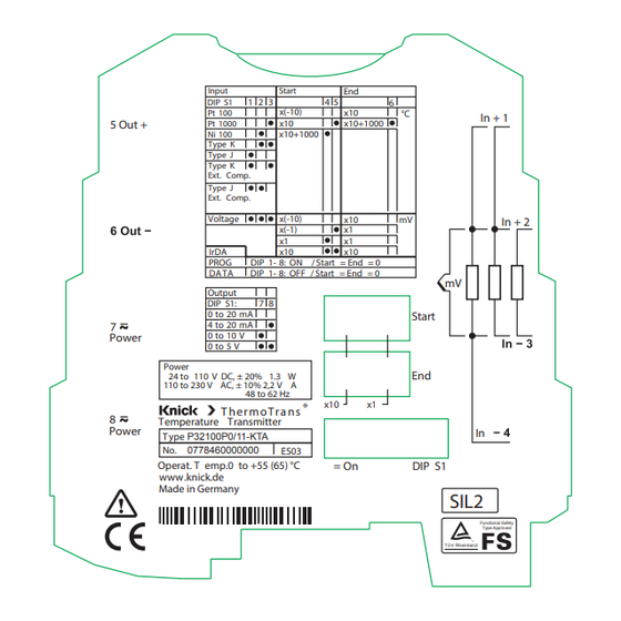
- Page 3 T her mo T r a ns Temperature Transmitter Power T ype P32100P0/11-KTA 0778460000000 ES03 Operat. T emp.0 to +55 (65) °C = On DIP S1 www.knick.de Made in Germany SIL2 Functional Safety Type Approved ® Rheinland T Ü V www.knick.de...
-
Page 4: Garantie
Garantie Garantie Innerhalb von 5 Jahren ab Lieferung auftretende Mängel werden bei freier Anlieferung im Werk kostenlos behoben. Zubehör: 1 Jahr. Änderungen vorbehalten. Rücksendung Kontaktieren Sie das Service-Team, Kontaktdaten siehe Rückseite. Senden Sie das Gerät gereinigt an die Ihnen genannte Adresse. Entsorgung Die landesspezifischen gesetzlichen Vorschriften für die Entsorgung von “Elektro/Elektronik-Altgeräten”... -
Page 5: Table Des Matières
Inhaltsverzeichnis Garantie .................... 4 Sicherheitshinweise ............... 7 Bestimmungsgemäßer Gebrauch ..........8 Prinzipschaltbild ................... 8 Funktion ................... 9 3-Port-Trennung der Eingänge, Ausgänge und Stromversorgung ................. 9 Montage und elektrischer Anschluß ........10 Maßzeichnung und Schaltelemente ..........10 Meßbereiche .................11 Ausgangs nennbereich ..............11 Verhalten des Ausgangsstroms (4 ... 20 mA) bei Meßbereichsüber- bzw. - Page 6 Inhaltsverzeichnis Technische Daten .................23 Eingangsdaten Widerstandsthermometer (RTD) ....23 Eingangsdaten Thermoelemente (TC) ........24 Eingangsdaten Shuntspannung (Voltage) .......25 Ausgangsdaten ...................26 Übertragungsverhalten ..............27 Hilfsenergie ..................27 Isolation ....................27 Normen und Zulassungen ..............28 weitere Daten ..................29 Bestelldaten ...................30...
-
Page 7: Sicherheitshinweise
Sicherheitshinweise Warnung! Schutz gegen gefährliche Körperströme Bei Anwendungen mit hohen Arbeitsspannungen ist auf genügend Abstand bzw. Isolation zu Nebengeräten und auf Berührungsschutz zu achten. Achtung! Beim Umgang mit den Bausteinen ist auf Schutzmaßnah- men gegen elektrostatische Entladung (ESD) zu achten. Achtung! Die Universal-Meßumformer PolyTrans®... -
Page 8: Bestimmungsgemäßer Gebrauch
Bestimmungsgemäßer Gebrauch Die Temperatur-Meßumformer ThermoTrans® P32100P0/11-KTA bie- ten Anschlußmöglichkeiten für alle gängigen Thermoelemente und Widerstandsmeßfühler. Bei Widerstandsmeßfühlern wird die Anschlußkonfiguration 2-, 3- oder 4-Leiterschaltung beim Gerätestart automatisch erkannt. Das Ausgangssignal ist einstellbar auf 0 / 4 ... 20 mA oder 0 ... 5 / 10 V. Die Umschaltung der Meßbereiche erfolgt kalibriert über DIP- und Drehcodierschalter. -
Page 9: Funktion
Funktion Der Temperatur-Meßumformer tastet Signale von Thermoelementen,bzw. Widerstandsmeßfühlern periodisch ab und formt den Abtastwert in ein dem Meßwert proportionales Ausgangssi- gnal um. Das Ausgangssignal kann als Spannungs- oder Stromsignal ausgege- ben werden. Eine 3-Port-Trennung mit sicherer Trennung nach EN 61140 bis zu 300 VAC/DC garantiert Personen- und Anlagenschutz sowie eine unverfälschte Übertragung der Meßsignale. -
Page 10: Montage Und Elektrischer Anschluß
Montage und elektrischer Anschluß Die Meßumformer werden auf TS 35 Normschienen aufgerastet und seitlich durch geeignete Endwinkel fixiert. Klemmenbelegung siehe Maßzeichnung. Anschlußquerschnitt: 0,2 mm ... 2,5 mm (AWG 24-14). Maßzeichnung und Schaltelemente Bedienöffnung für Taster Betriebs-LED (grün) Status-LED (gelb) Melde-LED (rot) Taster Eingang 1 + Startwert (2 Drehcodierschalter) -
Page 11: Meßbereiche
Meßbereiche Der Meßumformer kann das Eingangssignal in ein Strom- oder Span- nungssignal umwandeln („Ausgangsnennbereich“): 0 ... 5 V 0 ... 10 V 0 ... 20 mA 4 ... 20 mA Dabei wird der eingestellte Start-Wert des Meßbereichs (siehe S. 18) auf den Anfang des Ausgangsnennbereichs und der End-Wert auf das Ende des Ausgangsnennbereichs abgebildet. -
Page 12: Verhalten Des Ausgangsstroms (4
Meßbereiche Verhalten des Ausgangsstroms (4 ... 20 mA) bei Meßbereichsüber- bzw. -unterschreitung 21,0 20,5 Eingang Startwert Endwert... -
Page 13: Beschaltungsvarianten (Sensoranschluß)
Beschaltungsvarianten (Sensoranschluß) ThermoTrans P32100P0/11-KTA Einstellbar über: Sensor Anschluß Abbildung IrDA Schal- Pt100 2-, 3- oder 4-Leiter , 1, 2, 3 automatische Erkennung 2-, 3-, 4-Leiter oder Differenz, 1, 2, 3, 6 fest eingestellt Pt1000 2-, 3- oder 4-Leiter , 1, 2, 3... - Page 14 Beschaltungsvarianten Anschluß von Widerstandsthermometern RTD: RTD: RTD: 4-Leiter 3-Leiter 2-Leiter Mit Hilfe der Software Paraly 111 kann der volle Funktionsumfang des Meßumformers parametriert wer- den. Beschaltungsbeispiele mit grau hinterlegter Abbildungsnummer sind nur über IrDA einstellbar.
- Page 15 Beschaltungsvarianten Anschluß von Widerstandsthermometern / Thermoelementen RTD Differenz: Differenz Diff Diff Ext. Kaltstellen- TC Summen- kompensation schaltung Pt 100 Mit Hilfe der Software Paraly 111 kann der volle Funktionsumfang des Meßumformers parametriert wer- den. Beschaltungsbeispiele mit grau hinterlegter Abbildungsnummer sind nur über IrDA einstellbar.
-
Page 16: Anschluß Bei Spannungsmessung
Beschaltungsvarianten Anschluß bei Spannungsmessung Spannung Shunt Mit Hilfe der Software Paraly 111 kann der volle Funktionsumfang des Meßumformers parametriert wer- den. Beschaltungsbeispiele mit grau hinterlegter Abbildungsnummer sind nur über IrDA einstellbar. -
Page 17: Anschluß Thermoelement (Summenschaltung)
Beschaltungsvarianten Anschluß Thermoelement (Summenschaltung) TC Summenschaltung Hinweis: In Summenschaltung können maximal 10 Thermoelemente ange- schlossen werden. Mit Hilfe der Software Paraly 111 kann der volle Funktionsumfang des Meßumformers parametriert wer- den. Beschaltungsbeispiele mit grau hinterlegter Abbildungsnummer sind nur über IrDA einstellbar. -
Page 18: Konfigurierung Über Schalter
Konfigurierung über Schalter Stellen Sie die DIP- und Drehcodierschalter gemäß Tabelle (Gehäuse- aufdruck) ein. Sensortyp: Angeschlossenen Sensor über Schalter DIP1 bis DIP3 einstellen. Startwert: Stellen Sie den Ziffernwert (00 ... 99) mit Hilfe der Drehkodierschalter „Start“ ein. Über die Schalter DIP4, DIP5 stellen Sie den Faktor ein. Eine fallende Kennlinie wird durch die Einstellung Startwert größer Endwert realisiert. -
Page 19: Kommunikation Über Irda-Schnittstelle
Parameter des Meßumformers (siehe Tabelle auf Seite 13). Die Softwa- re wird mit einer detaillierten Anleitung ausgeliefert, welche auch als Download auf der Website „www.knick.de“ zur Verfügung steht. Erweiterte Funktionsmerkmale des Universal-Meßumformers durch Kommunikation über die Software „Paraly SW 111“:... -
Page 20: Konfigurierung Über Schalter: Funktionsübersicht
Konfigurierung über Schalter: Funktionsübersicht = DIP-Schalter ON... -
Page 21: Konfigurierung Über Schalter: Beispiel
Konfigurierung über Schalter: Beispiel Sensor: Thermoelement Typ J Meßbereich: 200 ... 1200 °C Ausgangssignal: 4 - 20 mA 1. Sensortyp einstellen: TC Typ J: DIP1 = 1, DIP2 = 0, DIP 3 = 0 2. Startwert einstellen: 200 °C Dieser Startwert setzt sich zusammen: Ziffernwert = 20, Faktor = x10. Ziffernwert mit Drehkodierschaltern einstellen: Dazu Faktor x10 einstellen: DIP4 = 0, DIP5 = 1... -
Page 22: Led Und Fehlersignalisierung Am Gerät
LED und Fehlersignalisierung am Gerät Hinweis: Grüne und rote LED blinken beim Gerätestart kurz auf. grün: Versorgungsspannung vorhanden gelb: Beim Start einmalige Signalisierung der erkannten Anschlußart bei RTD-Messung (2-/3-/4-maliges Blinken entspricht 2-/3-/4-Leitermessung) Blinken: IrDA aktiv Dauerlicht: IrDA verbunden rot: Fehlerstatus; die LED blinkt mit der Anzahl der Fehlernummer Ausgang [mA] Ausgang [V] Nr. -
Page 23: Technische Daten
Technische Daten Eingangsdaten Widerstandsthermometer (RTD) Gebertyp (Norm) Meßbereich [°C] Pt100 (DIN 60751) - 200 ... 850 Pt1000 (DIN 60751) - 200 ... 850 Ptxxx (DIN 60751) - 200 ... 850 Ni100 (DIN 43760) - 60 ... 180 Nixxx (DIN 43760) - 60 ... -
Page 24: Eingangsdaten Thermoelemente (Tc)
Technische Daten Eingangsdaten Thermoelemente (TC) Gebertyp (Norm) Meßbereich [°C] nur über IrDA wählbar (DIN 60584-1) 250 ... 1820 (DIN 60584-1) - 200 ... 1000 (DIN 60584-1) - 210 ... 1200 (DIN 60584-1) - 200 ... 1372 (DIN 43710) - 200 ... 900 (DIN 60584-1) - 200 ... -
Page 25: Eingangsdaten Shuntspannung (Voltage)
Technische Daten Eingangsdaten Shuntspannung (Voltage) Eingang - 1000 ... 1000 mV unipolar/bipolar Eingangswiderstand > 10 MΩ Eingangsfehlergrenzen ± (200 µV + 0,05 % v.M.) für Meßspannen > 50 mV Leitungsüberwachung Leitungsbruch Temperaturkoeffizient am 50 ppm/K vom konfigurierten Meß- Eingang bereichsendwert (mittlerer Tk im zu- lässigen Betriebstemperaturbereich, Referenztemperatur 23 °C) Überlastbarkeit... -
Page 26: Ausgangsdaten
Technische Daten Ausgangsdaten Ausgänge 0 ... 20 mA, 4 ... 20 mA, 0 ... 10 V oder 0 ... 5 V, kalibriert umschaltbar Aussteuerbereich 0 % bis ca. 102,5 % der Meßspanne bei 0 ... 20 mA, 0 ... 10 V bzw. 0 ... -
Page 27: Übertragungsverhalten
Technische Daten Übertragungsverhalten Kennlinie Linear steigend / fallend; über IrDA: parametrierbare Kennlinie mit Stütz- stellen oder über Polynome Meßrate ca. 3 / s ca. 2 / s im Betriebsmodus, Thermoelement mit ext. Vergleichs- stellenkompensation Einstellzeit t 99* 300 ms 500 ms im Betriebsmodus, Thermoelement mit ext. -
Page 28: Normen Und Zulassungen
Technische Daten Schutz gegen gefährliche Sichere Trennung nach DIN EN 61140 (VDE 0140 Teil 1) durch verstärkte Isolie- Körperströme rung gemäß DIN EN 61010-1 (VDE 0411 Teil 1). Arbeitsspannung bis zu 300 V AC/ DC bei Überspannungskategorie II und Verschmutzungsgrad 2 zwischen allen Kreisen. -
Page 29: Weitere Daten
Technische Daten weitere Daten Umgebungstemperatur bei Betrieb 0 ... + 65 °C Einzelgerät mit Abstand > 6 mm zu Nachbargeräten 0 ... + 55 °C (angereihter Zustand; Die Geräte werden unter Verwendung der Zwischenstücke ZU0784 montiert) bei Lagerung - 25 ... + 85 °C Umgebungsbedingungen Ortsfester Einsatz, wettergeschützt rel. -
Page 30: Bestelldaten
Bestelldaten Bestellnr. Universal-Meßumformer, einstellbar P32100P0/11-KTA Zubehör Bestellnr. ® Kommunikations-Software Paraly SW 111 SW111... - Page 35 T her mo T r a ns Temperature Transmitter Power T ype P32100P0/11-KTA 0778460000000 ES03 Operat. T emp.0 to +55 (65) °C = On DIP S1 www.knick.de Made in Germany SIL2 Functional Safety Type Approved ® Rheinland T Ü V www.knick.de...
- Page 36 Warranty Warranty Defects occurring within 5 years from delivery date shall be remedied free of charge at our plant (carriage and insurance paid by sender). Accessories: 1 year. Subject to change without notice. Return of products Please contact our Service Team before returning a defective device (see back cover for contact details).
- Page 37 Table of Contents Warranty ..................36 Safety Information ...............39 Intended Use .................40 Block diagram ..................40 Function ..................41 3-port isolation of inputs, outputs and power supply ..41 Mounting and Electrical Connection ........42 Dimension drawing and control elements.......42 Measuring Ranges ................43 Nominal output range ..............43 Response of output current (4 ...
- Page 38 Table of Contents Specifications ................55 Input data for resistance thermometer (RTD) ......55 Input data for thermocouple (TC) ..........56 Input data for shunt (voltage) ............57 Output data..................58 Response ....................59 Power supply ..................59 Isolation ....................59 Standards and approvals ..............60 Other data ....................61 Order Information ................62...
-
Page 39: Safety Information
Safety Information Warning! Protection against electric shock For applications with high working voltages, ensure there is sufficient spacing or isolation from neighboring devices and protection against electric shocks. Caution! Be sure to take protective measures against electrostatic discharge (ESD) when handling the devices! Caution! P32100P0/11-KTA The PolyTrans®... -
Page 40: Intended Use
Intended Use The ThermoTrans® P32100P0/11-KTA temperature transmitters provide connection possibilities all common thermocouples and resistance thermometers. When a resistive sensor is connected, 2-, 3-, or 4-wire configuration is automatically recognized at device startup. The output signal is adjustable to 0 / 4 ... 20 mA, or 0 … 5 / 10 V. The calibrated range selection is performed using DIP and rotary coding switches. -
Page 41: Function
Function The temperature transmitter periodically samples signals from thermocouples or resistance thermometers. These signals are converted into output signals proportional to the measured values. The output signal can be a voltage or a current. 3-port isolation with Safe Isolation up to 300 V AC/DC according to EN 61140 ensures optimum protection of personnel and equipment as well as unaltered transmission of measuring signals. -
Page 42: Mounting And Electrical Connection
Mounting and Electrical Connection The transmitters are snapped onto TS 35 standard rails and laterally fixed by suitable end brackets. See dimension drawing for terminal as- signments. Conductor cross-section: 0.2 mm ... 2.5 mm (AWG 24-14). Dimension drawing and control elements Hole for pushbutton Operation LED (green) Status LED (yellow) -
Page 43: Measuring Ranges
Measuring Ranges The transmitter can convert the input signal into a current or voltage signal ("nominal output range"): 0 ... 5 V 0 ... 10 V 0 ... 20 mA 4 ... 20 mA The start value adjusted for the measuring range (see Pg 50) is repre- sented by the lower limit of the nominal output range. -
Page 44: Response Of Output Current (4
Measuring Ranges Response of output current (4 ... 20 mA) to out-of-range conditions 21.0 20.5 Input Start value End value... -
Page 45: Wiring Possibilities (Sensor Connection)
Wiring Possibilities (Sensor Connection) ThermoTrans P32100P0/11-KTA Adjustable via: Sensor Type Connection Figure IrDA Switch Pt100 2-, 3- or 4-wire, 1, 2, 3 automatic recognition 2-, 3- 4-wire or differential, 1, 2, 3, 6 fixed setting Pt1000 2-, 3- or 4-wire,... - Page 46 Wiring Possibilities Connection of resistance thermometers RTD: RTD: RTD: 4-wire 3-wire 2-wire You can configure all functions of the transmitter using the Paraly SW 111 software. Wirings with a shaded number can only be adjusted via IrDA.
-
Page 47: Configuration
Wiring Possibilities Connection of resistance thermometers / thermocouples RTD difference: difference: Diff Diff Ext. cold junction TC summing compensation configuration Pt 100 You can configure all functions of the transmitter using the Paraly SW 111 software. Wirings with a shaded number can only be adjusted via IrDA. -
Page 48: Connection For Voltage Measurement
Wiring Possibilities Connection for voltage measurement Voltage Shunt You can configure all functions of the transmitter using the Paraly SW 111 software. Wirings with a shaded number can only be adjusted via IrDA. -
Page 49: Connection Of Thermocouple (Summing Configuration)
Wiring Possibilities Connection of thermocouple (summing configuration) TC summing configuration Please note: You can only connect up to 10 thermocouples in summing configuration. You can configure all functions of the transmitter using the Paraly SW 111 software. Wirings with a shaded number can only be adjusted via IrDA. -
Page 50: Configuration Using Switches
Configuration using Switches Adjust the DIP and rotary switches according to the table on the housing. Sensor type: Select the connected sensor type using switches DIP1 to DIP3. Start value: Adjust the number (00 ... 99) using the "Start“ rotary switches. Adjust the factor using the switches DIP4, DIP5. -
Page 51: Communication Via Irda Interface
PC or PDA. It allows configuring all transmitter parameters (see table on Pg 45). The software comes with detailed instructions which are also available for download at "www.knick.de". Additional functions of the temperature transmitter when using "Paraly SW 111" software:... -
Page 52: Configuration Using Switches: Overview Of Functions
Configuration using Switches: Overview of Functions = DIP switch ON... -
Page 53: Configuration Using Switches: Example
Configuration using Switches: Example Sensor: Thermocouple type J Range: 200 ... 1200 °C Output signal: 4 - 20 mA 1. Adjust sensor type: TC Type J: DIP1 = 1, DIP2 = 0, DIP 3 = 0 2. Adjust start value: 200 °C This start value is composed of: numerical value = 20, factor = x10. -
Page 54: Leds And Error Signaling On Device
LEDs and Error Signaling on Device Note: Green and red LEDs flash momentarily at device startup. Green: Supply voltage provided Yellow: For RTD measurement, the identified connection type is signaled once at the start (2/3/4-time blinking corresponds to 2/3/4-wire measurement) Blinking: IrDA active Constant light: IrDA connected... -
Page 55: Specifications
Specifications Input data for resistance thermometer (RTD) Sensor type (Standard) Range [°C] Pt100 (DIN 60751) -200 ... 850 Pt1000 (DIN 60751) -200 ... 850 Ptxxx (DIN 60751) -200 ... 850 Ni100 (DIN 43760) - 60 ... 180 Nixxx (DIN 43760) - 60 ... -
Page 56: Input Data For Thermocouple (Tc)
Specifications Input data for thermocouple (TC) Sensor (Standard) Range [°C] Selectable via type IrDA only (DIN 60584-1) 250 ... 1820 (DIN 60584-1) -200 ... 1000 (DIN 60584-1) -210 ... 1200 (DIN 60584-1) -200 ... 1372 (DIN 43710) -200 ... 900 (DIN 60584-1) -200 ... -
Page 57: Input Data For Shunt (Voltage)
Specifications Input data for shunt (voltage) Input -1000 ... 1000 mV unipolar/bipolar Input resistance > 10 MΩ Input error limits ± (200 µV + 0.05% meas.val.) for spans > 50 mV Line monitoring Open circuits Temperature coefficient 50 ppm/K of adjusted end value at input (average TC in permitted operating temp range, reference temp 23 °C) -
Page 58: Output Data
Specifications Output data Outputs 0 ... 20 mA, 4 ... 20 mA, 0 ... 10 V or 0 ... 5 V, Calibrated switching Control range 0% to approx. 102.5% span for 0 ... 20 mA, 0 ... 10 V or 0 ... -
Page 59: Response
Specifications Response Characteristic Rising / falling linearly; via IrDA: curve defined by sampling points or polynomials Measuring rate Approx. 3 / s Approx. 2 / s in operating mode: thermocouple with ext. reference junction compensation Response time t 99* 300 ms 500 ms in operating mode: thermocouple with ext. -
Page 60: Standards And Approvals
Specifications Protection against Safe Isolation to EN 61140 by reinforced insulation according to EN 61010-1. electric shock Working voltage up to 300 V AC/DC across all circuits with overvoltage category II and pollution degree 2. For applications with high working volt- ages, ensure there is sufficient spacing or isolation from neighboring devices and protection against electric shocks. -
Page 61: Other Data
Specifications Other data Ambient temperature during operation 0 ... + 65 °C single unit with > 6 mm spacing to adjacent devices 0 ... + 55°C (mounted in row) The devices are mounted using ZU0784 spacers) during storage - 25 ... 85 °C Ambient conditions Stationary application, weather-protected Relative air humidity 5 ... -
Page 62: Order Information
Order Information Type Order No.: Temperature transmitters, adjustable P32100P0/11-KTA Accessories Order No. Paraly® SW 111 communication software SW111... -
Page 67: Convertisseurs De Température
T her mo T r a ns Temperature Transmitter Power T ype P32100P0/11-KTA 0778460000000 ES03 Operat. T emp.0 to +55 (65) °C = On DIP S1 www.knick.de Made in Germany SIL2 Functional Safety Type Approved ® Rheinland T Ü V www.knick.de... - Page 68 Garantie Garantie Tout défaut constaté dans les 5 ans à dater de la livraison sera réparé gratuitement à réception franco de l'appareil. Accessoires : 1 an. Sous réserve de modifications. Retour Contactez le service après-vente, les coordonnées se trouvent au dos. Envoyez l'appareil après l'avoir nettoyé...
- Page 69 Table des matières Garantie ......................68 Consignes de sécurité ..................71 Utilisation conforme ..................72 Schéma de principe ....................72 Fonction ......................73 Isolation 3 ports des entrées, des sorties et de l'alimentation ....73 Montage et raccordement électrique ............74 Dessin coté et éléments de commande ............74 Plages de mesure .....................
- Page 70 Table des matières Caractéristiques techniques ................87 Données d'entrée Thermomètre à résistance (RTD) ........87 Données d'entrée Thermocouples (TC) ............88 Données d'entrée Tension de shunt (voltage) ..........89 Données de sortie ....................90 Caractéristique de transmission .................91 Alimentation auxiliaire ...................91 Isolation ........................91 Normes et homologations ...................92 Autres caractéristiques ..................93 Références......................
-
Page 71: Consignes De Sécurité
Consignes de sécurité Avertissement ! Protection contre les chocs électriques En cas d’utilisation avec des tensions de service élevées, veiller à avoir une distance ou une isolation suffisante par rapport aux appareils voisins et respecter la protection aux contacts. Attention ! Lors de la manipulation des composants, appliquer des mesures de protection contre les décharges électrostatiques (ESD). -
Page 72: Utilisation Conforme
Utilisation conforme Les convertisseurs de température ThermoTrans® P 32100P0/11-KTA offrent des possibilités de raccordement pour tous les thermocouples et sondes résistives courants. Pour les sondes résistives, la configuration de raccordement 2, 3 ou 4 fils est détectée automatiquement au démarrage de l'appareil. Le signal de sortie peut être réglé... -
Page 73: Fonction
Fonction Le convertisseur de température balaie régulièrement les signaux des thermocouples ou des sondes résistives et convertit la valeur balayée en un signal de sortie proportionnel à la valeur de mesure. Le signal de sortie peut être émis sous forme de signal de tension ou sous forme de signal de courant. -
Page 74: Montage Et Raccordement Électrique
Montage et raccordement électrique Les convertisseurs sont clipsés sur les rails normalisés TS 35 et fixés latérale- ment par une équerre d'embout appropriée. Pour le brochage, voir le dessin coté. Section de raccordement : 0,2 mm ... 2,5 mm (AWG 24-14). Dessin coté... -
Page 75: Plages De Mesure
Plages de mesure Le convertisseur peut convertir le signal d'entrée en un signal de courant ou de tension (“plage nominale de sortie”) : 0 ... 5 V 0 ... 10 V 0 ... 20 mA 4 ... 20 mA La valeur initiale de la plage de mesure réglée (cf. p. ) est alors représentée au début de la plage nominale de sortie et la valeur finale est représentée à... -
Page 76: Comportement Du Courant De Sortie (4
Plages de mesure Comportement du courant de sortie (4 ... 20 mA) en cas de dépassement positif ou négatif de la plage de mesure 21,0 20,5 Entrée Valeur initiale Valeur finale... -
Page 77: Variantes De Connexion (Raccordement Du Capteur)
Variantes de connexion (raccordement du capteur) ThermoTrans P32100P0/11-KTA Réglage : Capteur Type Raccord Figure IrDA Com- muta- teur Pt100 2, 3 ou 4 fils, 1, 2, 3 détection automatique 2, 3, 4 fils ou différence, 1, 2, 3, 6 réglage fixe... -
Page 78: Variantes De Connexion
Variantes de connexion Raccordement de thermomètres à résistance RTD : RTD : RTD : 4 fils 3 fils 2 fils Il est possible de programmer toutes les fonctions du convertisseur à l'aide du logiciel Paraly 111. Les exemples de connexion pourvus d'un numéro de figure grisé ne peuvent être programmés qu'avec l'IrDA. - Page 79 Variantes de connexion Raccordement des thermomètres à résistance et des thermocouples Différence TC : Différence RTD : Diff Diff Compensation de soudure froide ext. Circuit de connexion Pt 100 additionneur Il est possible de programmer toutes les fonctions du convertisseur à l'aide du logiciel Paraly 111. Les exemples de connexion pourvus d'un numéro de figure grisé...
-
Page 80: Raccordement Pour La Mesure De La Tension
Variantes de connexion Raccordement pour la mesure de la tension Tension Shunt Il est possible de programmer toutes les fonctions du convertisseur à l'aide du logiciel Paraly 111. Les exemples de connexion pourvus d'un numéro de figure grisé ne peuvent être programmés qu'avec l'IrDA. -
Page 81: Raccordement Du Thermocouple (Circuit De Connexion Additionneur)
Variantes de connexion Raccordement du thermocouple (circuit de connexion additionneur) Circuit de connexion additionneur Remarque : Dans un circuit de connexion additionneur, 10 thermocouples peuvent être raccordés au maximum Il est possible de programmer toutes les fonctions du convertisseur à l'aide du logiciel Paraly 111. Les exemples de connexion pourvus d'un numéro de figure grisé... -
Page 82: Configuration Via Les Commutateurs
Configuration via les commutateurs Réglez les commutateurs DIP et les commutateurs rotatifs selon le tableau marqué sur le boîtier. Type de capteur : Régler le capteur raccordé avec les commutateurs DIP1 à DIP3. Valeur initiale : Programmez la valeur chiffrée (00 à 99) à l'aide des commutateurs rotatifs “Start”. -
Page 83: Communication Via L'interface Irda
(cf. tableau sur la page 77). Le logiciel est livré avec une notice d'utilisation détaillée, qui peut aussi être téléchargée sur le site Internet “www.knick.de”. Caractéristiques de fonctionnement étendues du convertisseur de température par communication avec le logiciel “Paraly SW 111”... -
Page 84: Configuration Via Les Commutateurs : Aperçu Des Fonctions
Configuration via les commutateurs : aperçu des fonctions = Commutateur DIP ON... -
Page 85: Configuration Via Les Commutateurs : Exemple
Configuration via les commutateurs : exemple Capteur : Thermocouple type J Plage de mesure : 200 ... 1200 °C Signal de sortie : 4 ... 20 mA 1. Régler le type de capteur : TC type J : DIP1 = 1, DIP2 = 0, DIP 3 = 0 2. -
Page 86: Led Et Signalisation Des Erreurs Sur L'appareil
LED et signalisation des erreurs sur l'appareil Remarque : Les LED rouge et verte clignotent brièvement au démarrage de l'appareil. vert : tension d'alimentation présente jaune : au démarrage, une seule indication du type de raccordement détecté pour la mesure RTD (un clignotement répété... -
Page 87: Caractéristiques Techniques
Caractéristiques techniques Données d'entrée Thermomètre à résistance (RTD) Type de (Norme) Plage de mesure [°C] capteur Pt100 (DIN 60751) - 200 ... 850 Pt1000 (DIN 60751) - 200 ... 850 Ptxxx (DIN 60751) - 200 ... 850 Ni100 (DIN 43760) - 60 ... -
Page 88: Données D'entrée Thermocouples (Tc)
Caractéristiques techniques Données d'entrée Thermocouples (TC) Type de (Norme) Plage de mesure [°C] sélectionnable capteur uniquement via l'IrDA (DIN 60584-1) 250 ... 1820 (DIN 60584-1) - 200 ... 1000 (DIN 60584-1) - 210 ... 1200 (DIN 60584-1) - 200 ... 1372 (DIN 43710) - 200 ... -
Page 89: Données D'entrée Tension De Shunt (Voltage)
Caractéristiques techniques Données d'entrée Tension de shunt (voltage) Entrée - 1000 ... 1000 mV unipolaire/bipolaire Résistance d’entrée > 10 MΩ Limites d'erreur en entrée ± (200 µV + 0,05 % de la val. mes.) pour des fourchettes > 50 mV Surveillance de ligne Rupture de câble Coefficient de température en... -
Page 90: Données De Sortie
Caractéristiques techniques Données de sortie Sorties 0 ... 20 mA, 4 ... 20 mA, 0 ... 10 V ou 0 ... 5 V, calibrée commutable Plage utile 0 % jusqu'à env. 102,5 % de la fourchette pour 0 ... 20 mA, 0 ... 10 V ou 0 ... -
Page 91: Caractéristique De Transmission
Caractéristiques techniques Caractéristique de transmission Courbe caractéristique Linéaire montante/descendante ; via IrDA : paramétrable avec points d'appui par IrDA ou par polynôme Cadence de mesure env. 3 / s env. 2 / s dans le mode de fonctionne- ment : thermocouple avec compensa- tion externe des points de comparaison Temps de réponse t 99* 300 ms... -
Page 92: Normes Et Homologations
Caractéristiques techniques Protection contre les Séparation sûre suivant EN 61140 par chocs électriques isolation renforcée suivant EN 61010-1. Tension de service jusqu'à 300 V CA/CC pour la catégorie de surtension II et le degré de pollution 2 entre tous les circuits. Dans le cas des applications avec des tensions de service élevées, observer une distance suffisante ou assurer une isola-... -
Page 93: Autres Caractéristiques
Caractéristiques techniques Autres caractéristiques Température ambiante en fonctionnement 0 ... + 65 °C (chaque appareil distant de > 6 mm des appareils voisins) 0 ... + 55 °C (disposition en série ; Les appareils sont montés à l'aide des raccords ZU0784) en stockage - 25 ... + 85 °C Conditions environnantes Utilisation fixe sur site, à... -
Page 94: Références
Références Type N° de cde Convertisseur de température réglable P32100P0/11-KTA Accessoires N° de cde ® Logiciel de communication Paraly SW 111 SW111... - Page 100 Knick Elektronische Messgeräte GmbH & Co. KG Beuckestr. 22 14163 Berlin Germany Phone: +49 (0)30 - 801 91 - 0 Fax: +49 (0)30 - 801 91 - 200 Email: knick@knick.de Web: www.knick.de 080490 TA-254.113-KNX04 20140116...