Publicité
Les langues disponibles
Les langues disponibles
Liens rapides
s
Siemens Industry Inc.
Norcross,Ga 30092 U.S.A.
For questions call 1-800-241-4453 or our web site:
http://www.usa.siemens.com/powerdistribution
Installation Instructions for Auxiliary Contacts Kit
SAFETY INSTRUCTIONS
Note: This instruction outlines recommended
installation procedure.
1. Turn OFF the power supplying the Safety Switch.
2. Turn the Safety Switch OFF.
3. Position the Auxiliary Switch unit on top of the
mechanism housing as shown in Fig. 1.
4. Install the two 10-32 thread rolling screws in place
and torque to 30 lb.-ins.
Fig. 1
Hazardous voltage.
Will cause death or serious
injury.
Turn off and lock out all power
supplying this Safety Switch
before installing kit.
Replace the covers and shields
before restoring power to
switch.
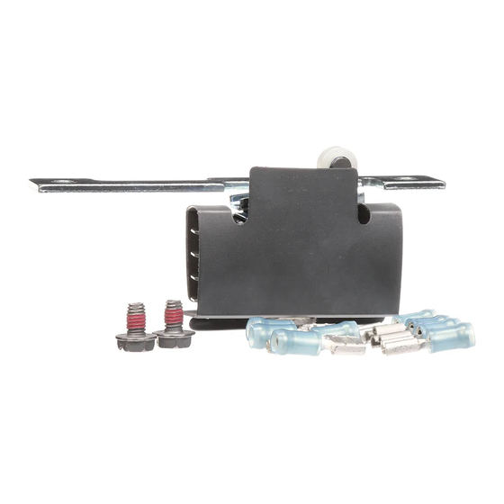
Auxiliary Contact Kit
Item:
1NO/1NC - Catalog Number HA161234,
2NO/2NC - Catalog Number HA261234,
Low Voltage - Catalog Number HA361234.
30 -600 Amp Fused VBII Heavy Duty
For use with:
Safety Switches
1
2
Page
of
500197A03
Pc. No.
5. Crimp on terminals supplied in kit to signal wires and
attach them securely to switch using Fig. 2 for proper
connections.
Note: All auxiliary switch conductors must be securely
routed away from any moving parts in the switch to pre-
vent malfunction of main and/or auxiliary switches.
6. Close and affix with interlocking tabs the auxiliary switch
electrical shield, Item A, Fig.1, around auxiliary switch
and wires to prevent accidental short to ground.
7. Close cover before supplying power to the Safety Switch.
Auxiliary Contacts
Switch
Aux. Switch
Ampere
Catalog
Rating
Number
With 1NO/1NC Isolated Contacts
30-600
HA161234
With 2NO/2NC Isolated Contacts
30-600
HA261234
Low Current PLC Type with 1NO/1NC Gold Plated Contacts
30-600
HA361234
A
1NO/1NC KITS HA161234 & HA361234
2NO/2NC KIT HA261234
Kit Ampere Rating
Kit Horsepower Rating
125V AC
250V AC
28V DC 125V AC
250V AC
Max.
Max.
Max.
Max.
10
10
1/2
10
10
7
1/2
10
10
1/2
Fig. 2
28V DC
Max.
Max.
3/4
3/4
3/4
Publicité

Sommaire des Matières pour Siemens 1 NO/1 NF
- Page 1 1NO/1NC - Catalog Number HA161234, 2NO/2NC - Catalog Number HA261234, Low Voltage - Catalog Number HA361234. 30 -600 Amp Fused VBII Heavy Duty For use with: Siemens Industry Inc. Safety Switches Norcross,Ga 30092 U.S.A. Page For questions call 1-800-241-4453 or our web site: http://www.usa.siemens.com/powerdistribution...
- Page 2 Jeu de contacts auxiliaires Article: 1 NO/1 NF : numéro de catalogue HA161234 2 NO/2 NF : numéro de catalogue HA261234 Basse tention : numéro de catalogue HA361234 Pour emploi avec: Interrupteurs de sécurité VBII d’usage industriel 30-600 A 2 (Francaise) Page Siemens Industry Inc.


