Table des Matières
Publicité
Les langues disponibles
Les langues disponibles
Liens rapides
Publicité
Chapitres
Table des Matières

Manuels Connexes pour DOLD SAFEMASTER UF 6925


Sommaire des Matières pour DOLD SAFEMASTER UF 6925
- Page 1 Datenblatt / Betriebsanleitung DEUTSCH SAFEMASTER Not-Aus-Modul UF 6925 Original E. DOLD & SÖHNE KG Postfach 1251 • 78114 Furtwangen • Deutschland Telefon +49 7723 6540 • Fax +49 7723 654356 0275136 dold-relays@dold.com • www.dold.com UF 6925 / 23.12.20 de / 352A...
-
Page 2: Table Des Matières
Inhaltsverzeichnis Symbol- und Hinweiserklärung ............................3 Allgemeine Hinweise ................................3 Bestimmungsgemäße Verwendung ...........................3 Sicherheitshinweise ................................3 Produktbeschreibung .................................5 Funktionsdiagramm ................................5 Schaltbilder ..................................5 Zulassungen und Kennzeichen ............................5 Anwendungen ..................................5 Geräteanzeigen .................................5 Anschlussklemmen ................................6 Blockschaltbilder ................................6 Hinweise ....................................6 Technische Daten ................................7 Technische Daten ................................7 UL-Daten ...................................7 Standardtype ..................................7 Varianten ...................................8 Vorgehen bei Störungen ..............................8... -
Page 3: Symbol- Und Hinweiserklärung
Anlage oder Maschine die korrekte Gesamtfunktion sicherzustellen. automatischen Start nach einem Not-Aus verhindern. DOLD ist nicht in der Lage, alle Eigenschaften einer Gesamtanlage oder • Durch Öffnen des Gehäuses oder eigenmächtige Umbauten erlischt Maschine, die nicht durch DOLD konzipiert wurde, zu garantieren. Das jegliche Gewährleistung. - Page 4 UF 6925 / 23.12.20 de / 352A...
-
Page 5: Produktbeschreibung
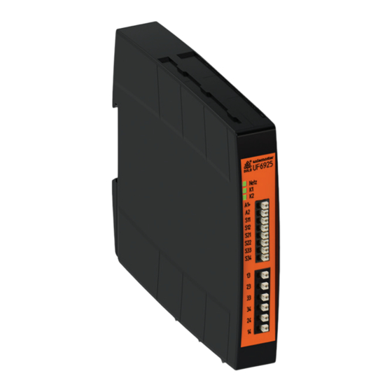
Sicherheitstechnik SAFEMASTER Not-Aus-Modul UF 6925 Ihre Vorteile • Für Sicherheitsanwendungen bis PL e / Kat. 4 bzw. SIL 3 • Geringer Platzbedarf • Frontseitiger Geräteanschluss • Manueller oder automatischer Start • Geeignet auch für Schutztüren • Leitungsschlusserkennung am Ein-Taster Merkmale •... -
Page 6: Anschlussklemmen
Anschlussklemmen Hinweise Einstellung Betriebsart Querschlusserkennung Klemmenbezeichnung Signalbeschreibung Die Wahl der Betriebsart mit oder ohne Querschlusserkennung am Not- Aus-Taster bzw. an der Schutztür erfolgt über den Schalter S1. Der Gerä- teanschluss ist gemäß Anwendungsbeispiel vorzunehmen. Die Einstellung S12, S22, S34 Steuereingänge an S1 muss vor Inbetriebnahme des Gerätes erfolgen. -
Page 7: Technische Daten
Technische Daten Technische Daten Gehäuse: IP 40 IEC/EN 60529 Eingang Klemmen: IP 20 IEC/EN 60529 Gehäuse: Nennspannung U DC 24 V, DC 8 ... 36 V Thermoplast mit V0-Verhalten Das Netzteil muss die Anforderungen nach UL Subject 94 von SELV / PELV erfüllen Rüttelfestigkeit: Amplitude 0,35 mm Spannungsbereich... -
Page 8: Varianten
Varianten Wartung und Instandsetzung UF 6925._ _ /1 _ _: - Das Gerät enthält keine Teile, die einer Wartung bedürfen. Schalten von Kleinlasten 10 mVA ... 12 VA bzw. 10 mW ... 12 W im Bereich - Bei vorliegenden Fehlern das Gerät nicht öffnen, sondern an den von 2 ... -
Page 9: Anwendungsbeispiel
Anwendungsbeispiel DC24V Sicherheitsfunktion UF6925 M10784_a Für automatische Ein-Funktion ist eine Brücke S33 - S34 zu setzen. Der Ein-Taster entfällt. Die gewünschte Start-Funktion muss über den Schalter S2 vor Inbetriebnahme des Gerätes eingestellt werden (siehe Hinweis "Geräteprogrammierung"). Die Funktion der externen Schütze wird durch Einschleifen der Öffnerkontakte in den Einschaltkreis (Klemmen S33 - S34) überwacht. Sicherheitsfunktionen für Geräte mit Querschlusserkennung (Bitte Hinweis "Geräteprogrammierung"... - Page 10 E. DOLD & SÖHNE KG • D-78114 Furtwangen • Postfach 1251 • Telefon 0 77 23 / 654-0 • Telefax 0 77 23 / 654-356 e-mail: dold-relays@dold.com • internet: http://www.dold.com UF 6925 / 23.12.20 de / 352A...
- Page 11 SAFEMASTER Emergency Stop Module UF 6925 Translation of the original instructions E. DOLD & SÖHNE KG P.O. Box 1251 • D-78114 Furtwangen • Germany Tel: +49 7723 6540 • Fax +49 7723 654356 0275136 dold-relays@dold.com • www.dold.com UF 6925 / 23.12.20 en / 352A...
- Page 12 Contents Symbol and Notes Statement ............................13 General Notes .................................13 Designated Use ................................13 Safety Notes ..................................13 Product Description .................................15 Function Diagram ................................15 Circuit Diagrams ................................15 Approvals and Markings ..............................15 Applications ..................................15 Indicators ..................................15 Connection Terminals ..............................16 Block Diagrams ................................16 Notes ....................................16 Technical Data .................................17 Technical Data .................................17 UL-Data ...................................17...
-
Page 13: Symbol And Notes Statement
DOLD cannot guarantee all the specifications of an installation or machine that was not designed by DOLD. The total concept of the control system into which the device is integrated must be validated by the user. DOLD also takes over no liability for recommendations which are given or implied in the following description. - Page 14 UF 6925 / 23.12.20 en / 352A...
-
Page 15: Product Description
Safety Technique SAFEMASTER Emergency Stop Module UF 6925 Your Advantages • For safety applications up to PL e / Cat. 4 e.g. SIL 3 • Space saving • Connection front side • Manual or automatic start • Can be used also for safety gate •... -
Page 16: Connection Terminals
Connection Terminals Notes Setting Cross fault detection Terminal designation Signal description Switch S1 is for selecting with or without cross fault detection at the e-stop button resp. on safety gate. For connection please see application examples. S12, S22, S34 Control inputs ATTENTION! The setting of S1 has to be made before S11, S21, S33 Control outputs... -
Page 17: Technical Data
Technical Data Technical Data Degree of protection: Input Housing: IP 40 IEC/EN 60529 Terminals: IP 20 IEC/EN 60529 Nominal Voltage U DC 24 V, DC 8 ... 36 V Housing: thermoplastic with V0 behaviour The power supply shall meet the according to UL subject 94 requirements of SELV / PELV Vibration resistance:... -
Page 18: Variants
Variants Maintenance and repairs UF 6925._ _ /1 _ _: - The device contains no parts that require maintenance. For switching small loads of 10 mVA ... 12 VA bzw. 10 mW ... 12 W in the - In case of failure, do not open the device but send it to manufacturer ranges 2 ... -
Page 19: Application Examples
Application Examples DC24V safety function UF6925 M11695 A jumper must be fitted S33 - S34 for the automatic On function. The On pushbutton is not required. The required start function has to be selected on switch S1 before starting the device. (see "Unit Programming"). Functioning of the external contactors is monitored by looping the NC contacts into the closing circuit (terminals S33 - S34). - Page 20 E. DOLD & SÖHNE KG • D-78114 Furtwangen • PO Box 1251 • Telephone (+49) 77 23 / 654-0 • Telefax (+49) 77 23 / 654-356 e-mail: dold-relays@dold.com • internet: http://www.dold.com UF 6925 / 23.12.20 en / 352A...
-
Page 21: Module D'arrêt D'urgence
SAFEMASTER Module d'arrêt d'urgence UF 6925 Traduction de la notice originale E. DOLD & SÖHNE KG B.P. 1251 • 78114 Furtwangen • Allemagne Tél. +49 7723 6540 • Fax +49 7723 654356 0275136 dold-relays@dold.com • www.dold.com UF 6925 / 23.12.20 fr / 352A... - Page 22 Tables des matières Explication des symboles et remarques ..........................23 Remarques ..................................23 Usage approprié ................................23 Consignes de sécurité ..............................23 Description du produit ..............................25 Diagramme de fonctionnement ............................25 Schémas ..................................25 Homologations et sigles ..............................25 Utilisations ..................................25 Affichages ..................................25 Borniers ...................................26 Schémas-bloc ..................................26 Remarques ..................................26 Caractéristiques techniques ............................27 Caractéristiques techniques ............................27...
-
Page 23: Explication Des Symboles Et Remarques
• L'ouverture de l'appareil ou des transformations non autorisées annulent chine. DOLD n'est pas en mesure de garantir toutes les caractéristiques la garantie. d'une installation ou d'une machine dont la conception lui échappe. C'est à... - Page 24 UF 6925 / 23.12.20 fr / 352A...
-
Page 25: Technique De Sécurité
Technique de sécurité SAFEMASTER Module d'arrêt d'urgence UF 6925 Vos avantages • Pour applications sécuritaires jusqu’à Pl e / Cat 4 resp. SIL 3 • Encombrement réduit • Raccordement de l'appareil frontal • Démarrage manuel ou automatique • Convient également pour des portes de protection •... -
Page 26: Borniers
Borniers Remarques Réglage de détection des courts-circuits transversaux Repérage des bornes Description du Signal La sélection du type de service (avec ou sans détection des courtscircuits transversaux sur le module d'arrêt d'urgence ou à la porte de protection) s'effectue au moyen de l'interrupteur S1. S12, S22, S34 Entrées de commande Le branchement de l´appareil doit être fait selon l´exemple d´utilisation.. -
Page 27: Caractéristiques Techniques
Caractéristiques techniques Caractéristiques techniques Degré de protection Entrée Boîtier: IP 40 IEC/EN 60529 Bornes: IP 20 IEC/EN 60529 Tension assignée U DC 24 V, DC 8 ... 36 V Boîtiers: thermoplastique à comportement V0 L‘alimentation devant répondre aux selon UL Subj. 94 exigences d‘une alimentation TBTS/TBTP Plage de tension Résistance aux vibrations:... -
Page 28: Variantes
Variantes Entretien et remise en état UF 6925._ _ /1 _ _: - Cet appareil ne contient pas de composants requérant un entretien. Couplage de faibles charges 10 mVA ... 12 VA ou 10 mW ... 12 W dans la - En cas de disfonctionnement, ne pas ouvrir l'appareil, mais le renvoyer plage de 2 ... -
Page 29: Exemples D'utilisation
Exemples d‘utilisation DC24V marche fonction de sécurité UF6925 M11696 Pour la fonction Marche automatique, il faut ponter S33 - S34. Le bouton Marche est supprimé. La fonction Start doit être règlée au B.P. S2 avant la mise sous service de l'appareil (voir remarques "Programmation de l‘appareil"). La fonction des contacteurs externes est contrôlée par l'insertion des contacts à... - Page 30 E. Dold & Söhne GmbH & Co. KG • D-78120 Furtwangen • Bregstraße 18 • Téléphone +49 7723 654-0 • Fax +49 7723 654356 dold-relays@dold.com • www.dold.com UF 6925 / 23.12.20 fr / 352A...
-
Page 31: Marquage Et Raccordements
Beschriftung und Anschlüsse Labeling and connections Marquage et raccordements M11697 DIN 5264-A; 0,5 x 3 A = 8 mm 1 x 0,2 ... 1,5 mm 1 x AWG 24 to 16 M10248 A = 8 mm 1 x 0,25 ... 0,75 mm 1 x AWG 24 to 16 M10249 A = 8 mm... -
Page 32: Dimensions (Dimensions En Mm)
Maßbild (Maße in mm) Dimensions (dimensions in mm) Dimensions (dimensions en mm) 122,6 17,5 115,3 Geräteprogrammierung Setting Programmation de l'appareil S1 Querschlusserkennung mit ohne S1 Transversal avec sans S2 Start Hand M11589_a Auto S2 Reset ... -
Page 33: Sicherheitstechnische Kenndaten
Sicherheitstechnische Kenndaten Safety Related Data Données techniques sécuritaires EN ISO 13849-1: Anforderung seitens der Sicherheits- Intervall für zyklische Überprüfung Kategorie / Category: funktion an das Gerät der Sicherheitsfunktion im High Demand Mode MTTF 284,6 a (year) Demand to our device based on the evaluated neccessary safety level of Intervall for cyclic test of the safety 99,0... -
Page 34: Eg-Konformitätserklärung
EG-Konformitätserklärung CE-Declaration of Conformity Déclaration de conformité européenne UF 6925 / 23.12.20 de / en / fr / 352A... -
Page 35: Note
Notizen Notice Note UF 6925 / 23.12.20 de / en / fr / 352A... - Page 36 E. DOLD & SÖHNE KG • D-78120 Furtwangen • Bregstraße 18 • Telefon 0 77 23 / 654-0 • Telefax 0 77 23 / 654-356 e-mail: dold-relays@dold.com • internet: http://www.dold.com UF 6925 / 23.12.20 de / en / fr / 352A...