Table des Matières
Publicité
Les langues disponibles
Les langues disponibles
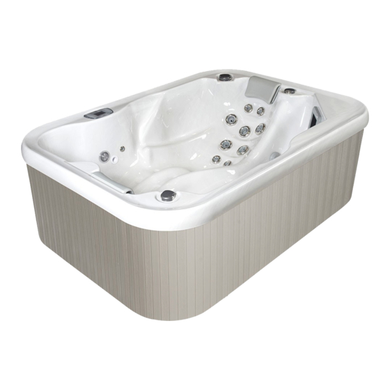
Spas ST 2.18 - ST 3.17 - ST 4.31
Portables et encastrables
ST 2.18 - 2 positions
NOTICE D'INSTALLATION ET CONSEILS D'UTILISATION
(à lire attentivement et à conserver pour utilisation ultérieure)
BIEN-ÊTRE
ST 3.17 - 3 positions
2021/02 - Indice de révision : E - Code : 37791
ST 4.31 - 4 positions
FR | PAGE 1 - EN | PAGE 33
1/64
Publicité
Chapitres
Table des Matières

Manuels Connexes pour BWT Spas ST 2.18

Sommaire des Matières pour BWT Spas ST 2.18
- Page 1 Spas ST 2.18 - ST 3.17 - ST 4.31 Portables et encastrables ST 2.18 - 2 positions ST 3.17 - 3 positions ST 4.31 - 4 positions NOTICE D’INSTALLATION ET CONSEILS D’UTILISATION (à lire attentivement et à conserver pour utilisation ultérieure)
-
Page 2: Table Des Matières
1. SYNTHÈSE DES INSTRUCTIONS DE SÉCURITÉ ........... 3 Norme NF C 15-100 .........................3 DDR (Dispositif Différentiel Résiduel)...................3 Risque d’électrocution ......................4 Risque de noyade ........................4 Risque de malaise........................4 Risque de chute ou de blessure ....................4 Risque d’intoxication......................4 Risque sanitaire ........................4 2. CARACTÉRISTIQUES TECHNIQUES ............. 5 3. -
Page 3: Synthèse Des Instructions De Sécurité
SYNTHÈSE DES INSTRUCTIONS DE SÉCURITÉ Norme NF C 15-100 En France, le spa doit être installé à un emplacement tel que les restrictions suivantes, relatives aux volumes de sécurité électrique de la norme C15-100, soient respectées. Volume 3 Hors Volume Volume 3 Volume 2 Volume 1 2.40 m 0.60 m Limites valables sur tout le pourtour Volume0... -
Page 4: Risque D'électrocution
Risque d’électrocution • L’escalier d’accès au spa qui recouvre la platine du spa doit toujours être fixé à l’habillage du spa avec les deux vis prévues à cet effet (voir paragraphe 4.6). Ces vis ne doivent être retirées que lors des interventions de SAV sur la platine, et après avoir déconnecté électriquement le spa. Elles doivent être reposées immédiatement en fin d’intervention. • Ne jamais utiliser manipuler d’appareil électrique branché lorsqu’on est dans le spa ou immédiatement en sortant du spa. De façon générale, ne jamais apporter d’appareil électrique dans le spa ou à proximité. Risque de noyade • Ne pas laisser de jeunes enfants utiliser le spa sans la surveillance d’un adulte responsable. • En présence de jeunes enfants dans l’habitation, toujours installer la couverture sur le spa et verrouiller les sangles de sécurité en dehors des périodes d’utilisation. Risque de malaise • Les personnes affectées de problèmes de santé, les femmes enceintes, ainsi que les personnes âgées devront consulter leur médecin pour savoir si leur état leur permet l’utilisation d’un spa et dans quelles limites. • Prendre également des précautions particulières concernant les enfants en bas âge : le corps des très jeunes enfants notamment (moins de 2 ans) ne régule pas sa température efficacement. • Tester la température de l’eau avant d’entrer dans le spa : ne pas entrer brusquement dans un spa, notamment si son eau est chauffée à une température supérieure à 37°C, ou si la température de l’eau est inférieure à 28°C. • Nous vous recommandons de ne pas utiliser un spa plus d’une demi-heure d’affilé, et d’espacer un minimum les séances, une exposition prolongée du corps à... -
Page 5: Caractéristiques Techniques
CARACTÉRISTIQUES TECHNIQUES ST 2.18 ST 3.17 ST 4.31 version portable (sans escalier) Poids à vide (kg) Version encastrable Volume d’eau (litres) 1000 Nombre de positions version portable 1240 1620 Poids indicatif en eau et avec le nombre max d’utilisateurs (kg) Version encastrable 1200 1580 198 x 141 213 x 168 200 x 200 Dimensions hors tout (sans l’escalier) longueur x largeur x hauteur (cm) x 66 x 80... -
Page 6: Installation Et Mise En Service
INSTALLATION ET MISE EN SERVICE Ressources nécessaires Prévoir 4 personnes pour la manutention du spa. Outillage nécessaire : • Tournevis cruciformes : − PH1 attaches de couverture, adaptateur de tuyau de vidange, dépose du panneau du coffret de commande et connexion phase et neutre du câble d’alimentation électrique, − PZ2 vis de fixation de l’escalier. • Tournevis plat pour la terre du câble d’alimentation Choix de l’emplacement du spa Si le spa est installé... -
Page 7: Spas Encastrables
Les règles concernant les volumes de sécurité électrique devront être respectées (voir la synthèse de sécurité en début de notice). 3.2.2 Spas encastrables Nous conseillons de prévoir un espace d’environ 80 cm de large entre le spa et chacune des parois de la réservation. ATTENTION Le spa ne doit pas prendre appui en surface via le retour de cuve, mais reposer sur le fond de la réservation via son armature bois périphérique et en croix sous la cuve. - Page 8 ATTENTION Il est indispensable que de l’eau ne puisse pas stagner dans le fond de la réservation. Prévoir en fond de réservation une évacuation d’eau suffisante, voir un drainage périphérique si une nappe phréatique est située dans le sous-sol sous le spa. Une immersion prolongée du dessous de la cuve peut entraîner de graves dégradations. Si le spa est en extérieur à l’air libre, la plage et les parois de la réservation devront être suffisamment étanches pour limiter le ruissellement des eaux de pluie dans la réservation. La trappe d’accès devra être scellée de façon amovible ou plaquer sur un joint afin que l’eau de pluie ne puisse ruisseler dans la réservation. Si la réservation a été réalisée par décaissement du sol naturel, elle devra comporter une ventilation suffisante afin de limiter le taux d’humidité et le développement de moisissures. Par exemple, prévoir sur la plage de...
-
Page 9: Préparation Et Connexions Hydrauliques Et Électriques
Préparation et connexions hydrauliques et électriques 3.3.1 Connexions des platines intégrées Par mesure de sécurité, commencer par les connexions hydrauliques. A) Connexions hydrauliques Ouvrir le sachet de joints livré avec la platine. Celui-ci contient un adaptateur de rallonge pour le tuyau de vidange gravitaire (voir paragraphe 3.6), et les joints suivants : ST 2.18 et ST 3.17 ST 4.31 Pompe 2 joints toriques : diamètre intérieur Di = 58 mm et diamètre de corde Dc = 4,5 mm bi-vitesse et 1 pour le raccordement de l’aspiration de la pompe à la contre-platine réchauffeur 1 pour le raccordement de la sortie du coffret à la contre-platine 2 joints toriques : diamètre intérieur Di = 63... - Page 10 Le circuit amenant l’ozone gazeux depuis l’ozonateur jusqu’au venturi se présente quant à lui sous la forme d’un tube PVC blanc souple de 7 mm de diamètre décrivant une boucle située sous la cuve du spa au-dessus du niveau d’eau, afin d’éviter que l’eau ne puisse descendre jusqu’à l’ozonateur. Les deux extrémités de cette boucle sortent de la contre-platine et sont à...
- Page 11 Raccordement de la platine au secteur : Le câble (non fourni) à utiliser pour le raccordement du SPA au secteur doit être exclusivement de type HO7RN-F. Introduire le câble d’alimentation 230 volts + terre par le trou situé sur la gauche du coffret électrique. Ce câble devra être de section suffisante en rapport avec l’équipement complet du spa (voir tableau page suivante), et protégé en amont par un disjoncteur différentiel de 30 mA (norme électrique C15-100). Connecter le câble d’alimentation : la terre sur le bornier en aluminium situé à l’extérieur du coffret, le neutre sur la borne N et la phase sur la borne L1 (sous N) du bornier gris clair situé dans le coffret. Connecteur prévu Produits à brancher dans le coffret Main Panel (J35) Panneau de contrôle Spa Light (J15) Projecteur ou chromathérapie...
-
Page 12: Préparation Et Connexion De La Platine Déportée (Option)
Les seuils d’intensité de coupure pour la protection contre les surintensités figurent dans le tableau suivant : Section du câble d’alimentation cuivre pour une chute de tension inférieure à 5,0 % ST 2.18 et 3.17 ST 4.31 Modèle de spa Sans blower Avec blower Sans blower Avec blower Intensité (A) max absorbée 5 mètres 2,5 mm² 2,5 mm² 2,5 mm² 2,5 mm² Longueur 10 mètres 2,5 mm² 2,5 mm² 2,5 mm² 4 mm²... -
Page 13: Connexions Hydrauliques
B) Connexions hydrauliques : En cas de longueur importante, il faudra veiller à ce que les déperditions thermiques ne soient pas excessives le long des tuyauteries, et adopter les dispositions nécessaires (mise en terre, calfeutrage…). Composition des kits de déport des spas PORTABLES et ENCASTRABLES ST 2.18 et ST 3.17 ST 4.31 • 2 tuyaux eau Spirabel 7,50 m / Ø 50 Mêmes accessoires que pour le ST 2.18 et 3.17 • 1 vanne en Ø 25 (ozonateur), à séparer en deux Avec en plus, pour la pompe de massage : •... - Page 14 Pompes et coffret : • Couper chaque tuyau à la bonne longueur • Enfiler un collier Torro 40/60 à l’extrémité de chaque tuyau en diamètre 50 • Tremper quelques minutes l’extrémité des tuyaux en diamètre 50 dans de l’eau à 40°C, puis dans la foulée emmancher les raccords sur les tuyaux par leur extrémité cannelée, selon les schémas d’association ci- dessous • Serrer au tournevis plat les colliers Torro sur l’extrémité cannelée des raccords • Visser les écrous des raccords sur les raccords filetés correspondants (pompes, coffret, contre-platine), voir schémas ci-dessous : Raccordement de la pompe bi-vitesse : A - Raccord droit B- Raccord droit côté platine noir côté contre-platine noir...
- Page 15 Ozonateur : • Séparer une demi-union de la vanne en Ø 25 fournie dans le kit de déport en dévissant son écrou, et visser cette vanne côté platine à l’extrémité du tuyau venant du venturi d’ozone (écrou) • Couper 2x25 cm de tuyau en Ø intérieur 19, coller une de ses extrémité dans la ½ union de la vanne en Ø 25 précédemment posé côté platine, et dans l’autre extrémité coller une des réductions 26/35 • Prolonger la réduction par du tuyau en Ø 35 coupé à la bonne longueur • Coller à l’autre extrémité du tuyau Ø 35 la deuxième réduction 26/35 • Prolonger cette réduction par 25 cm de tuyau en intérieur de Ø 19 mm • Coller à son extrémité la demi-union qui avait été séparée de la vanne en Ø 25 • Visser dans cette demi-union la vanne en Ø 25 qui dépasse de la contre-platine Vanne de contre-platine Vanne Ø 25 Tuyau Ø 19 Tuyau Ø 35 Tuyau Ø 19 Vers Venturi Réduction Réduction 1/2 union de la Ozonateur 26/35 26/35 vanne Ø 25 Récupérer la boucle de l’ozonateur positionnée sous la cuve du spa en coupant le collier Rilsan. Ensuite, il convient d’installer, côté platine, la boucle de protection contre les remontées d’eau vers l’ozonateur (petit tube en PVC souple) : une extrémité de cette boucle doit être fixée sur le venturi, l’autre extrémité sur la sortie latérale basse (de façon indifférenciée).
-
Page 16: Alimentation Triphasé
C) Connexions électriques Il convient de faire cheminer ces câbles entre la platine et la contre-platine dans une gaine de protection, et de ne pas les tendre afin d’éviter d’endommager leurs connecteurs. Des dispositions identiques à celles des platines non déportées s’appliquent pour le raccordement de la platine au secteur. Alimentation triphasé Conversion du coffret électrique du spa en triphasé En cas d’alimention en triphasé, il est nécessaire avant d’alimenter la platine de modifier la connectique. 3.4.1 Modification de la connectique au niveau de la carte Coffret BP 6013 ou Coffret BP2100 Retirer le fil qui fait le pont entre J51 et J58. Retirer le fil qui fait le pont entre J52 et J36. Défaire au niveau de J53, le pont venant de J41 pour le repositionner en J54. -
Page 17: Remplissage Du Spa
Faire cheminer le câble à l’extérieur du spa comme prévu jusqu’à son point de raccordement, mais ne pas le connecter immédiatement. Si vous enterrez le câble ou si vous le faites passer dans une dalle, il est indispensable que celui-ci chemine dans une gaine afin de pouvoir être retiré le cas échéant. Nous vous recommandons de protéger spécifiquement la ligne d’alimentation du spa contre les sur- intensités et les court-circuits par un disjoncteur magnéto-thermique situé en tête du câble d’alimentation du spa. Celui-ci pourra également jouer le rôle de sectionneur en cas d’intervention sur les parties électriques. Remplissage du spa Avant le premier remplissage, s’assurer que les vannes déviatrices sont bien serrées pour une parfaite étanchéité. Les vibrations liées au transport peuvent entraîner un léger dévissage. Qualité... -
Page 18: Vidange Du Spa
Ne pas trop remplir le spa, celui-ci pourrait déborder lorsque les utilisateurs y entrent et endommager l’ozonateur de façon irréversible. Vérifier régulièrement le niveau de l’eau et l’ajuster si nécessaire. Pendant les périodes de non-utilisation du spa, il est recommandé de le conserver fermé par sa couverture, afin d’éviter l’évaporation, les pertes calorifiques et la pollution. ST 4.31 : VOTRE SPA EST ÉQUIPÉ DE PIEDS POUR SOUTENIR LA CUVE LORSQU’IL EST EN EAU. Pour le réglage des pieds (ST 4.31) : Votre spa est équipé... -
Page 19: Amorçage Des Pompes
centimètres d’eau resteront dans le fond de la cuve en fin de vidange. De façon analogue, il est possible qu’il reste un peu d’eau dans certaines tuyauteries du circuit hydraulique. Par conséquent, si le spa est vidé et reste ainsi sans eau et à l’arrêt pendant une longue période, nous vous recommandons, d’une part de dévisser les raccords de pompes pour compléter la vidange, et d’autre part de procéder à une chloration choc de l’eau lors de son re-remplissage (voir paragraphe 6 – traitement de l’eau). Amorçage des pompes Suivant le modèle, la platine peut avoir une ou deux pompes. Procéder à l’amorçage des pompes avant d’utiliser le spa : Désalimenter électriquement le spa Il est conseillé de retirer les cartouches filtrantes du skimmer afin de faciliter l’amorçage de la pompe bi-vitesse (voir paragraphe 5.1) Pour chacune des pompes : − desserrer l’écrou du raccord union situé sur l’aspiration de la pompe (tuyau horizontal) afin de faire sortir l’air jusqu’à ce que de l’eau s’en écoule ; − resserrer le raccord Réalimenter électriquement le spa Mettre les pompes en fonctionnement avec le bouton JETS du panneau de contrôle. Celles-ci doivent s’amorçer et de l’air s’échappe un instant par les buses de massage. Voir la notice du panneau de... -
Page 20: Fixation De L'escalier Sur Le Spa (Spas Portables Uniquement)
Fixation de l’escalier sur le spa (spas portables UNIQUEMENT) L’escalier se fixe au spa par ses côtés, au niveau de deux pattes en bois qui dépassent de la contre- platine. ATTENTION Pour cette opération, l’escalier doit être plaque contre le spa avant le vissage. Présenter l’escalier face à la contre-platine de sorte que les deux cales en bois se positionnent sous l’escalier. Pousser l’escalier contre l’habillage du spa, et le maintenir plaqué pendant le vissage au travers des 2 avant-trous, en utilisant 2 vis VB FZ ST 5x60 inox A2 fournies. - Page 21 Ci-après, les différents secteurs et leurs vannes déviatrices ainsi que les contrôleurs d’air qui leurs correspondent : ST 2.18 ST 3.17 21/64 BIEN-ÊTRE 2021/02 - Indice de révision : E - Code : 37791...
- Page 22 ST 4.31 Contrôleur d’air (pour mélanger de l’air à l’eau en proportion variable) Compartiment Aromathérapie (comprimé qui parfume l’air injecté par le blower) Vanne déviatrice, dirige le flux de la pompe vers un secteur ou un autre Panneau de contrôle Cascade anne de la cascade 22/64 2021/02 - Indice de révision : E - Code : 37791 BIEN-ÊTRE...
-
Page 23: Option « Chromathérapie
Désignation Description Permet de diriger le flux d’une pompe vers Vanne déviatrice un secteur ou un autre. Contrôle le débit des bulles d’air envoyées Contrôleur d’air dans les buses de massage. Jets de massage fixes orientables en Jets orientables direction. Le débit de chaque buse se règle (70mm, 95mm) par rotation de sa couronne extérieure. Jet de massage rotatif. Le débit de chaque Jets rotatifs buse se règle par rotation de sa couronne (70mm, 95mm) extérieure. Jet de massage rotatif. Le débit de chaque Jet bi-rotatif (95mm) buse se règle par rotation de sa couronne... -
Page 24: Ozonateur
les 2 semaines pour une installation intérieure. Par la suite, suivant le degré de colmatage des cartouches, l’utilisateur prendra l’habitude et trouvera de lui-même les cadences les mieux adaptées. Une baisse de débit des buses de massage des secteurs de la pompe 1 est un signe caractéristique de colmatage des cartouches filtrantes et donc d’un besoin de nettoyage. Dépose / repose des cartouches filtrantes : • Arrêter la pompe 1 (filtration / massage) si celle-ci est en fonctionnement. • Tirer vers le haut le cadre extérieur du skimmer supportant le volet flottant pour le débloquer, puis le retirer. • Retirer le panier en le coulissant horizontalement vers l’intérieur du spa. La (les) cartouches sont maintenant visibles. • Dévisser et retirer la (les) cartouches. -
Page 25: Buses Rotatives
Buses rotatives Les buses rotatives sont équipées de roulements à billes en matière plastique susceptibles de s’encrasser dans le temps et de provoquer la non-rotation du jet. Pour procéder à leur nettoyage : • Insérer l’extrémité d’un tournevis plat derrière la languette de la buse, dans l’encoche en périphérie de la partie tournante. • Pousser et maintenir la languette vers le centre, et tirer simultanément le jet rotatif vers l’extérieur pour le sortir du corps de buse • Nettoyer à l’air comprimé injecté dans le conduit arrière de la buse jusqu’à obtenir la rotation libre. • Remettre le jet en place : enfoncer et tourner en poussant légèrement jusqu’à l’obtention d’un “clic” de bocage. Dans le cas d’une eau dure (TH>20°) et si l’eau n’est pas traitée, un dépôt de calcaire pourra se former sur le corps de buse et son roulement, empêchant la rotation de la buse ou rendant difficile le réglage de débit de sa face avant. Cuve acrylique Pour conserver le bel aspect de cette surface, respecter les conseils suivants pour le nettoyage de la cuve : •... -
Page 26: Habillage Composite
permet de protéger la cuve acrylique contre les variations de la température entre la partie immergée et la partie au-dessus du niveau d’eau. Il est normal, suite au procédé de fabrication par thermoformage de la cuve, de pouvoir observer les particularités suivantes : • une variation de la hauteur du rebord du spa de ± 6 mm. • de légères ondulations sur la partie supérieure, dues au retrait de la matière du renfort. Habillage composite De série, la version portable de nos spas bénéficie d’un habillage en composite, qui ne nécessite aucun entretien particulier. L’épaisseur du lambris composite est de 7 mm. Au besoin, nettoyer avec de l’eau savonneuse. Ne jamais utiliser de produits abrasifs ou de solvants. -
Page 27: Traitement De L'eau
TRAITEMENT DE L’EAU pH de l’eau Il est important, de maintenir le pH de l’eau entre 7.0 et 7.6 afin d’obtenir une bonne désinfection de l’eau et d’éviter une agression de la peau des utilisateurs. Procéder régulièrement à une analyse du pH et utiliser AQUAPLUS granulés et AQUAMINUS granulés pour relever ou abaisser le pH de l’eau. Se référer au tableau ci-dessous pour les quantités de produit à utiliser selon le volume des spas. Ex : Valeur mesurée 7.5, pour abaisser le pH à 7.0 il faudra gr. d’AQUAMINUS dans le cas du spa ST 4.31 ST 4.31 (1000 l) ST 3.17 (750 l) ST 2.18(490 l) Valeur de pH de départ Quantité de produit à ajouter en grammes Aquaminus... - Page 28 L’ozonateur fonctionne automatiquement pendant les périodes de filtration du spa. Le maintien d’un pH correct ainsi que d’un taux suffisant de désinfectant est essentiel. L’ozone participe au traitement chimique, mais ne le remplace pas. L’ozonateur a un potentiel de production de 3 à 4 années. Passé ce délai, il faudra procéder à son remplacement. Oxygène actif (monopersulfate de potassium - OXYSPA) ATTENTION Ne pas confondre avec le péroxyde d’hydrogène qui est aussi un produit oxygéné, mais qui peut entraîner de graves dégradations du spa. L’oxygène actif est le stérilisant le mieux adapté au spa du fait de sa puissance anti microbienne et de son absence totale d’odeur. Dose : une pastille 20 gr par 1000 litres d’eau. Suivant l’utilisation, ajouter une pastille une à deux fois par semaine dans le panier du skimmer, filtration en fonctionnement, 30 minutes avant le bain. Chloration choc Il est recommandé d’effectuer une fois pas mois une chloration choc du spa afin d’éliminer tout résidu microbien qui pourrait s’adapter au traitement courant et se nicher dans les parties inaccessibles (circuits d’eau et d’air).
-
Page 29: Couverture Isothermique
COUVERTURE ISOTHERMIQUE Il est recommandé de toujours conserver la couverture isothermique en place lorsque le spa n’est pas utilisé. La couverture a plusieurs fonctions : • conservation des calories et économie d’énergie • conservation des produits de traitement • prévention de la pollution • sécurité pour les enfants en bas âge • protection de la cuve acrylique Les couvertures sont traitées anti-U.V. Pour le nettoyage, utiliser de l’eau, seule ou savonneuse. Ne pas utiliser d’autres produits. La couverture est livrée équipée de 4 sangles, chacune comportant des attaches à serrure pour sécuriser l’accès au spa. -
Page 30: Garantie Limitée
GARANTIE LIMITÉE Les spas BWT sont couverts par une garantie limitée. Celle-ci protège uniquement l’acheteur initial du spa. Couvertures de garantie : 5 ans contre tout défaut de coque et de surface de coque – La coque du spa est garantie contre les fuites d’eau survenant à la suite d’un défaut dans sa structure, et cela pour une durée de 5 (cinq) ans suivant la date initiale d’achat du spa. 2 ans contre toute défectuosité des composants et de la plomberie – Les composants de la platine de filtration ainsi que les composants de la plomberie installés lors de la fabrication, sont garantis pour une durée de 2 ans suivant la date initiale d’achat du spa. Le déport de la platine Procopi BWT Group à plus de 7,50 m du spa, ainsi que l’utilisation pour le déport de câbles ou rallonges autres que ceux livrés avec le spa annulent la garantie. Couverture isothermique La couverture est garantie 2 ans suivant la date initiale d’achat du spa. Les déformations liées à une surcharge sur la couverture ne sont pas garanties. - Page 31 31/64 BIEN-ÊTRE 2021/02 - Indice de révision : E - Code : 37791...
- Page 32 32/64 2021/02 - Indice de révision : E - Code : 37791 BIEN-ÊTRE...
- Page 33 ST 2.18 - ST 3.17 - ST 4.31 SPAS Portable and in-ground versions ST 2.18 - 2 massage stations ST 3.17 - 3 massage stations ST 4.31 - 4 massage stations INSTALLATION AND OPERATING INSTRUCTIONS (to be read carefully and kept for future reference) FR | PAGE 1 - EN | PAGE 33 33/64 BIEN-ÊTRE 2021/02 - Indice de révision : E - Code : 37791...
- Page 34 1. SAFETY INSTRUCTIONS ................35 The NF C-15 standard ......................35 RCD (Residual Current Device) ...................35 Risk of electrocution ......................36 Risk of drowning ........................36 Risk of falling ill ........................36 Risk of falling or injury ......................36 Risk of poisoning ........................36 Health risks..........................36 2.
-
Page 35: Safety Instructions
SAFETY INSTRUCTIONS The NF C-15 standard Within France, the spa installation site must be selected in accordance with the restrictions set out in the French safety standard, C15-100. Volume 3 no restrictions apply Volume 3 Volume 2 Volume 1 2.40 m 0.60 m Spacing applicable around the entire Volume0 periphery of the spa Volume 0: no electrical equipment other than that integrated into the spa Volume 1: only plugs, switches, electrical equipment and lights running off Safety Extra Low Voltage (voltage limited to 12V AC or 30 V DC) are permitted, the power source being located outside volumes 0, 1 and 2. -
Page 36: Risk Of Electrocution
Risk of electrocution • The spa steps that house the spa pack must always be fastened to the spa with the two screws provided for this purpose (see paragraph 3.8). These screws should only be removed to allow servicing of the spa pack, and then only after the power supply to the spa pack has been cut. They should be replaced immediately after the intervention. • Never use or handle an electrical appliance that is plugged in while in the spa or on exiting the spa. More generally, never bring an electrical appliance into or near the spa. Risk of drowning • Never allow young children to use the spa without supervision by a responsible adult. • If there are young children in the home, always cover the spa and lock the safety straps while the spa is not in use. Risk of falling ill • People with health problems, pregnant women and older people should consult their doctor to make sure that it is safe for them to use the spa and check if any limitations apply. • Take special precautions with very young children. Very young children (younger than 2 years old) have difficulty regulating their body temperature. • Test the water temperature before entering the spa: never enter the spa quickly, particularly if the water temperature is above 37°C or below 28°C. • We recommend that spa sessions be limited to 30 minutes, and that you space out sessions, prolonged exposure of the body to high temperatures can cause elevation of the body temperature. • If you feel dizzy, nauseous or particularly tired, leave the spa immediately. Risk of falling or injury •... -
Page 37: Technical Data
TECHNICAL DATA ST 2.18 ST 3.17 ST 4.31 Portable spa (without steps) Empty weight (kg) In-ground spa Water volume (litres) 1000 Number of massage stations Indicative weight filled with Portable version 1240 1620 water and the maximum number of users In-ground version 1200 1580 198 x 141 x 213 x 168 x 200 x 200 x Overall dimensions (without steps) length x width x height (cm) Overall step dimensions (portable spas only) 106 x 42 x 55 122 x 55 x 42 122 x 55 x 42 (length x width x height in cm) Power supply - phase/voltage... -
Page 38: Installation And Commisioning
INSTALLATION AND COMMISIONING Tools required 4 people will be needed to carry the spa. Tools required: • Phillips head screw drivers: − PH1 cover fasteners, drain line adapter, removing the control panel casing, and connecting the live and neutral wires of the power cable. − PZ2 Step fastening screws. • Flat head screw driver for the earth wire of the power cable. Siting Outdoor installation: • Do not install the spa near deciduous bushes or deciduous trees. • Check that rain water will not accumulate under or around the spa. Prolonged immersion of the surface underneath the spa can lead to damage Indoor installation: • We recommend that you ensure that the spa may be easily removed from the installation site if required (do not wall the spa in). • Make sure that the humidity that the spa will generate in the room will not damage decorative elements or any structures in the room (wooden floors, wood, materials, paintings, etc.). -
Page 39: In-Ground Spas
Regulations concerning electrical safety volumes must be respected (see the safety notice at the beginning of this document). 3.2.2 In-ground spas Leave a gap of at least 80 cm around the entire periphery of the spa to facilitate access to the spa components. IMPORTANT The spa should not hang from the lip of the spa shell, it should rest on its timber frame on the floor of the excavation. The floor of the excavation should be stable and perfectly flat (check using a spirit level) and able to bear the total weight of the spa (plus water, plus occupants) with deforming over time. If necessary, wedges may be inserted under support structure and spa to ensure that it is perfectly level and that water level is constant at every point. Excavation dimensions Ext dimensions of the timber support structure Model Height under the lip H Length L Width W ST 2.18 1935 mm... - Page 40 IMPORTANT Water must not be allowed to stagnate at the bottom of the excavation. Make sure that there is sufficient drainage at the bottom of the excavation, create a peripheral drain if the water table is close to the bottom of the spa. Prolonged submersion of the bottom of the spa will lead to serious damage. If the spa is placed outdoors in the open air, the decking and walls of the enclosure in which it is installed must be sealed to limit streaming of rain water into the enclosure. The access hatch must be sealed in a manner that allows it to be released, or set into a gasket to prevent rain water from streaming into the enclosure. If the enclosure was created by digging out soil, create adequate ventilation to keep the humidity level down and limit growth of mould. For example, install ventilation spurs (with a rain water anti- intrusion system) on either side of the spa. Water can be channelled away from the spa by forming a wedge shape for the spa to rest on and installing a peripheral drain (see digram below). Decking may be laid on reinforced concrete beams placed horizontally to rest on the peripheral walls and strategically located pillars. Slats may be placed between the beams to support the decking. The position of the pillars should not obstruct access to the area around the shell, notably if only one access hatch was created.
-
Page 41: Preparation, Hydraulic Connections And Wiring
Preparation, hydraulic connections and wiring 3.3.1 Spa pack connections As a safety precaution, start with the hydraulic connections. A) Hydraulic connections Open the bag of seals delivered with the spa pack. This contains a gravity drainage hose extension adaptor (see paragraph 3.6) and the following o-rings : ST 2.18 and ST 3.17 ST 4.31 Two speed 2 o-rings: inner diam 58 mm, string gauge Dc 4.5 mm pump and 1 for the spa pack mouting plate pump suction connection heater... - Page 42 from flowing back into the ozonator. Both ends of this loop protrude from the spa pack mounting plate, connect either end to the venturi tee and the other end to the ozonator. A check valve provides further protection to the ozonator. Connecting the blower (if this option is installed): Pull on the air hose protruding from the spa pack mounting plate (flexible tube, diameter 32 mm, equipped with a collar and barrel union), position the 49 mm diameter o-ring on the end of blower ‘s threaded outlet and screw the barrel union onto it. B) Wiring: For safety reasons, start by connecting the spa pack to the spa. Connecting the spa pack to the spa: Make sure that the power supply to the spa has been cut, then remove the casing of the electrical panel. Connect the control panel and the underwater light. IMPORTANT Do not alter the position of the 10 microswitches. They control spa configuration and any alteration could cause a malfunction.
- Page 43 Connecting the spa pack to the mains: The spa power cable (not supplied) must be HO7RN-F type. Pull the 230 V + earth cable into the electrical panel through the cable gland located on the left hand side of the electrical panel. The cross section of this cable should be sized for all the spa equipment (refer to the table on the next page), and protected upstream by a 30 mA RCD (French electrical safety standard C15-100). Connect the power cable: the earth to the aluminium terminal strip located on the outside of the panel, neutral to the N terminal and live to the L1 terminal (under N) of the light grey terminal block located in the panel. Connector Item to be connected in the panel Main Panel (J35) Control pad Spa Light (J15) UV light or chromatherapy Connector allocated Item already connected in the electrical panel Pump 1 (J9) Two-speed pump Circulation pump (J21) Not used...
-
Page 44: Preparation And Connection Of The Remote Installed Spa Pack (Option)
The trip values for protection against over currents are shown below. Cross section of the copper power cable for a voltage drop less than 5.0% SP 2.18 and 3.17 SP 4.31 Spa model No blower With blower No blower With blower Current (A) absorbed 15 A 15 A 22 A 26 A 2.5 mm² 2.5 mm² 2.5 mm² 2.5 mm² 10 m 2.5 mm² 2.5 mm²... -
Page 45: Hydraulic Connections
B) Hydraulic connections If the spa pack is installed at a significant distance from the spa, take any necessary measures to limit heat loss from the pipes (run underground, lagging, etc.). Remote installation kit composition for portable and in-ground spas ST 2.18 and ST 3.17 ST 4.31 • 2 Spirabel water hoses 7.50 m / Ø 50 Same accessories as for ST2.18 and ST 3.17 with the following additional items for the massage pump: • 1 valve Ø 25 (ozonator), to be separated in two • 2 Spirabel water hoses 7.50 m / Ø 50 • 0.5m of tubing Ø 19/26 • 4 SS TORRO 40/60 clamps • 8m of transparent, flexible tubing Ø 35, • 2 o-rings WHITE solvent (ozonator) •... - Page 46 Pumps and panel: • Cut each tube to the correct length • Slide a Torro 40/60 clamp onto the end of each 50 mm diameter tube • Soak the ends of the 50 mm diameter tube in water heated to 40 °C and then push the hose tails into the tubes as illustrated below. • Using a flat head screw driver, tighten the Torro clamps over the hose tails. • Screw the barrel union nuts onto the corresponding threaded unions (pumps, panel, spa pack mounting plate) as illustrated below. Connection of the two-speed pump: A- Straight union B- Straight union Spa pack side, Mounting plate black side, black Pipe diameter, 50 mm F- Elbow union Connection of the massage pump: Mounting plate side, white C- Elbow union Spa pack side, white...
- Page 47 Ozonator: • Undo barrel- union of the 25 mm valve supplied in the remote install kit. Mount the valve on the end of the ozone venturi tube on the spa pack side (nut). • Cut a 2 x 25 cm length of the 19 mm inner diam. tube, glue one end into the 25 mm valve previously mounted on the spa pack, and insert one of the 26/35 reduction fittings into the other end. • Extend the reduction fitting using a correctly sized length of the 35 mm diameter tubing. • Glue the other 26/35 reduction fitting into the other end of the 35 mm tube. • Extend this reduction with a 25 cm length of the 19 mm inner diameter tube. • Glue the half-union that was removed from the 25 mm valve to the end of the 26 mm diameter tube. • Screw this half-union onto the 25 mm valve protruding from the spa pack mounting plate. Mounting plate valve 25 mm valve 25 mm pipe 25 mm pipe 25 mm pipe Reduction fitting to venturi Reduction fitting 25 mm valve half 26/35 ozonator 26/35 union Retrieve the ozonator loop from under the spa shell by cutting the Rilsan clamp. Next, on the spa pack side, install the loop that will protect the ozonator against the back flow of water (thin, flexible PVC tubing). Mount either of the two ends of the loop on the venturi, the other on the bottom outlet. In order for the loop to fulfil its protective function, it must be fixed in position at a height above the bottom of the spa shell. Blower: On the spa pack mounting plate side; loosen the screw at the end of the protruding 32 mm tube to relese the blower reduction fitting. Undo the Torro clamp. Using a hair dryer, heat the tube to remove the hose tail union. •...
-
Page 48: Three Phase Power Supply
C) Wiring Run the cables between the spa pack and the spa pack mounting plate in a protective sheath. Do not stress load the cables, this could damage their connectors. Remote installed spa pack’s are wired in identically to spa packs that are installed against the spa. Three phase power supply Conversion of the spa electrical panel for a 3-phase power supply. To power the spa off a 3-phase supply, the connections in the electrical panel will need to be modified. 3.4.1 Modifying connections on the PCB Spa packs BP6013 and BP2100 Remove the jumper between J51 and J58. Remove the jumper between J52 and J36. Disconnect the jumper coming from J41 at J53 and reconnect it to J54. Disconnect the jumper coming from J60 at J12 and reconnect it to J45. 3.4.2 Micro-switch configuration Spa packs BP6013 and BP2100 The electrical panel is configured for single phase operation in the factory. All the micro-switches are... -
Page 49: Filling The Spa
We recommend that a thermal magnetic circuit breaker be installed at the head of the line to protect against over-voltages and short circuits. This can also act as a breaker to allow interventions on the electrical components. Filling the spa Before filling the spa make sure that all the diverting valves are closed to ensure that there will be no leaks. -
Page 50: Draining The Spa
ST 4.31 : YOUR SPA IS FITTED WITH PEDESTALS TO PROVIDE SUPPORT TO THE SPA SHELL WHEN IT IS FILLED WITH WATER. To adjust the height of the pedestals: Votre spa est équipé de pieds pour soutenir la • fill the spa with water, cuve lorsqu’il est en eau •... -
Page 51: Priming The Pumps
Nota bene: The main drains through which water flows from the spa to the drain valve are located on a vertical wall just above the lowest point of the spa shell. This means that, after draining, a few centimetres of water will remain in the bottom of the spa. Similarly, some water may remain in the pipework. Consequently, if the spa is to be left empty for a long period of time, we recommend that you undo the pump unions to completely drain the spa, and that you carry out a Chlorine shock treatment upon refilling the spa (see paragraph 6 - water treatment). Priming the pumps The spa pack is equipped with one or two pumps depending on the model. Prime the pumps before using the spa: Cut the power supply to the spa We recommend that you remove the filter cartridge from the skimmer to facilitate priming of the two- speed pump (see paragraph 5.1). For each of the pumps do the following, − Loosen the barrel union located on the pump suction line (horizontal pipe) in order to allow air to vent until water flows from the barrel union. − Tighten the union. Reconnect the spa power supply Press the ‘Jets’ button on the control pad to start the pumps. The pumps should prime and a burst of air should issue from the massage jets. For more information, refer to the control pad instructions. Replace the filter cartridges once the two-speed pump is primed. If one of the pumps does not prime, stop the spa and redo this procedure for the pump in question. 51/64 BIEN-ÊTRE 2021/02 - Indice de révision : E - Code : 37791... -
Page 52: Fastening The Steps To The Spa (Portable Spas Only)
Fastening the steps to the spa (portable spas only) The step is fastened to the spa through two wood slats mounted on either side of the spa pack mounting plate. IMPORTANT For this operation, the step must be flat against the spa before inserting the screws Position the step opposite the spa pack mounting plate such that the wooden spacers are located under the steps. Push the steps against the spa surround, and hold it against the spa while inserting the two zinc plated countersunk wood screws 5x60 SS A2 supplied through the pre-drilled holes. SPA OPERATION General functions Each pump feeds massage jets in specific zones as marked out opposite. The two-speed pump is used alternatively for filtration running at low speed and hydrotherapy massage at high speed. One pump can serve two different zones. A diverting pump directs the flow from the pump to one zone or another, or simultaneously to both zones, depending on the valve position.Turn the valve to the zone to be supplied or leave it in an intermediate position to supply both zones simultaneously. Holding the valve in one of its two ‘extreme’ positions can create turbulence in the circuit and cause the jets to ‘whistle’. To silence this noise, turn the valve slightly towards an intermediate position. Each zone features an Air Control that may be used to regulate the air flow through the massage jets. Air flow is regulated by turning the air controller, tighten to reduce the air flow and unscrew to increase the air flow. Nota : A sucking noise may be heard while the Air Control is active. • A few bubbles may escape from the jets while the air control is closed. This is normal. • Never close all the massage jets in one zone at the same time. • Leave at least 3 jets open to avoid placing the pumps under unnecessary strain that could lead to damage. • After opening an air control, there will be a delay before air bubbles issue from the massage jet; this delay is necessary to purge the jet lines furthest from the air control. 52/64 2021/02 - Indice de révision : E - Code : 37791 BIEN-ÊTRE... - Page 53 The following diagrams illustrate the various zones and their corresponding diverting valves and air controllers: ST 2.18 ST 3.17 53/64 BIEN-ÊTRE 2021/02 - Indice de révision : E - Code : 37791...
- Page 54 ST 4.31 : Air controller (to mix water and air in variable proportions) : Aromatherapy compartment (tablet that perfumes the air injected by the blower) : Diverting valve (to direct the flow to one zone or another or to both) : Control pad : Waterfall valve Waterfall 54/64 2021/02 - Indice de révision : E - Code : 37791 BIEN-ÊTRE...
-
Page 55: Chromatherapy Option
Designation Description Diverting valve Directs the flow to one zone or another Controls the flow rate of air bubbles Air controller released into the massage jets. Stationary massage jets, the direction may Directional jets be adjusted. The flow rate of each jet is set (70 mm and 95 mm) individually by rotating the outer ring. Rotating massage jet. The flow rate of Rotating jets each jet is set individually by rotating the (70 mm, 95 mm) outer ring. Rotating massage jet. The flow rate of Dual rotating jet each jet is set individually by rotating the (95mm) outer ring. Mini jet Air jet supplied by the blower (option). Chromatherapy option The Chromatherapy option consists of LED lighting located just under the water line around the periphery of the spa, inundating the water with a homogeneous, soothing, multi-directional light that contributes to your well-being. The control panel (LIGHT key) allows selection of the lighting mode from the available options, fixed colour, cross fades between the various colour with transitions of carious lengths (see the instruction manual provided with the control pad for more information). -
Page 56: Cleaning The Filter Cartridges
indoors. Afterwards, depending on the extent of clogging of the filter, the user will adapt the interval based on experience. A drop in the flow rate from massage jets located in pump 1 zones is indicative that dirt has built up on the filter cartridges and that they require cleaning. Removal/ replacement of the filter cartridges: • Stop pump 1 (filtration/ massage) if it is running. • Pull the outer skimmer frame that houses the weir upwards to release and remove the weir. • Remove the basket by sliding it horizontally towards the interior of the spa. The cartridge(s) will now be visible. • Unscrew and remove the cartridge(s). • Perform these steps in the reverse order to replace the clean cartridges. Cleaning the filter cartridges: Steep the cartridges in a 25% solution of AQUAFILTRE for 12 hours. Remove the cartridge and rinse them abundantly with a jet of water to remove all trace of residue (do not use a high pressure water jet). After allowing the cartridges to dry, brush them gently with a hard bristle brush, then store in a dry place for future use. Ozonator The ozonator should be replaced every 3 to 4 years, depending on the frequency of use and bather load. -
Page 57: Rotating Jets
Rotating jets Rotating jets are fitted with plastic ball bearings that are susceptible to the build-up of dirt over time, preventing rotation of the jet. To clean the jets: • Insert a flat head screw driver behind the jet locking tab into one of the notches on the periphery of the rotating jet. • Push and hold the tab in, simultaneously pull the rotating jet out to release it from the body of the jet. • Clean by injecting compressed air into the rear duct of the jet until it can rotate freely. Replace the jet: push the jet in and rotate it gently while maintaining slight pressure until a click is heard. If the water is hard (TH > 200ppm) and it is not treated, lime-scale can build up on the body of the jet and on the bearing, preventing rotation of the jet and making it difficult to adjust its flow rate. The spa shell To keep the shell surface in good condition, follow this advice: • Use standard, NON ABRASIVE, household cleaning products for most cleaning. Rinse well and dry with a clean cloth. • NEVER use abrasive cleaning products. •... -
Page 58: Composite Wood Surround
The shell is vacuum thermoformed, with thisprocess the following features are normal: • a variation of ± 6 mm in the height of the spa edge. • slight undulations in the upper section, created when the reinforcing material is removed. Composite wood surround Portable spas are fitted as standard with a composite wood surround that does not require any specific maintenance. The wooden slats are 7 mm thick. If necessary, clean with soapy water. Never use abrasive products or solvants. WATER TREATMENT Water pH: The pH should be kept between 7.0 and 7.6 in order to ensure effective disinfection of the water and avoid skin irritation. Measure the pH regularly and use AQUAPLUS and AQUAMINUS granules to raise or lower the pH as necessary. Refer to the table below for the quantity of product to be used for each spa model. e.g.: pH measured in a ST 4.31 spa is 7.5, to lower the pH to 7.0, you will need to add 50 g of AQUAMINUS. ST 4.31 (1000 l) ST 3.17 (750 l) ST 2.18(490 l) Starting pH Quantity of product to be added in grams AQUAMINUS target pH AQUAPLUS 58/64 2021/02 - Indice de révision : E - Code : 37791... - Page 59 Note : In the event that the pH is very high (above 8.0) or very low (less than 6.0) add the relevant product in small quantites at a time to avoid swinging to the other extreme. Ozonator: The spa pack includes an ozonator that produces ozone. Ozone is a powerful oxidising agent and disinfectant that disinfects the water. When water mixes with ozone, the reaction is immediate, so that the ozone is already consumed when the gas bubbles injected by the ozone jet in the bottom of the spa arrive at the surface ; at this point the bubbles do not contain any ozone, the water treatment occurs in the pipes. The ozonator runs automatically during the spa filtration cycles. Maintaining a correct pH and a correct disinfectant concentration is essential. Ozone participates in the spa water treatment, but does not replace it. The ozonator has a service life of between 3 and 4 years. After this time, it must be replaced.
-
Page 60: Isothermal Cover
ISOTHERMAL COVER We recommend that you always cover the spa with its isothermal cover while the spa is not in use. The cover fulfils several functions: • prevents heat loss, generating energy savings • reduces the quantities of chemicals required • prevents pollution • ensures the safety of young children • protects the acrylic shell Covers are treated to withstand UV light. To clean the cover, use clear or soapy water. Never use any other products. The cover is fitted with 4 straps, each bearing a lockable fastener to secure access to the spa. After unfolding the cover and centring it properly over the spa, tension each strap and screw the fixed portion of the fastener onto the spa surround. (The screws and the key are provided in a bag enclosed with the cover). Each time you leave the spa, clip each strap into the fixed portion of the fastener, turn the key and store the keys in a safe place out of the reach of children. 60/64 2021/02 - Indice de révision : E - Code : 37791 BIEN-ÊTRE... -
Page 61: Limited Guarantee
LIMITED GUARANTEE BWT spas are protected by a limited guarantee. This guarantee only extends to the original purchaser of the spa. Guarantee coverage: 5 years against any flaw in the shell or shell surface – The spa shell is guaranteed against leaks attributable to a structural defect for a period of five (5) years as of the initial date of purchase of the spa. 2 years against defective component and plumbing – The spa pack components and plumbing components installed during manufacture are guaranteed for a period of two years as of the first date of purchase of the spa. Installation of the spa pack at a distance of more than 7.5 m from the spa, or use of extension cables and pipework other than that delivered with the spa, will cancel the guarantee. Isothermal cover The cover is guaranteed for a period of two (2) years as of the initial date of purchase of the spa. Composite wood surround The composite surround is guaranteed for 2 years as of the initial date of purchase of the spa. Damage caused by impacts, sharp objects, or cleaning with unsuitable products (solvents etc.) is not covered by any guarantee. If the spa is installed outdoors, surfaces exposed to sunlight may become slightly discoloured over time. - Page 62 62/64 2021/02 - Indice de révision : E - Code : 37791 BIEN-ÊTRE...
- Page 63 63/64 BIEN-ÊTRE 2021/02 - Indice de révision : E - Code : 37791...
- Page 64 64/64 2021/02 - Indice de révision : E - Code : 37791 BIEN-ÊTRE...