Weller WSD 151 Mode D'emploi
Masquer les pouces
Voir aussi pour WSD 151:
- Manuel d'utilisation (58 pages) ,
- Mode d'emploi (70 pages)
Table des Matières
Publicité
Les langues disponibles
Les langues disponibles
Liens rapides
Publicité
Chapitres
Table des Matières

Manuels Connexes pour Weller WSD 151


Sommaire des Matières pour Weller WSD 151
- Page 1 WSD 151 / PUD 151R Betriebsanleitung...
-
Page 2: Geräteübersicht
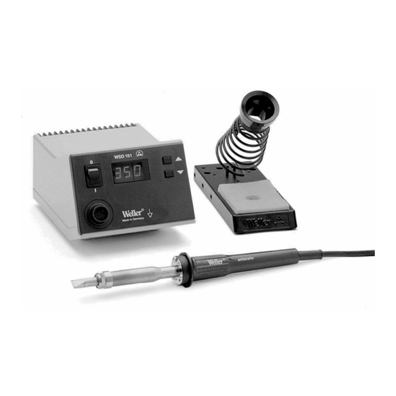
WSD 151 / PUD 151R WSD 151 / PUD 151R Geräteübersicht Netzschalter Digitalanzeige (Display) UP-Taste DOWN-Taste Optische Regelkontrolle Potentialausgleichsbuchse Anschlussbuchse für Lötkolben Netzanschluss Netzsicherung 10 Spannungswahlschalter (umschaltbar 230 V/120 V) (PUD 151R) 11 Typenschild 12 Potentialfreier Kontakt (nur PUD 151R) 13 Stecker für potentialfreien... -
Page 3: Table Des Matières
Garantie ..................10 1 Zu dieser Anleitung Wir danken Ihnen für das mit dem Kauf der Weller WSD 151 / PUD 151R erwiesene Vertrauen. Bei der Fertigung wurden strengste Qualitätsanforderungen zugrunde gelegt, die eine einwandfreie Funktion des Gerätes sicherstellen. -
Page 4: Bestimmungsgemäßer Gebrauch
4-10 WSD 151 / PUD 151R Warnhinweise in dieser Anleitung nicht beachten. Geben Sie die Lötstation WSD 151 / PUD 151R an Dritte stets zusammen mit der Bedienungsanleitung weiter. Bestimmungsgemäßer Gebrauch Verwenden Sie die Lötstation WSD 151 / PUD 151R ausschließlich gemäß... - Page 5 WSD 151/PUD 151R 5-10 Temperatur zu hoch) oder „LO“ (Low: Temperatur zu niedrig) im Zwei-Sekunden-Takt angezeigt. Die Weller Lötstation WSD 151 / PUD 151R bietet folgende weitere Funktionen: − Automatische Werkzeugerkennung Aktivierung entsprechenden Regelparameter − Digitale Temperaturregelung − Nullspannungsschaltung − Antistatische Ausführung des Gerätes nach ESD-Sicherheit −...
- Page 6 6-10 WSD 151 / PUD 151R Technische Daten WSD 151 / PUD 151R Abmessungen L x W x H (mm): 166 x 115 x 101 L x W x H (inch): 6.54 x 4.53 x 3.98 Gewicht 3.335 kg Netzspannung...
-
Page 7: Gerät In Betrieb Nehmen
− Blinken der LED signalisiert das Erreichen der vorgewählten Temperatur. Hinweis Die an das WSD 151 / PUD 151R anschließbaren Werkzeuge entnehmen Sie bitte der Zubehörliste auf der Seite 10. 6 Gerät bedienen Ohne zusätzliches Eingabegerät können Sie zwei Einstellungen am WSD 151 / PUD 151R vornehmen: −... -
Page 8: Temperatur Einstellen
8-10 WSD 151 / PUD 151R Temperatur einstellen Das Display (2) zeigt den Temperatur-Istwert an. 1. Die Taste UP (3) oder DOWN (4) drücken. Das Display schaltet auf den eingestellten Sollwert um. Die Temperaturanzeige blinkt. 2. Die Taste UP oder DOWN drücken, um die gewünschte Solltemperatur einzustellen: Permanentes Drücken verstellt den Sollwert im Schnelldurchlauf. -
Page 9: Wsd 151 / Pud 151R Pflegen Und Warten
Die Steuergeräte wurden für eine mittlere Lötspitzengröße justiert. Abweichungen durch Spitzenwechsel oder durch Verwendung von anderen Spitzenformen können entstehen. 7 WSD 151 / PUD 151R pflegen und warten Der Übergang zwischen Heizkörper / Sensor und der Lötspitze darf nicht durch Schmutz, Fremdkörper... -
Page 10: Fehlermeldungen Und Fehlerbehebung
10-10 WSD 151 / PUD 151R 8 Fehlermeldungen und Fehlerbehebung Meldung/Symptom Mögliche Ursache Maßnahmen zur Abhilfe Anzeige: "- - -“ Werkzeug wurde nicht erkannt Anschluss des Werkzeugs am Werkzeug defect Gerät überprüfen Angeschlossenes Werkzeug überprüfen Anzeige: "tip" Lötspitze des Mircotools nicht Lötspitze erneut einstecken... - Page 11 WSD 151 / PUD 151R Operating Manual...
-
Page 12: Equipment Overview
WSD 151 / PUD 151R WSD 151 / PUD 151R Equipment overview Mains switch Digital display UP button DOWN button Optical control check Equipotential-bonding socket Connecting socket for soldering iron Mains connection Mains system fuse 10 Voltage selection switch (230 V / 120 V settings) -
Page 13: About These Instructions
Always pass on the WSD 151 / PUD 151R soldering station to third parties together with these Operating Instructions. -
Page 14: Intended Use
4-10 WSD 151 / PUD 151R Intended use Use the WSD 151 / PUD 151R soldering station exclusively for the purpose indicated in the Operating Instructions of soldering and unsoldering under the conditions specified here. Specified use of the WSD 151 / PUD 151R soldering station also includes −... - Page 15 WSD 151/PUD 151R 5-10 The Weller WSD 151 / PUD 151R soldering station also offers the following functions: − Automatic tool detection and activation of corresponding control parameters − Digital temperature control − Zero voltage circuit − Antistatic device design in accordance with ESD safety −...
- Page 16 6-10 WSD 151 / PUD 151R Technical data WSD 151 / PUD 151R Dimensions L x W x H (mm): 166 x 115 x 101 L x W x H (inch): 6.54 x 4.53 x 3.98 Weight 3.335 kg Mains supply voltage...
-
Page 17: Starting Up The Device
Note Please refer to the accessories section on page 10 for a list of tools that can be connected to the WSD 151 / PUD 151R. 6 Operating the device Two settings are available on the WSD 151 / PUD 151R without an additional input unit: − Setpoint temperature setting −... -
Page 18: Setting The Temperature
8-10 WSD 151 / PUD 151R Setting the temperature The display (2) indicates the actual temperature value. 1. Press the UP (3) or DOWN (4) button. The display switches to the preset setpoint value. The temperature display flashes. 2. Press the UP or DOWN button to set the desired setpoint temperature: Permanent pressing alters the setpoint value in rapid pass mode. -
Page 19: Wsd 151 / Pud 151R Care And Maintenance
The control units have been adapted to hold a medium-sized soldering tip. Discrepancies may occur if the tip is changed or a different shaped tip is used. 7 WSD 151 / PUD 151R care and maintenance Dirt and foreign objects accumulated in the join between the heating element / sensor and the soldering tip or damage to this join may affect the accuracy of the temperature control. -
Page 20: Fault Messages And Fault Elimination
10-10 WSD 151 / PUD 151R 8 Fault messages and fault elimination Message/Symptom Possible cause Corrective measures Display: "- - -“ Tool has not been detected Check connection of tool to device Tool defective Check connected tool Display: "tip" Soldering tip of microtool not... - Page 21 WSD 151 / PUD 151R Manuel d'utilisation...
-
Page 22: Vue D'ensemble De L'appareil
WSD 151 / PUD 151R WSD 151 / PUD 151R Vue d'ensemble de l'appareil Interrupteur d'alimentation Afficheur numérique (Écran) Touche UP (vers le haut) Touche DOWN vers le bas) Contrôle de régulation optique Fiche d'équilibrage de potentiel Douille de raccordement pour fer à... -
Page 23: Pour Votre Sécurité
5 Mise en service de l'appareil ............. 7 6 Utilisation de l'appareil ............... 7 7 Entretien et maintenance de la WSD 151 / PUD 151R ..... 9 8 Messages d'erreur et élimination des défauts ......10 9 Accessoires ................10 10 Elimination des déchets ............. -
Page 24: Utilisation Conforme À L'usage Prévu
WSD 151 / PUD 151R Utilisation conforme à l'usage prévu Utilisez uniquement la station de soudage WSD 151 / PUD 151R conformément au but indiqué dans le manuel d'utilisation, pour le soudage et le dessoudage dans les conditions indiquées ici. - Page 25 WSD 151/PUD 151R 5-10 La station de soudage Weller WSD 151 / PUD 151R offre les autres fonctions suivantes : − Détection d'outil automatique et activation des paramètres de régulation correspondants − Régulation de température numérique − Commutation à zéro volt −...
-
Page 26: Caractéristiques Techniques
6-10 WSD 151 / PUD 151R Caractéristiques techniques WSD 151 / PUD 151R Dimensions L x l x H (mm) : 166 x 115 x 101 L x l x H (pouces) : 6,54 x 4,53 x 3,98 Poids 3,335 kg Tension de réseau... -
Page 27: Mise En Service De L'appareil
− Le clignotement de la diode signale que la température prédéfinie est atteinte. Remarque Veuillez consulter la liste des accessoires page 10 pour connaître les outils que l'on peut raccorder à la WSD 151 / PUD 151R. 6 Utilisation de l'appareil Sans programmateur supplémentaire, seuls deux réglages sont possibles sur la WSD 151 / PUD 151R : −... -
Page 28: Réglage De La Température
8-10 WSD 151 / PUD 151R Réglage de la température L'afficheur (2) affiche la valeur réelle de température. 1. Appuyer sur la touche UP (3) ou DOWN (4). L'afficheur commute sur la valeur de consigne réglée. L'afficheur de température clignote. -
Page 29: Réduction De Température Standard
7 Entretien et maintenance de la WSD 151 / PUD 151R La jonction entre l'élément chauffant / le capteur et la panne ne doit pas être altérée par des saletés, des corps étrangers ou des dommages, car cela nuit à... -
Page 30: Messages D'erreur Et Élimination Des Défauts
10-10 WSD 151 / PUD 151R 8 Messages d'erreur et élimination des défauts Message / symptôme Cause possible Remède Affichage "- - -" L'outil n'a pas été détecté Contrôler le raccordement de l'outil au Outil défectueux niveau de l'appareil Contrôler l'outil raccordé... - Page 31 WSD 151 – Exploded Drawing...
- Page 32 WSD 151 – Circuit Diagram...
- Page 33 PUD 151R – Exploded Drawing...
- Page 34 151R – Circuit Diagram...