Table des Matières
Publicité
Les langues disponibles
Les langues disponibles
Liens rapides
Helios Ventilatoren
MONTAGE- UND BETRIEBSVORSCHRIFT
INSTALLATION AND OPERATING INSTRUCTIONS
NOTICE DE MONTAGE ET D'UTILISATION
Rohbauset Fassade
Installation kit facia
Façade kit gros oeuvre
KWL 45 RSF
KWL 45 RSF-L
Wärmerückgewinnung und EC-Technik
für den Wandeinbau
Heat recovery and EC-motor technology for wall
installation
Récupération de chaleur et technique EC pour
montage mural
DE
EN
FR
Publicité
Chapitres
Table des Matières

Manuels Connexes pour Helios KWL 45 RSF


Sommaire des Matières pour Helios KWL 45 RSF
- Page 1 MONTAGE- UND BETRIEBSVORSCHRIFT INSTALLATION AND OPERATING INSTRUCTIONS NOTICE DE MONTAGE ET D’UTILISATION Rohbauset Fassade Installation kit facia Façade kit gros oeuvre KWL 45 RSF KWL 45 RSF-L Wärmerückgewinnung und EC-Technik für den Wandeinbau Heat recovery and EC-motor technology for wall installation Récupération de chaleur et technique EC pour...
- Page 2 DEUTSCH...
-
Page 3: Table Des Matières
Montage- und Betriebsvorschrift Rohbauset Fassade KWL 45 RSF / KWL 45 RSF-L Inhaltsverzeichnis KAPITEL 1 SICHERHEIT . . . . . . . . . . . . . . . . . . . . . . . . . . . . . . . . . . . . . . . . . . . . . . . . . . . . . . . . . . . . . . . . . . . . . Seite 3 Wichtige Informationen . -
Page 4: Wichtige Informationen
Medien, längere Stillstandzeiten, starke Verschmutzung, übermäßige Beanspruchung durch klima- tische, technische oder elektronische Einflüsse geeignet. Gleiches gilt für die mobile Verwendung der Lüftungsgeräte (Fahr-, Flugzeuge, Schiffe, usw.). Ein Einsatz unter diesen Bedingungen ist nur mit Einsatzfreigabe seitens Helios mög- lich, da die Serienausführung hierfür nicht geeignet ist. -
Page 5: Garantieansprüche - Haftungsausschluss
2 .3 Sendungsannahme Die Sendung (Rohbauset Fassade KWL 45 RSF, Best. Nr. 3005 oder KWL 45 RSF-L, Best. Nr. 3070) ist sofort bei Anlieferung auf Beschädi gungen und Typenrichtigkeit zu prüfen. Falls Schäden vorliegen, umgehend Schadensmel- dung unter Hinzuziehung des Transportunternehmens veranlassen. Bei nicht fristgerechter Reklamation gehen evtl. -
Page 6: Lieferumfang
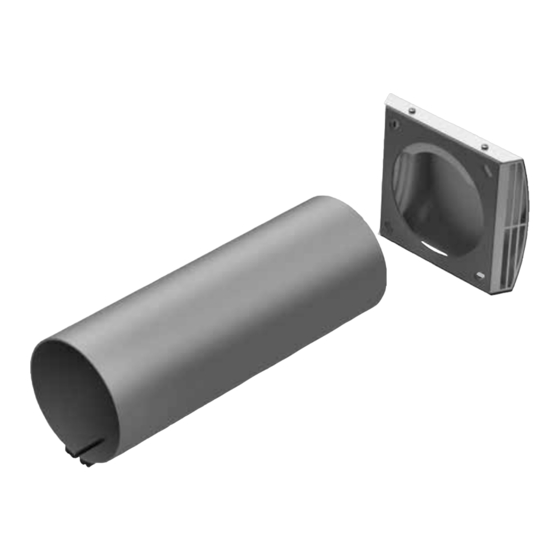
Best .-Nr . 3070 KWL 45 RSF-LB (lang) Best .-Nr . 1955 Wandeinbauhülse ò – aus Kunststoff: im Set KWL 45 RSF = 500 mm – aus Kunststoff: im Set KWL 45 RSF-L = 800 mm ä ù EPP-Frontkeil – für Kondensatgefälle ò... -
Page 7: Positionierung
Montage- und Betriebsvorschrift Rohbauset Fassade KWL 45 RSF / KWL 45 RSF-L 4 .0 Positionierung KAPITEL 4 Folgende Abstände zur Wand und Decke sind bei der Positionierung des Lüftungsgerätes bzw. der Kernlochbohrung zu beachten (Abb.4). POSITIONIERUNG/ EINBAU Abb .4 Wandabstand mind. -
Page 8: Montageschritt Aussenwand: - Fassadenblende
Montage- und Betriebsvorschrift Rohbauset Fassade KWL 45 RSF / KWL 45 RSF-L SCHNITT A-A SCHNITT A-A Einbau Wandhülse bei Montage mit Standard-Fassadenblende Abb .7 Einbau Wandhülse bei Montage mit tiefer Fassadenblende (bis auf 300 mm kürzbar) (Wandstärke) 500/800 min. 250 Innenwand Außenwand... -
Page 9: Kondensatableitung
Montage- und Betriebsvorschrift Rohbauset Fassade KWL 45 RSF / KWL 45 RSF-L 4. Blende abnehmen und Blendenrahmen zentriert über der Wandöffnung ausrichten, Bohrbild anzeichnen und bohren (Abb.12). 5. Blendenrahmen waagerecht ausrichten (Abb.12) und an der Wand festschrauben (Edelstahl-Schrauben bauseits). Anschließend die Blende wieder aufstecken und festschrauben (Abb.13). -
Page 10: Schaltplanübersicht
Montage- und Betriebsvorschrift Rohbauset Fassade KWL 45 RSF / KWL 45 RSF-L 6 .1 Schaltplanübersicht Abb .16 SS-1093 Betrieb mit bis zu 8 x KWL EC 45 mit 2 x KWL 45 SNU parallel KWL EC 45: Start Zuluft KWL EC 45: Start Abluft... - Page 11 Montage- und Betriebsvorschrift Rohbauset Fassade KWL 45 RSF / KWL 45 RSF-L Abb .17 SS-1091 Service Micro USB KWL 45 BEU 8 9 10 11 - / GND M2... - / GND M1... - / GND 12V= Schutzklasse 3, SELV-Sicherheitskleinspannung...
- Page 12 ENGLISH...
- Page 13 Installation and operating instructions Installation kit facia KWL 45 RSF / KWL 45 RSF-L Table of contents CHAPTER 1 . SAFETY . . . . . . . . . . . . . . . . . . . . . . . . . . . . . . . . . . . . . . . . . . . . . . . . . . . . . . . . . . . . . . . . . . . . . . . Page 3 Important information .
-
Page 14: Important Information
The same applies for the mobile use of fans (vehicles, aircraft, ships, etc.). Usage under these conditions is only possible with release approval from Helios, as the standard version is not suitable in this case. – Improper, prohibited use: Any use other than the intended use is not permitted! The conveying of solid matter or solid matter content >... -
Page 15: Warranty Claims - Exclusion Of Liability
CHAPTER 2 All versions of this documentation must be observed, otherwise the warranty shall cease to apply. The same applies to liability claims against Helios. The use of accessory parts, which are not recommended or offered by Helios, is not GENERAL permitted. -
Page 16: Chapter 3 Scope Of Delivery
Installation and operating instructions Installation kit facia KWL 45 RSF / KWL 45 RSF-L 3 .0 Scope of delivery CHAPTER 3 Leave the installation kit facia in its packaging until just before the respective installation step or installation in order to prevent any possible damage and contamination. -
Page 17: Positioning
Installation and operating instructions Installation kit facia KWL 45 RSF / KWL 45 RSF-L 4 .0 Positioning CHAPTER 4 The following distances to walls and ceilings must be observed when positioning the ventilation unit or core hole drilling (fig.4). POSITIONING/ INSTALLATION fig .4... - Page 18 Installation and operating instructions Installation kit facia KWL 45 RSF / KWL 45 RSF-L SCHNITT A-A SCHNITT A-A Wall installation with standard facade panel Abb .7 Wall installation with deep facade panel (Shortened up to 300 mm) (bis auf 300 mm kürzbar) (Wandstärke)
-
Page 19: Condensate Drainage
Installation and operating instructions Installation kit facia KWL 45 RSF / KWL 45 RSF-L 4. Remove panel and position the panel frame centrally over the wall opening, mark the drill holes and drill (fig.12). 5. Place panel frame in horizontal position (fig.12) and screw into the wall (stainless steel screws must be provided on site). -
Page 20: Circuit Diagram Overview
Installation and operating instructions Installation kit facia KWL 45 RSF / KWL 45 RSF-L 6 .1 Circuit diagram overview fig .16 SS-1093 Betrieb mit bis zu 8 x KWL EC 45 mit 2 x KWL 45 SNU parallel KWL EC 45: Start Zuluft... - Page 21 Installation and operating instructions Installation kit facia KWL 45 RSF / KWL 45 RSF-L fig .17 SS-1091 Service Micro USB KWL 45 BEU 8 9 10 11 - / GND M2... - / GND M1... - / GND 12V= Schutzklasse 3,...
- Page 22 FRANÇAIS...
- Page 23 Notice de montage et d’utilisation Façade kit gros oeuvre KWL 45 RSF / KWL 45 RSF-L Sommaire CHAPITRE 1 . SÉCURITÉ . . . . . . . . . . . . . . . . . . . . . . . . . . . . . . . . . . . . . . . . . . . . . . . . . . . . . . . . . . . . . . . . . . . . Page 3 Informations importantes .
-
Page 24: Chapitre 1 . Sécurité
à des contraintes techniques et électroniques. Une demande d’approbation est donc requise par Helios : les modèles de série n’étant pas prévus pour cet usage. Idem pour le déplacement des ventilateurs (voitures, avions, bateaux, etc.). -
Page 25: Chapitre 2 . Informations Générales
Réception de la marchandise Dès réception, vérifier l’état et la conformité du matériel commandé (façade kit gros oeuvre KWL 45 RSF, réf. n°3005 et KWL 45 RSF-L, réf. n°3070). En cas d’avaries, des réserves doivent être portées sur le bordereau du transporteur. -
Page 26: Chapitre 3 . Commande
Notice de montage et d’utilisation Façade kit gros oeuvre KWL 45 RSF / KWL 45 RSF-L 3 .0 Contenu de la livraison CHAPITRE 3 Pour éviter d‘endommager ou de salir les pièces, nous vous conseillons de sortir le kit de façade gros oeuvre et ses COMMANDE accessoires de son emballage qu‘au moment de la mise en oeuvre de chaque pièce. -
Page 27: Chapitre 4 . Positionnement
Notice de montage et d’utilisation Façade kit gros oeuvre KWL 45 RSF / KWL 45 RSF-L 4 .0 Positionnement CHAPITRE 4 Les distances mur/plafond suivantes sont à respecter lors du positionnement de l’unité de ventilation et du carrotage (fig. 4). -
Page 28: Évacuation Des Condensats
Notice de montage et d’utilisation Façade kit gros oeuvre KWL 45 RSF / KWL 45 RSF-L SCHNITT A-A SCHNITT A-A Fig .7 d’intégration murale devra dépasser de 50 mm (rétractable jusqu’à 300 mm) (bis auf 300 mm kürzbar) (Wandstärke) 500/800 min. -
Page 29: Chapitre 6 . Raccordement Électrique
Notice de montage et d’utilisation Façade kit gros oeuvre KWL 45 RSF / KWL 45 RSF-L 4. Retirer la grille et centrer le cadre de la grille sur l‘ouverture du mur, tracer les trous à forer et percer (fig. 12). - Page 30 Notice de montage et d’utilisation Façade kit gros oeuvre KWL 45 RSF / KWL 45 RSF-L 6 .1 Plan de raccordement Fig . 16 SS-1093 Utilisation jusqu’à 8x KWL EC 45 avec en paralèlle 2x KWL 45 SNU KWL EC 45: Démarrage soufflage KWL EC 45: Démarrage reprise...
- Page 31 Notice de montage et d’utilisation Façade kit gros oeuvre KWL 45 RSF / KWL 45 RSF-L Fig . 17 SS-1091 Service Micro USB KWL 45 BEU 8 9 10 11 - / GND M2... - / GND M1... - / GND...
- Page 32 HELIOS Ventilatoren GmbH + Co KG · Lupfenstraße 8 · 78056 VS-Schwenningen HELIOS Ventilateurs · Le Carré des Aviateurs · 157 avenue Charles Floquet · 93155 Le Blanc Mesnil Cedex CH HELIOS Ventilatoren AG · Tannstrasse 4 · 8112 Otelfingen GB HELIOS Ventilation Systems Ltd.