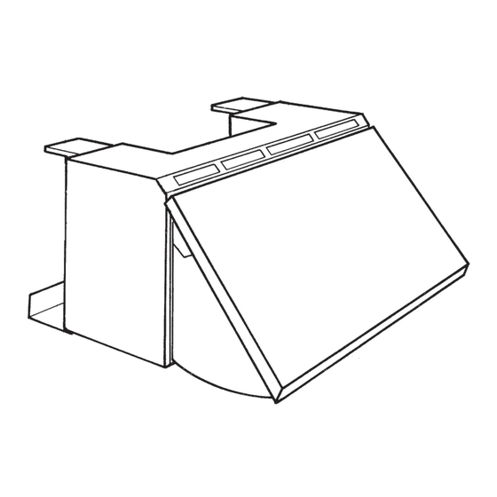
Sommaire des Matières pour ROBLIN Open 610
- Page 1 Open 610 Instructions Booklet Mode d’emploi Bedienungsanleitung Gebruiksaanwijzing 2108...
-
Page 2: Table Des Matières
Contenents - Sommaire FOR THE USER ...................... 4 DEFINITION ........................4 Important Recommendations ..................4 USAGE .......................... 5 MAINTENANCE......................5 FOR THE INSTALLER .................... 6 INSTALLATION ......................6 EVACUATION DIRECTLY OUTDOORS ................ 8 EVACUATION BY RECYCLING ..................9 ELECTRICAL CONNECTION ..................10 POUR L’UTILISATEUR .................. - Page 3 Inhalt - Inhoud FÜR DEN BENUTZER................... 18 DEFINITION ........................ 18 WICHTIGE HINWEISE ....................18 BEDIENUNG ....................... 19 WARTUNG ........................19 FÜR DEN INSTALLATEUR ................... 20 MONTAGE ........................20 DIREKTER ABZUG NACH AUSSEN ................23 UMLUFTBETRIEB ....................... 23 ELEKTRISCHER ANSCHLUSS .................. 24 VOOR DE GEBRUIKER ..................
-
Page 4: For The User
FOR THE USER Now that your cooker hood has been installed in accordance with the “For the Fitter” part of these instructions by an authorized specialist, please read the following pages carefully. This will help you to become familiar with and to make the best use of the features of your appliance. DEFINITION - These appliance are extendable hoods designed to be installed in the place of a tall 60 cm wide kitchen unit. -
Page 5: Usage
USAGE The hood is fitted with a control box behind the opening, containing 3 controlside (fig.1). - Slide “L” is used to switch the lighting on and off. - Slide “M” is used to start or stop the fan, confirmed by a power on indicator. - Slide “V”... -
Page 6: For The Installer
- Each filter is supplied with installation instructions. Panelwork Use lukewarm water only, to which a non-aggressive cleaning liquid is added. Do not use abrasive or aggressive products, or products containing alcohol. Lighting - Lighting is provided by two 40 W bulbs. - To replace them, remove the grease filters as described in the “Grease filter”... - Page 7 - The hood depth can be adjusted between 27 and 36 cm. Depth adjustment: 1 - Measure the body depth of the furniture between which the hood is to be installed. 2 - Loosen the hexagonal bolts for the adjustment of the upper suspension hooks (fig.
-
Page 8: Evacuation Directly Outdoors
Installing the evacuation duct - Depending on the choice of evacuation ducts, install the 100 or 120 mm Ø duct which attaches to the rear box by a bayonet system. Connection There is an adjustment lever inside the hood (fig. 4) for selecting “evacuation” or “recycling”... -
Page 9: Evacuation By Recycling
EVACUATION BY RECYCLING - Put the adjustment lever to the recycling position (down) and after installing the active carbon filter (as described in the installation part of these instructions and in accordance with the instructions attached to the recycling kit) the recycled air is discharged through the louvers at the top of the hood facade. -
Page 10: Electrical Connection
ELECTRICAL CONNECTION - Connect the appliance cord to a 10/16 A standard grounded power outlet (2 pins + earthing pin), preferably located above the hood. - If the power outlet is not permanently accessible, a 3-pole switch will have to be provided in the installation with a minimum contact opening of 3 mm. -
Page 11: Pour L'utilisateur
POUR L’UTILISATEUR Votre appareil ayant été installé suivant les recommandations de la partie installateur de cette notice par un spécialiste, nous vous remercions de bien vouloir lire attentivement les pages qui suivent. Cette lecture vous permettra de bien connaître et d’utiliser au mieux les possibilités de votre appareil. -
Page 12: Utilisation
UTILISATION La hotte est équipée d’un boîtier de commande situé à droite derrière l’ouvertu- re, avec 3 curseurs de commande (fig. 1). - Le curseur “L” permet d’allumer et d’éteindre l’éclairage. - Le curseur “M” permet la marche ou l’arrêt du ventilateur, confirmé... -
Page 13: Pour L'installateur
- Chaque filtre est livré avec sa notice de montage. Carrosserie Utilisez exclusivement de l’eau tiède additionnée d’un liquide de nettoyage non agressif. Ne pas utiliser de produits abrasifs ou contenant de l’alcool. Eclairage - L’éclairage est réalisé par 2 ampoules (40 W). - Pour les remplacer, enlevez les filtres anti- grasseis comme expliqué... - Page 14 Préparation de la hotte - Avant de procéder au montage mural, il est nécessaire d’adapter la profondeur de la hotte à celle des meubles adjacents. - La profondeur de la hotte peut être réglée de 27 à 36 cm. Réglage de la profondeur: 1 - Mesurez la profondeur du corps des meubles entre lesquels la hotte doit être installée.
-
Page 15: Evacuation Directe Vers L'extérieur
Fixation complémentaire aux meubles adjacents - Après avoir retiré les filtres anti-graisses, utilisez les trous apparents dans les parois latérales pour la fixation sur les meubles adjacents. (Le gabarit fourni peut être utilisé avant le montage mural). Montage de la buse d’évacuation - Suivant le choix des conduits d’évacuation, mettre en place la buse d’évacuation Ø... -
Page 16: Evacuation En Recyclage
- Cette ventouse de section carrée a été spécialement conçue pour les hottes et s’encastre dans tout mur extérieur d’une épaisseur comprise entre 23 et 43 cm. - Des jalousies extérieures empêchent vents et pluies de pénétrer et un rebord (jet d’eau) à... -
Page 17: Raccordement Électrique
RACCORDEMENT ÉLECTRIQUE - Branchez le cordon de l’appareil sur une prise de courant normalisée de 10/16 A raccordée à la terre (2P + T) et située de préférence au dessus de la hotte. - Si la prise de courant n’est pas accessible en permanence, il est nécessarie de prévoir dans l’installation un interrupteur omnipolaire ayant une ouverture de contact de 3 mm minimum. - Page 18 This appliance complies with European regulations on low voltages, EEC Directive 73/23 on electrical safety, and with the following European regulations: EEC Directive 89/336 on electromagnetic compatibility and EEC Directive 93/68 on EC marking. Cet équipement est conforme à la norme européenne sur la basse tension C.E.E. 73/23 relative à...


