Urmet 1722 Notice D'installation Et D'utilisation
Masquer les pouces
Voir aussi pour 1722:
- Manuel d'installation et d'utilisation (20 pages) ,
- Manuel d'instructions (14 pages) ,
- Mode d'emploi (13 pages)
Table des Matières
Publicité
Les langues disponibles
Les langues disponibles
DS 1722-139
KIT VIDEO 2 FILI MONO E BIFAMILIARE MÌRO VIVAVOCE / MIKRA2
ONE- AND TWO-HOUSEHOLD 2 WIRES VIDEO KIT WITH HANDS-FREE
KIT VIDÉO 2 FILS MONO ET BI-FAMILLE MÌRO MAINS LIBRES / MIKRA2
(La documentación en español, alemán y fl amenco está disponible
escaneando el siguiente código QR)
(Die spanische, deutsche und Flämisch Dokumentation kann durch
Scannen des folgenden QR-Codes abgerufen werden)
(Spaanse, Duitse en Vlaams documentatie is beschikbaar door de
volgende QR-code te scannen)
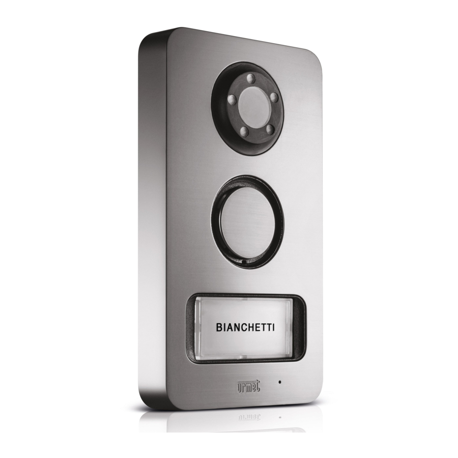
MÌRO AND MIKRA2 PANEL
Sch./Ref. 1722/93 - 1722/94
LIBRETTO DI INSTALLAZIONE ED USO
INSTALLATION AND USE MANUAL
NOTICE D'INSTALLATION ET D'UTILISATION
IP55
IK07
(*)
Mod.
1722
LBT 20827
(*)
(*)
(*)
Publicité
Chapitres
Table des Matières

Manuels Connexes pour Urmet 1722


Sommaire des Matières pour Urmet 1722
- Page 1 KIT VIDEO 2 FILI MONO E BIFAMILIARE MÌRO VIVAVOCE / MIKRA2 ONE- AND TWO-HOUSEHOLD 2 WIRES VIDEO KIT WITH HANDS-FREE MÌRO AND MIKRA2 PANEL KIT VIDÉO 2 FILS MONO ET BI-FAMILLE MÌRO MAINS LIBRES / MIKRA2 Sch./Ref. 1722/93 - 1722/94 IP55 IK07 LIBRETTO DI INSTALLAZIONE ED USO INSTALLATION AND USE MANUAL NOTICE D’INSTALLATION ET D’UTILISATION...
-
Page 2: Table Des Matières
12.1 Collegamento del kit monofamiliare Sch. 1722/93 con 3 videocitofoni in parallelo ....62 12.2 Collegamento del kit bifamiliare Sch. 1722/94 con 3 videocitofoni in parallelo ad ogni utenza ..63 12.2.1 Esempio di collegamento al kit di una badenia per la ripetizione della chiamata ... 64 12.2.2 Esempio di collegamento al kit di due serrature elettriche con apertura contemporanea ... -
Page 3: Descrizione Generale
DESCRIZIONE GENERALE I kit videocitofonici Mod. 1722/93 e /94 sono caratterizzati dalla semplicità di installazione grazie all’utilizzo di 2 soli fi li non polarizzati per l’interconnessione tra i vari dispositivi. Le caratteristiche del sistema videocitofonico sono le seguenti: Sistema •... -
Page 4: Composizione Del Kit
COMPOSIZIONE DEL KIT Descrizione N° Pulsantiera mod. Mikra2 con 1 tasto di chiamata (presente solo nel kit Sch. 1722/93) Pulsantiera mod. Mikra2 con 2 tasti di chiamata (presente solo nel kit Sch. 1722/94) Viti per fi ssaggio a parete Postazione di chiamata Tasselli per fi... -
Page 5: Dispositivi Accessori
Serratura elettrica (12 V~ Max 15 VA) Suoneria supplementare Sch.9854/43 Videocitofoni supplementari Mod. Mìro “Slave” Sch.1722/88 (in quantità 3 con il kit Sch.1722/93, in quantità 6 con il kit Sch.1722/94) Pulsante androne per azionamento serratura elettrica pedonale Pulsante androne per azionamento apriporta passo carraio... -
Page 6: Parti Di Ricambio
Pulsantiera mod. Mikra2 con 2 tasti di chiamata (presente solo nel kit Sch. Sch.1722/116 1722/94) Induttanza elettronica Sch.1722/112 Alimentatore Sch.1722/21 Pulsante di ricambio per pulsantiera Sch.1722/114 Bifamiliare Videocitofono Mìro Master/Slave Sch.1722/88 B/OP3 Distributore video Sch.1722/55 (Solo nel kit Sch.1722/94) DS1722-139... -
Page 7: Schema A Blocchi Di Collegamento
SCHEMA A BLOCCHI DI COLLEGAMENTO 5.1. IMPIANTO MONOFAMILIARE Master Slave Slave 110/230 V~ Slave (1) Per le confi gurazioni dei dip-switch vedere par. 7.2 CONFIGURAZIONE DIP-SWITCH La suoneria supplementare OP2 può essere collegata indifferentemente su qualunque videocitofono dell’impianto. 5.1.1. DISTANZE MASSIME TRA I DISPOSITIVI Impianto base con 1 videocitofono Tipo di cavo Cavo... -
Page 8: Impianto Bifamiliare
5.2. IMPIANTO BIFAMILIARE Master 1 Master 2 Slave Slave Famiglia Famiglia 110/230 V~ Slave Slave (1) Per le confi gurazioni dei dip-switch vedere par. 7.2 CONFIGURAZIONE Slave Slave DIP-SWITCH La suoneria supplementare OP2 può essere collegata indifferentemente su qualunque videocitofono dell’impianto. 5.2.1. -
Page 9: Avvertenze Per L'installatore
AVVERTENZE PER L’INSTALLATORE Leggere attentamente le avvertenze contenute nel presente documento in quanto forniscono importanti indicazioni riguardanti la sicurezza di installazione, uso e manutenzione. • I dispositivi facenti parte del kit dovranno essere destinati solo all’uso per il quale sono stati espressamente concepiti. -
Page 10: Installazione Del Videocitofono
INSTALLAZIONE DEL VIDEOCITOFONO Murare la scatola incasso all’altezza indicata nel disegno seguente. Fissare la staffa alla scatola incasso o a muro come indicato. Programmare i dip-switch di programmazione. Scatola Mod.503 Scatola Ø 60 mm n° 2 M3,5 x 19 mm n°... -
Page 11: Associazione Pulsante Di Chiamata A Videocitofono
7.4. PROGRAMMAZIONE DELLA FUNZIONE INTERCOMUNICANTE E’ possibile programmare 2 pulsanti ( ) per effettuare le chiamate intercomunicanti. Con il kit sch. 1722/93 è possibile chiamare fi no a 2 videocitofoni nello stesso appartamento. Con il kit sch. 1722/94 è possibile chiamare in alternativa: •... -
Page 12: Installazione Dell'alimentatore
INSTALLAZIONE DELL’ALIMENTATORE Alimentatore in CAT II 2500 V. L’alimentatore che, una volta installato, è soggetto a tensioni transitorie superiori a quelle della categoria di sovratensione di progetto, necessita di una protezione supplementare delle tensioni transitorie esterne all’apparecchiatura. L’alimentatore deve essere installato all’interno di un quadro elettrico oppure di un armadietto. Installazione ad appoggio parete Installazione su barra DIN (6 moduli da 18 mm) -
Page 13: Descrizione Dei Morsetti
8.2. DESCRIZIONE DEI MORSETTI Alimentatore Sch. 1722/21 Ingresso tensione di alimentazione di rete 110/230 V~ Uscita tensione di alimentazione Modulo induttanza elettronica Sch. 1722/112 Ingresso tensione di alimentazione LINE1 Linea BUS 1 LINE2 Linea BUS 2 DS1722-139... -
Page 14: Installazione Della Postazione Di Chiamata
INSTALLAZIONE DELLA POSTAZIONE DI CHIAMATA 9.1. DESCRIZIONE DEI COMPONENTI VISTA FRONTALE Pulsantiera con 1 tasto Pulsantiera con 2 tasti di chiamata Sch. 1722/115 di chiamata Sch. 1722/116 (Kit Sch. 1722/93) (Kit Sch. 1722/94) Altoparlante Led di illuminazione telecamera Telecamera Cartellino/i portanome... -
Page 15: Modalità Di Installazione
9.2. MODALITÀ DI INSTALLAZIONE • Installare la pulsantiera all’altezza indicata verifi cando che il soggetto rientri nel campo inquadrato dalla telecamera; • Collegare i fi li alla morsettiera; • Montare i cartellini portanome sul frontale; • Eseguire le programmazioni; • Regolare il livello fonico;... -
Page 16: Descrizione Dei Morsetti
9.3. DESCRIZIONE DEI MORSETTI Morsetti per pulsante per serratura elettrica pedonale (OP4) Morsetti per pulsante per apriporta passo carraio (OP5) Contatto pulito azionamento apriporta passo carraio (OP6) - massima commutazione 1 A @ 30 V Linea BUS Azionamento serratura elettrica pedonale (OP1) - massima commutazione 12 V~ 15 VA 9.4. -
Page 17: Regolazione Livello Fonico Altoparlante
9.6. REGOLAZIONE LIVELLO FONICO ALTOPARLANTE I livelli fonici sono tarati di fabbrica in modo da non dover essere variati nella maggioranza delle installazioni. Qualora fosse necessario modifi carli, agire con un cacciavite sull’apposita regolazione del volume dell’altoparlante. non variare la posizione di questo trimmer 10. -
Page 18: Funzione Pulsanti
10.1.1 Funzione pulsanti ATTESA Stato STATO DI PROGRAMMAZIONE RIPOSO E TASTO SGANCIO RIPOSO IN FONIA (SOLO CON VIDEOCITOFONO A (ricezione PREMUTO RIPOSO) chiamata) Pulsante [Conferma associazione Apriporta Apriporta Apriporta pedonale funzione intercom pedonale pedonale fra videocitofoni] Se premuto Attivazione brevemente della fonia attiva o termina la conversazione... -
Page 19: Gestione Della Chiamata Intercomunicante
conversare con il chiamante per un tempo massimo di 3 minuti (la conversazione può essere interrotta in qualunque momento ripremendo il tasto Durante il periodo in cui la fonia è attiva i led di retroilluminazione del cartellino portanome della postazione di chiamata si spengono. 10.3. -
Page 20: Esclusione Del Tono Di Chiamata
10.7. ESCLUSIONE TONO DI CHIAMATA È possibile regolare il volume di chiamata fi no ad escludere la suoneria (Mute) agendo sul cursore a slitta 1 (vedere par. 10.1 DESCRIZIONE FRONTALE DEL VIDEOCITOFONO). Lo stato di mute è evidenziato da un’indicazione di colore rosso visibile nella parte alta del cursore. Se il cursore è... -
Page 21: Legenda Simboli
Potenza assorbita in funzione: ..................... max 10,4 W Dimensioni (LxPxH): ......................100 x 180 x 28 mm Dimensioni cartellino portanome: ....................48 x 15 mm Illuminazione cartellini e pulsanti: ....................LED bianchi Grado di protezione degli involucri: ......................IP55 Grado di protezione contro gli impatti meccanici: ................... IK07 Temperatura di funzionamento: .................... - Page 22 11.1 Key to simbols ..........................41 12 CONNECTION DIAGRAMS ........................62 12.1 Connection of one-household kit Ref. 1722/93 with 3 video door phones in parallel ....62 12.2 Connection of two-household kit Ref. 1722/94 with 3 video door phones in parallel for each user ..........................
-
Page 23: General Description
GENERAL DESCRIPTION The Video Door Phone kits model Mod. 1722/93 and /94 are easy to install: only two non-polarised wires are needed to interconnect all system devices. The features of the video door phone system are: System • One-household (Ref. 1722/93) and two-household (Ref. 1722/94) hands-free colour video door phone kit;... -
Page 24: Kit Composition
Calling station Bolts for fastening to wall Ø 5mm (0.20'') Screwdriver insert Name tag (quantity: 1 in kit Ref.1722/93, quantity: 2 in kit Ref.1722/94) Spare Allen screw for closing calling station Mìro “Master” video door phone (quantity: 1 in kit Ref.1722/93, quantity: 2 in kit Ref.1722/94) -
Page 25: Accessory Devices
Electric lock (12V~ Max 15VA) Supplementary ringer Ref.9854/43 Additional video door phones Model Mìro “Slave” Ref.1722/88 (3 units with kit Ref.1722/93, 6 units with kit Ref.1722/94) Hall button for operating pedestrian gate electric lock Hall button for operating garage gate lock... -
Page 26: Spare Parts
SPARE PARTS Description Mikra 2 Panel with 1 calling button Ref. 1722/115 (only in kit Ref.1722/93) Mikra 2 Panel with 2 calling buttons Ref. 1722/116 (only in kit Ref.1722/94) Electric inductor Ref.1722/112 Power supply units Ref.1722/21 Replacement button for two-household Ref.1722/114... -
Page 27: Connection Block Chart
CONNECTION BLOCK CHART 5.1. ONE-HOUSEHOLD SYSTEM Master Slave Slave 110/230 V~ Slave (1) For dip-switch confi gurations see par. 7.2 DIP-SWITCH CONFIGURATION The OP2 supplementary ringer may be connected to any video door phone in the system. 5.1.1. MAXIMUM DISTANCES BETWEEN DEVICES Basic system with 1 video door phone Type of wire SYT1... -
Page 28: Two-Household System
5.2. TWO-HOUSEHOLD SYSTEM Master 1 Master 2 Slave Slave Household Household 110/230 V~ Slave Slave (1) For dip-switch confi gurations par. DIP-SWITCH CONFIGURATION Slave Slave The OP2 supplementary ringer may be connected to any video door phone in the system. 5.2.1. -
Page 29: Warnings For Installers
WARNINGS FOR INSTALLERS Read the notes in this manual carefully. This manual contains important information on safe installation, use and maintenance. • This devices in the kit must only be put to the use for which they were intended. All other use is improper. -
Page 30: Video Door Phone Installation
VIDEO DOOR PHONE INSTALLATION Install fl ush-mounting box at the height indicated in the drawing below. Fix the bracket to the mounting box or to the wall as indicated. Program the dip switches. Box Mod. 503 Box Ø 60 mm / 2.36'' n°... -
Page 31: Line Terminal
The system offers the option of programming 2 buttons (1 ) to make intercom calls. With the kit Ref. 1722/93 you can call up to 2 video door phones in the same apartment. With the kit Ref. 1722/94 you have two calling options: •... -
Page 32: Power Supply Installation
POWER SUPPLY UNIT INSTALLATION Power supply in CAT II 2500 V. Once installed, the power supply is subject to transient voltages higher than those of the overvoltage category for which is was designed. For this reason, an additional transient voltage protection is required outside the device. -
Page 33: Description Of Terminals
8.2. DESCRIPTION OF TERMINALS Power supply unit Ref. 1722/21 Mains power voltage input 110/230 V~ Power voltage output Electronic inductor module Ref. 1722/112 Power voltage input LINE1 BUS line 1 LINE2 BUS line 2 DS1722-139... -
Page 34: Calling Station Installation
9.1. DESCRIPTION OF COMPONENTS FRONT VIEW Panel with 1 calling button Panel with 2 calling buttons Ref. 1722/115 Ref. 1722/116 (Kit Ref. 1722/93) (Kit Ref. 1722/94) 1. Speaker 2. Camera lighting LED 3. Camera 4. Name tag(s) 5. Calling button(s) 6. -
Page 35: Installation Metod
9.2. INSTALLATION METOD • Install the panel at the indicated heights checking that the caller is framed by the camera. • Connect the wires to the terminal board. • Fit the name tags on the removable front. • Program. • Adjust the sound level;... -
Page 36: Description Of The Terminala
9.3. DESCRIPTION OF THE TERMINALS Hall button terminals for pedestrian electric lock (OP4) Hall button terminals for garage gate lock (OP5) Garage gate opener operation dry contact (OP6) - maximum switch 1 A @ 30 V BUS line Pedestrian electric lock operation (OP1) - maximum switch 12 V~ 15 VA 9.4. -
Page 37: Speaker Sound Level Adjustment
9.6. SPEAKER SOUND LEVEL ADJUSTMENT Volumes are calibrated by default so not to require adjustments in most cases. Use a screwdriver to adjust the speaker volume, if required. do not change the position of this trimmer 10. OPERATION 10.1. DESCRIPTION OF THE FRONT OF THE VIDEO DOOR PHONE MUTE Call volume adjustment (MAX, MEDIUM;... -
Page 38: Button Functions
10.1.1 Button functions State WAITING STAND-BY STATE OF PROGRAMMING* FOR PICK-UP DURING AUDIO AND BUTTON STAND-BY (ONLY WITH VIDEO DOOR (RECEIVING OPERATION PHONE IN STAND-BY). PRESSED CALL) Button [Confirm association of Open pedestrian Open pedestrian Open pedestrian intercom function between door door door... -
Page 39: Intercom Call Management
10.3. INTERCOM CALL MANAGEMENT To make an intercom call: • Press button , which will start blinking green; • Press to send the call to the video door phone with which you want to establish a conversation (see the procedure for programming the buttons under par. 7.4 PROGRAMMING THE INTERCOM FUNCTION);... -
Page 40: Video Door Phone Call Tone Selection
10.9. VIDEO DOOR PHONE CALL TONE SELECTION In systems with several video door phones, it may be useful to differentiate the call tone of the various devices. • To access the call tone selection menu with the system in standby, press and hold for more than 5 seconds;... -
Page 41: Key To Simbols
11.1. KEY TO SIMBOLS Symbol Description Direct input voltage Alternating input voltage Power supply fi tted with double insulator See the installation manual of the device DANGER - Presence of dangerous voltages DANGER - Presence of safety-critical components DS1722-139... - Page 42 11.1 Légendes symboles ........................61 12 SCHÉMAS DE RACCORDEMENT ......................62 12.1 Branchement du kit monofamille Réf. 1722/93 avec 3 moniteurs en parallèle ......62 12.2 Branchement du kit bi-famille Réf. 1722/94 avec 3 moniteurs en parallèle sur chaque utilisateur ............................. 63 12.2.1 Exemple de raccordement au kit d’une sonnerie à...
-
Page 43: Description Generale
DESCRIPTION GENERALE Les kits vidéoportiers Mod. 1722/93 et /94 se caractérisent par leur simplicité d’installation et grâce à l’utilisation de 2 fi ls seulement non polarisés pour l’interconnexion des différents dispositifs. Le système de vidéo possède les caractéristiques suivantes: Système •... -
Page 44: Composition Du Kit
Chevilles de fi xation murale Ø 5mm (0.20'') Embout pour tournevis Etiquette porte-nom (en quantité de 1 dans le kit Réf.1722/93, en quantité de 2 dans le kit Réf.1722/94) Vis à six pans pour la fermeture de la plaque de rue Moniteur Mod. -
Page 45: Dispositifs Auxiliaires
Serrure électrique (12V~ Max 15VA) Sonnerie supplémentaire fi laire Réf.9854/43 Moniteur supplémentaire Mod. Mìro « Esclave » (3 avec le kit Réf. 1722/93, 6 avec le kit Réf. Réf.1722/88 1722/94) Bouton de sortie pour activier la serrure électrique Bouton de sortie pour activier l’ouverture du portail Dispositif d’activation ouvre-porte d’accès... -
Page 46: Pièces De Rechange
Plaque modèle MIKRA2 avec 2 touches d’appel (uniquement dans le kit Réf. Réf.1722/116 1722/94) Adaptateur bus 2 fi ls Réf.1722/112 Alimentation Réf.1722/21 Bouton de rechange pour plaque de rue Réf.1722/114 bi-famille Moniteur Mìro Maître/Esclave Réf.1722/88 B/OP3 Distributeur vidéo Réf.1722/55 (uniquement avec le kit Réf.1722/94) DS1722-139... -
Page 47: Synoptique De Connexion
SYNOPTIQUE DE CONNEXION 5.1. INSTALLATION MONOFAMILLE Maître Esclave 110/230 V~ Esclave Esclave (1) Pour la confi guration des commutateurs, voir par. 7.2 CONFIGURATION COMMUTATEUR. La sonnerie supplémentaire OP2 peut être indifféremment raccordée à n’importe quel moniteur de l’installation. 5.1.1. DISTANCES MAXIMALES ENTRE LES DISPOSITIFS Installation de base avec 1 moniteur Type de câble Cable... -
Page 48: Installation Bi-Famille
5.2. INSTALLATION BI-FAMILLE Maître 1 Maître 2 Esclave Esclave Famille Famille 110/230 V~ Esclave Esclave (1) Pour la confi guration des commutateurs, voir par. 7.2 CONFIGURATION COMMUTATEUR. Esclave Esclave La sonnerie supplémentaire OP2 peut être indifféremment raccordée à n’importe quel moniteur de l’installation. -
Page 49: Avertissements Pour L'installateur
AVERTISSEMENTS POUR L’INSTALLATEUR Lire attentivement les instructions contenues dans le présent document, car elles fournissent d’importantes indications pour la sécurité d’installation, d’utilisation et d’entretien. • Les dispositifs inclus dans le kit doivent être exclusivement destinés à l’utilisation pour laquelle ils ont été... -
Page 50: Installation Du Moniteur
INSTALLATION DU MONITEUR Encastrer le boîtier à la hauteur indiquée dans la fi gure suivante. Fixer l’étrier au boîtier encastrable ou à la paroi, comme indiqué. Régler les commutateurs de programmation. Boîtier Mod.503 Boîtier Ø 60 mm / 2.36'' n° 2 M3,5 x 19 mm n°... -
Page 51: Association Bouton D'appel Aux Moniteurs
Il est possible de programmer 2 boutons ( ) pour effectuer les appels d’intercommunication. Avec le kit réf. 1722/93, il est possible d’appeler 2 moniteurs dans le même appartement. Avec le kit réf. 1722/94, comme alternative, il est possible d’appeler: •... -
Page 52: Installation De L'alimentation Du Système
INSTALLATION DE L’ALIMENTATION Alimentation en CAT II 2500 V. L’alimentateur, qui une fois installé peut subir des tensions transitoires supérieures à celles de la catégorie de surtension de projet, nécessite une protection supplémentaire des tensions transitoires externes à l’équipement. Le dispositif doit être installé à l’intérieur d’un tableau ou d’une armoire électrique. Installation murale en apparent Installation sur rail DIN (6 modules de 18 mm / 0.71'') -
Page 53: Description Des Bornes
8.2. DESCRIPTION DES BORNES Alimentation Réf. 1722/21 Entrée tension d’alimentation secteur 110/230 V~ Sortie tension d’alimentation Adaptateur bus 2 fi ls Réf. 1722/112 Entrée tension d’alimentation LINE1 Ligne BUS 1 LINE2 Ligne BUS 2 DS1722-139... -
Page 54: Installation De La Plaque De Rue
INSTALLATION DE LA PLAQUE DE RUE 9.1. DESCRIPTION DES COMPOSANTS FAÇADE Plaque de rue avec 1 touche Plaque de rue avec 2 touches d’appel Réf. 1722/115 d’appel Réf. 1722/116 (Kit Réf. 1722/93) (Kit Réf. 1722/94) 1. Haut-parleur 2. Diode d’éclairage caméra 3. -
Page 55: Modalites D'installation
9.2. MODALITES D’INSTALLATION • Installer la plaque de rue à la hauteur indiquée vérifi er que le sujet rentre dans le champ encadré par la caméra; • Brancher les fi ls sur les borniers; • Installer les étiquettes des noms sur la façade; •... -
Page 56: Description Des Bornes
9.3. DESCRIPTION DES BORNES Bornes pour bouton de sortie pour serrure électrique piétonne ( OP4 ) Bornes pour bouton de sortie pour ouverture portail ( OP5 ) Contact sec de commande d’accès véhicules (OP7) – commutation maximale 1A @ 30V Ligne BUS Commande de serrure électrique (OP1) –... -
Page 57: Réglage Du Niveau Phonique Du Haut-Parleur
9.6. RÉGLAGE DU NIVEAU PHONIQUE DU HAUT-PARLEUR Les niveaux phoniques sont réglés en usine et ne doivent pas être modifi és dans la plupart des installations. Si une modifi cation est nécessaire, agir sur le réglage du volume du haut-parleur à l’aide d’un tournevis. Ne pas changer la position de ce potentiomètre 10. -
Page 58: Fonctions Des Touches
10.1.1 Fonctions des touches Etat ATTENTE ETAT DE REPOS ET TOUCHE DECROCHAGE PROGRAMMATION REPOS PHONIE (RECEPTION (UNIQUEMENT SI MONITEUR ENFONCEE APPEL) AU REPOS) Touche [Confirmation de Ouvre-porte Ouvre-porte l’association de la fonction Ouvre-porte piétons piétons piétons intercom entre moniteurs] Brièvement Activation de la enfoncé, active phonie... -
Page 59: Gestion De L'appel Intercommunication
10.3. GESTION DE L’APPEL INTERCOMMUNICATION Pour effectuer un appel intercommunication: • Appuyer sur le bouton qui se met ensuite à clignoter sur le vert; • Appuyer sur le bouton pour envoyer l’appel au moniteur avec lequel on entend établir une conversation (voir la procédure boutons au § 7.4 PROGRAMMATION DE LA FONCTION INTERCOMMUNICATION);... -
Page 60: Sonnerie Additionnelle
10.8. SONNERIE ADDITIONNELLE Les moniteurs sont équipés d’une paire de bornes ( K, Z ) pour le raccordement d’une sonnerie supplémentaire. Cette sonnerie est activée en même temps que n’importe quelle tonalité d’appel. 10.9. CHOIX DE LA TONALITÉ D’APPEL DU MONITEUR Dans les systèmes avec plusieurs moniteurs il peut être utile de choisir une tonalité... -
Page 61: Légendes Symboles
Eclairage étiquettes et touches: ....................LED blanches Degré de protection des boîtiers : ......................IP55 Degré de protection contre les chocs mécaniques ................. IK07 Température de fonctionnement: ....................-10 ÷ +50° C Humidité maximum: .......................... 90% UR Débit maximum contact C-NO: ......................1 A @ 30 V Débit maximum contact SE1-SE2: .................. -
Page 62: Schemi Di Collegamento
12 SCHEMI DI COLLEGAMENTO / CONNECTION DIAGRAMS SCHÉMAS DE RACCORDEMENT 12.1. COLLEGAMENTO DEL KIT MONOFAMILIARE Sch.1722/93 CON 3 VIDEOCITOFONI IN PARALLELO CONNECTION OF ONE-HOUSEHOLD KIT REF.1722/93 WITH 3 VIDEO DOOR PHONES IN PARALLEL BRANCHEMENT DU KIT MONOFAMILLE RÉF.1722/93 AVEC 3 MONITEURS EN PARALLÈLE SV102-4009... -
Page 63: Collegamento Del Kit Bifamiliare Sch.1722/94 Con 3 Videocitofoni In Parallelo Ad Ogni Utenza
12.2. COLLEGAMENTO DEL KIT BIFAMILIARE SCH.1722/94 CON 3 VIDEOCITOFONI IN PARALLELO AD OGNI UTENZA CONNECTION OF TWO-HOUSEHOLD KIT REF.1722/94 WITH 3 VIDEO DOOR PHONES IN PARALLEL FOR EACH USER BRANCHEMENT DU KIT BI-FAMILLE RÉF.1722/94 AVEC 3 MONITEURS EN PARALLÈLE SUR... -
Page 64: Esempio Di Collegamento Al Kit Di Una Badenia Per La Ripetizione Della Chiamata
12.2.1 Esempio di collegamento al kit di una badenia per la ripetizione della chiamata Example of connection of call repeat brass bell to the kit Exemple de raccordement au kit d’une sonnerie à timbre pour la répétition de l’appel SV102-3970 12.2.2 Esempio di collegamento al kit di due serrature elettriche con apertura contemporanea Example of connection of two simultaneously opening electric locks to the kit... -
Page 65: Legenda Schemi Videocitofonici
Alimentatore Power supply Alimentation Induttanza elettronica Electric inductor Adaptateur bus 2 fi ls Distributore video Sch. 1722/55 Video distributor Ref. 1722/55 Distributeur vidéo Réf.1722/55 Linea 110 / 230 V~ 110 / 230 Vac line Secteur 110 / 230 V~ Serratura elettrica 12 V~ Max 15 VA Electric lock 12 Vac Max 15 VA Serrure électrique maximum 12 V~ 15 VA... -
Page 66: Note Legate Agli Schemi Videocitofonici
Suoneria supplementare Sch.9854/43 Supplementary ringer Ref. 9854/43 Sonnerie supplémentaire Réf. 9854/43 Videocitofoni supplementari “Slave” Sch.1722/88 Supplementary “Slave” video door phones Ref. 1722/88 Moniteurs supplémentaires “Esclaves” Réf.1722/88 Pulsante androne per azionamento serratura elettrica pedonale Hall button for pedestrian gate electric lock Bouton de sortie pour activation de la serrure électrique piétonne... -
Page 67: Collegamento Al Videocitofono Mìro Di Un Modulo E2Bpp Per La Centralizzazione Di Luci E Tapparelle
12.3. COLLEGAMENTO AL VIDEOCITOFONO MÌRO DI UN MODULO E2BPP PER LA CENTRALIZZAZIONE DI LUCI E TAPPARELLE CONNECTION OF A E2BPP MODULE TO THE MÌRO VIDEO DOOR PHONE FOR THE CENTRALISATION OF LIGHTS AND ROLLERS RACCORDEMENT D’UN MODULE E2BPP POUR LA CENTRALISATION DE L’ÉCLAIRAGE ET DES VOLETS ROULANTS AU MONITEUR MÌRO Tapparella Tapparella... - Page 68 Pour plus d’informations sur les lieux de collecte où vous pouvez déposer vos équipements usagés pour le recyclage, veuillez contacter votre revendeur, votre service local d’élimination des ordures ménagères. DS 1722-139 LBT 20827 URMET S.p.A.