Table des Matières
Publicité
Les langues disponibles
Les langues disponibles
Liens rapides
Publicité
Chapitres
Table des Matières

Manuels Connexes pour Reflex Control Basic


Sommaire des Matières pour Reflex Control Basic
- Page 1 02.02.2015 Reflex Control Remote Reflex Control Basic Reflex Control Touch Betriebsanleitung Originalbetriebsanleitung Operating manual Original operating manual Mode d'emploi Mode d’emploi original...
-
Page 2: Table Des Matières
3 Technische Daten ....................................4 4 Anschluss ......................................5 Elektrischer Anschluss ..................................5 Anschluss der RS-485-Verbindung an die Reflex Control Basic Steuerung ................. 6 Anschluss der RS-485-Verbindung mit der Steuerung Control Touch ..................7 5 Einstellungen ....................................8 ... -
Page 3: Hinweise Zur Betriebsanleitung
Nähe des Gerätes aufzubewahren. Ausführungen Die Reflex Control Remote dient der Überwachung und Steuerung der Druck- und Entgasungsstationen über eine bestehende Internetverbindung. Folgende Gerätegruppen mit Steuereinheit sind für die Erweiterung mit der Reflex Control Remote geeignet. -
Page 4: Technische Daten
Technische Daten Technische Daten Gehäuse Robustes Metallgehäuse Breite (B) 83 mm Höhe (H) 34 mm Tiefe (T) 60 mm Gewicht 120 g Zulässige Betriebstemperatur ‐5° C – 55° C Zulässige Lagertemperatur ‐40° C – 70° C Schutzgrad IP IP 65 – Nach Einbau in der Steuerung Spannungsversorgung 6‐30 VDC Sicherung • sekundär Die Reflex Control Remote ist über die Steuerungsplatine abgesichert. 4 — Deutsch Control Remote - 09.11.2015... -
Page 5: Anschluss
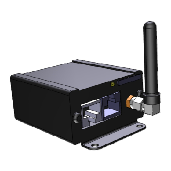
– Trennen Sie vor dem Abnehmen der Abdeckungen die Steuerung des Gerätes komplett von der Spannungsversorgung. – Überprüfen Sie die Platine auf Spannungsfreiheit. Elektrischer Anschluss Bei der Reflex Control Remote wird für die Spannungsversorgung ein externes Netzgerät mitgeliefert. Gehäuse der Reflex Control Remote. 1 RS485 Schnittstelle RJ45 Stecker 4 Antennenanschluss (GSM) 2 ... -
Page 6: Anschluss Der Rs-485-Verbindung An Die Reflex Control Basic Steuerung
Anschluss Anschluss der RS-485-Verbindung an die Reflex Control Basic Steuerung Anschlussplan der Reflex Control Basic. DIP‐Schalter 1 und 2 in aktiver Stellung 2 Anschlussklemmen für die RS‐485‐Verbindung • Der Abschlusswiderstand ist aktiviert Gehen Sie wie folgt vor: Öffnen Sie den Gehäusedeckel von der Steuerung Control Basic. Montieren Sie den Adapter im oberen rechten Bereich des Gehäusebodens. Befestigen Sie die Reflex Control Remote auf dem Adapter. Verbinden sie die Grundplatine mit der Reflex Control Remote mittels dem mitgelieferten RS485 Kabel. o Anschluss an den Klemmen 29, 30. o RJ45‐Stecker an der Reflex Control Remote Führen Sie ein LAN‐ Kabel durch eine Kabeldurchführung und verbinden Sie dies mit der Reflex Control Remote. Schließen Sie die Spannungsversorgung an. o Verwenden Sie das mitgelieferte Netzteil. Aktivieren Sie auf der Grundplatine von der Control Basic die Abschlusswiderstände. o Mit den DIP‐Schaltern 1 und 2. ... -
Page 7: Anschluss Der Rs-485-Verbindung Mit Der Steuerung Control Touch
Anschlussplan von der Steuerung Control Touch. 1 Anschlussklemmen für die RS‐485‐Verbindung 2 DIP‐Schalter 1 und 2 in aktiver Stellung • Die Abschlusswiderstände sind aktiviert Gehen Sie wie folgt vor: Öffnen Sie den Schaltschrank der Control Touch Steuerung. Montieren Sie den Hutschienenadapter an der Reflex Control Remote. Befestigen Sie die Reflex Control Remote auf der Hutschiene. Verbinden Sie die TAN‐Platine (im oberen Teil der Steuerung) mit der Reflex Control Remote mittels dem mitgelieferten RS485 Kabel. o Anschluss an den Klemmen 1,2 (TAN‐Platine) o RJ45‐Stecker an der Reflex Control Remote Führen Sie ein LAN‐ Kabel durch eine Kabeldurchführung und verbinden Sie dies mit der Reflex Control Remote. Schließen Sie die Spannungsversorgung an. o Verwenden Sie das mitgelieferte Netzteil. Aktivieren Sie auf der Grundplatine von der Control Touch die Abschlusswiderstände. o Mit den DIP‐Schaltern 1 und 2. Control Remote — 09.11.2015 Deutsch — 7... -
Page 8: Einstellungen
Überprüfen Sie die Platine auf Spannungsfreiheit. Einstellung der Abschlusswiderstände in RS-485-Netzen Beispiele zum Aktivieren oder Deaktivieren von den Abschlusswiderständen in RS‐485‐Netzen. Auf der Grundplatine der Steuerung Control Basic / Touch finden Sie die DIP‐Schalter 1 und 2 Maximale Länge von 1000 Meter für die RS‐485‐Verbindung Gerätesteuerungen mit Reflex Control Remote. Steuerung Control Basic mit Reflex Control Remote Steuerung Control Touch mit Reflex Control Remote 1 Platine der Control Remote 4 Grundplatine der Control Basic 2 ... - Page 9 Einstellungen Gerätesteuerungen mit Reflex Control Remote und I/0‐Modul oder/und Busmodul. 1 Steuerung Control Touch mit Control Remote 3 Busmodul 2 I/0‐Modul 4 Steuerung Control Basic mit Control Remote Einstellungen der Abschlusswiderstände Jumper J3 Jumper / Schalter Jumper J10 und J11 DIP‐Schalter 1 und 2 1 und 2 sowie 3 und 4 Einstellung Aktiviert Deaktiviert Aktiviert Deaktiviert Aktiviert Deaktiviert Control Remote ‐‐ ‐‐ X ‐‐ ‐‐ Control Touch ‐‐ ‐‐ X ‐‐ ‐‐ ...
- Page 10 Einstellungen Gerätesteuerungen und I/0-Module in der Master – Slave Funktionen. 000255_00 _R00 1 6 Steuerung Control Touch mit Control Remote in Steuerung Control Basic mit Control Remote in der der Master‐Funktion Master‐Funktion 2 I/0‐Modul für die Master Funktion 7 I/0‐Modul für die Master Funktion 3 Steuerung Control Touch in der Slave‐Funktion 8 Steuerung Control Basic in der Slave‐Funktion 4 I/0‐Modul für die Slave Funktion 9 I/0‐Modul für die Slave‐Funktion 5 Busmodule Einstellungen der Abschlusswiderstände Beispiel 1 Control Touch Jumper J3 Jumper/Schalter Jumper J10 und J11...
- Page 11 Einstellungen Einstellungen der Abschlusswiderstände Beispiel 2 Control Basic Jumper J3 Jumper/Schalter Jumper J10 und J11 DIP-Schalter 1 und 2 1 und 2 sowie 3 und 4 Einstellung Aktiviert Deaktiviert Aktiviert Deaktiviert Aktiviert Deaktiviert Master-Funktion: Control Basic Control Remote I/O Module...
-
Page 12: Verbindung Über Lan
Führen Sie ein LAN-Kabel über die Kabeldurchführung ein und verbinden Sie dies mit der LAN Schnittstelle. o Blinken beide LED an der LAN Buchse konnte die Reflex Control Remote sich mit dem Internet verbinden. Soll die Anlage zusätzlich zur Überwachung auch gesteuert werden muss im Servicemenü die entsprechende Einstellung aktiviert werden. -
Page 13: Verbindung Über Gsm
GSM Antenne SIM Karte Gehen Sie wie folgt vor: Öffnen Sie den das Gehäuse und trennen sie die Spannungsversorgung zur Reflex Control Remote Legen Sie eine Sim Karte in den Slot ein. Um die Verbindung über GSM herzustellen muss die beiliegende Antenne montiert werden. -
Page 14: Betrieb Der Reflex Control Remote
Betrieb der Reflex Control Remote Einstellung der LAN Betriebsmodi Grundsätzlich ist die Reflex Control Remote auf eine feste IP eingestellt. Um die Adresse zu ändern bzw. den Modus DHCP einzustellen gehen sie wie folgt vor: Verbinden Sie das Gerät über die LAN Schnittstelle direkt mit einem PC. -
Page 15: Einstellung Der Gsm Betriebsmodi
Betrieb der Reflex Control Remote Einstellung der GSM Betriebsmodi Grundsätzlich ist die Reflex Control Remote auf LAN mit fester IP eingestellt. Um die Reflex Control Remote über GSM zu erreichen gehen Sie wie folgt vor: Verbinden Sie das Gerät über die LAN Schnittstelle direkt mit einem PC. -
Page 16: Standardeinstellungen Der Reflex Control Remote
Standardeinstellungen der Reflex Control Remote Standardeinstellungen der Reflex Control Remote Grundeinstellung IP Adresse (fest) 192.168.1.234 16 — Deutsch Control Remote - 09.11.2015... -
Page 17: Anhang
Zentraler Werkskundendienst Zentrale: Telefonnummer: +49 (0)2382 7069 - 0 Werkskundendienst Telefonnummer: +49 (0)2382 7069 - 9505 Fax: +49 (0)2382 7069 - 523 E-Mail: service@reflex.de Technische Hotline Für Fragen zu unseren Produkten Telefonnummer: +49 (0)2382 7069-9546 Montag bis Freitag von 8:00 Uhr bis 16:30 Uhr Control Remote —... - Page 18 Technical data ....................................4 4 Connection .......................................5 Power supply ......................................5 Connection of the RS-485 connector to the Reflex Control Basic controller ................6 Connection of the RS-485 connector to the the Control Touch controller .................. 7 ...
-
Page 19: Information Concerning The Operating Manual
Models The Reflex Control Remote is used for monitoring and control of the pressurising and degassing stations via an existing internet connection. The following device groups with control unit are suitable for expansion with the Reflex Control Remote. -
Page 20: Technical Data
Technical data Technical data Housing Robust metal housing Width (W) 83 mm Height (H) 34 mm Depth (D) 60 mm Weight 120 g Permissible operating ‐5° C – 55° C temperature Permissible storage temperature ‐40° C – 70° C Degree of protection IP IP 65 – after installation in the controller Voltage supply 6‐30 VDC Fusing • secondary The Reflex Control Remote is fused via the control board. 4 — German Control Remote - 09.11.2015... -
Page 21: Connection
230 V power supply. – Before you remove the covers, completely isolate the device controller from the power supply. – Verify that the main circuit board is voltage-free. Power supply An external mains adapter is supplied with the Reflex Control Remote to provide power. Reflex Control Remote housing. 1 RS485 interface RJ45 jack 4 ... -
Page 22: Connection Of The Rs-485 Connector To The Reflex Control Basic Controller
Connection Connection of the RS-485 connector to the Reflex Control Basic controller Connection plan of the Reflex Control Basic. DIP switches 1 and 2 in active position 2 Connection terminals for RS‐485 connection • The terminator is activated Proceed as follows: Open the housing cover of the Control Basic controller. Install the adapter in the top right area of the housing bottom. Secure the Reflex Control Remote on the adapter. Connect the main board to the Reflex Control Remote using the supplied RS485 cable. o Connection to terminals 29, 30. o RJ45 jack on the Reflex Control Remote Route a LAN cable through a cable penetration and connect it to the Reflex Control Remote. Connect the power supply. o Use the supplied mains adapter. ... -
Page 23: Connection Of The Rs-485 Connector To The The Control Touch Controller
Connection plan of the Control Touch controller. 1 Connection terminals for RS‐485 connection 2 DIP switches 1 and 2 in active position • The terminators are activated Proceed as follows: Open the control cabinet of the Control Touch controller. Fit the top hat rail adapter on the Reflex Control Remote. Secure the Reflex Control Remote on the top hat rail. Connect the TAN PCB (in the upper part of the controller) to the Reflex Control Remote using the supplied RS485 cable. o Connection at terminals 1, 2(TAN PCB) o RJ45 jack on the Reflex Control Remote Route a LAN cable through a cable penetration and connect it to the Reflex Control Remote. Connect the power supply. o Use the supplied mains adapter. Activate the terminators on the main board of the Control Touch. o Use DIP switches 1 and 2. Control Remote — 09.11.2015 German — 7... -
Page 24: Settings
Verify that the main circuit board is voltage-free. Setting the terminators in RS-485 networks Examples for the activation and deactivation of terminators in RS–485 networks. DIP switches 1 and 2 are located on the main board of the Control Basic / Touch Maximum length for an RS–485 connection is 1000 metres Device controllers with Reflex Control Remote. Control Basic controller with Reflex Control Remote Control Touch controller with Reflex Control Remote 1 Control Remote PCB 4 Control Basic main board 2 ... - Page 25 Settings Device controllers with Reflex Control Remote and I/O module and/or bus module. 1 Control Touch controller with Control Remote 3 Bus module 2 I/O module 4 Control Basic controller with Control Remote Terminator settings Jumper J3 Jumper / Switch Jumpers J10 and J11 DIP switches 1 and 2 1 and 2 and 3 and 4 Activated Deactivate Activated Deactivated Activated Deactivate Setting d d Control Remote ‐‐ ‐‐ X ‐‐ ‐‐ Control Touch ‐‐ ‐‐ X ...
- Page 26 Settings Device controllers and I/O modules in Master – Slave functions. 000255_00 _R00 1 6 Control Touch controller with Control Remote in Control Basic controller with Control Remote in Master function Master function 2 I/O module for the Master function 7 I/O module for the Master function 3 Control Touch controller in Slave function 8 Control Basic controller in Slave function 4 I/O module for the Slave function 9 I/O module for the Master function 5 Bus modules Terminator settings, example 1 Control Touch Jumper J3 Jumper/switch...
- Page 27 Settings Terminator settings, example 2 Control Basic Jumper J3 Jumper/switch Jumpers J10 and J11 DIP switches 1 and 2 1 and 2 and 3 and 4 Setting Activated Deactivated Activated Deactivated Activated Deactivated Master function: Control Basic Control Remote I/O modules...
-
Page 28: Setting Up The Internet Connection
Settings Setting up the Internet connection Two methods can be used to create a connection to the Internet. For the Reflex Control Remote to be able to communicate, the http port and the https port must be open. http-port: 80 https-port: 443 5.2.1... -
Page 29: Connection Via Gsm
GSM aerial SIM card Proceed as follows: Open the housing and disconnect the power supply to the Reflex Control Remote Insert a SIM card in the slot. To create a connection via GSM, the enclosed aerial must be fitted. Connect the device to the power supply Follow the points described in section 6 to switch to GSM operation. -
Page 30: Operation Of The Reflex Control Remote
Operation of the Reflex Control Remote Setting the LAN operating modes By default the Reflex Control Remote is set to a fixed IP address. To change the address or set DHCP mode, proceed as follows: Connect the device via the LAN interface directly to a PC. -
Page 31: Setting The Gsm Operating Modes
Operation of the Reflex Control Remote Setting the GSM operating modes By default the Reflex Control Remote is set to LAN with fixed IP address. To connect to the Reflex Control Remote via GSM, proceed as follows: Connect the device via the LAN interface directly to a PC. -
Page 32: Default Settings Of The Reflex Control Remote
Default settings of the Reflex Control Remote Default settings of the Reflex Control Remote Basic configuration IP address (fixed) 192.168.1.234 16 — German Control Remote - 09.11.2015... -
Page 33: Appendix
Appendix Appendix Reflex Customer Service Central customer service Switchboard: Telephone number: +49 (0)2382 7069 - 0 Customer Service extension: +49 (0)2382 7069 - 9505 Fax: +49 (0)2382 7069 - 523 E-mail: service@reflex.de Technical Hotline For questions about our products Telephone number: +49 (0)2382 7069-9546 Monday to Friday, 8:00 a.m. - Page 34 Caractéristiques techniques ................................4 4 Raccordement ....................................5 Raccordement électrique ..................................5 Raccordement de la connexion RS-485 sur la commande Control Basic de Reflex ..............6 Raccordement de la connexion RS-485 à la commande Control Touch ..................7 ...
-
Page 35: Remarques À Propos Du Mode D'emploi
à portée de main près de l’appareil. Versions Le Control Remote de Reflex sert à surveiller et piloter les stations de mise en pression et de dégazage par le biais d’une connexion Internet existante. Les groupes d’appareil suivants dotés d'une unité de commande sont adaptés pour l’extension avec le Control Remote de Reflex. -
Page 36: Caractéristiques Techniques
Caractéristiques techniques Caractéristiques techniques Boîtier Boîtier métallique robuste Largeur (L) 83 mm Hauteur (H) 34 mm Profondeur (P) 60 mm Poids 120 g Température de service ‐5° C – 55° C admissible Température de stockage ‐40° C – 70° C admissible Degré de protection IP IP 65 – Après le montage dans la commande Alimentation en tension 6‐30 V CC Fusible • secondaire Le Control Remote de Reflex est protégé par fusible via la carte de la commande. 4 — Français Control Remote - 09.11.2015... -
Page 37: Raccordement
Avant de retirer les couvercles, débrancher complètement la commande de l’appareil de l’alimentation en courant. – S’assurer que la carte est hors tension. Raccordement électrique Un bloc d’alimentation externe est fourni pour l’alimentation en courant sur le Control Remote de Reflex. Boîtier du Control Remote de Reflex 1 Interface RS485 connecteur RJ45 4 Raccord d’antenne (GSM) ... -
Page 38: Raccordement De La Connexion Rs-485 Sur La Commande Control Basic De Reflex
Raccordement Raccordement de la connexion RS-485 sur la commande Control Basic de Reflex Schéma de raccordement du Control Basic de Reflex Commutateurs DIP 1 et 2 en position active 2 Bornes de raccordement pour la connexion RS‐485 • La résistance terminale est activée Procéder comme suit : Ouvrir le couvercle du boîtier de la commande Control Basic. Monter l’adaptateur dans le coin supérieur droit du fond du boîtier. Fixer le Control Remote de Reflex sur l’adaptateur. Connecter la carte‐mère au Control Remote de Reflex à l’aide du câble RS485 fourni. o Raccordement sur les bornes 29, 30. o Connecteur RJ45 sur le Control Remote de Reflex Passer un câble LAN Control Remote à travers un passe‐câble et le connecter au Control Remote de Reflex. Raccorder l’alimentation en courant. o Utiliser le bloc d’alimentation fourni. ... -
Page 39: Raccordement De La Connexion Rs-485 À La Commande Control Touch
Schéma de raccordement de la commande Control Touch 1 Bornes de raccordement pour la connexion RS‐485 2 Commutateurs DIP 1 et 2 en position active • Les résistances terminales sont activées Procéder comme suit : Ouvrir l’armoire de distribution de la commande Control Touch. Monter l’adaptateur pour le profilé chapeau sur le Control Remote de Reflex. Fixer le Control Remote de Reflex sur le profilé chapeau. Connecter la carte TAN (dans la partie supérieure de la commande) au Control Remote de Reflex à l’aide du câble RS485 fourni. o Raccordement sur les bornes 1,2 (carte TAN). o Connecteur RJ45 sur le Control Remote de Reflex Passer un câble LAN Control Remote à travers un passe‐câble et le connecter au Control Remote de Reflex. Raccorder l’alimentation en courant. o Utiliser le bloc d’alimentation fourni. Activer sur la carte‐mère du Control Touch les résistances terminales. o Avec les commutateurs DIP 1 et 2. Control Remote — 09.11.2015 Français — 7... -
Page 40: Réglages
Réglage des résistances terminales dans les réseaux RS-485 Exemples pour activer ou désactiver les résistances terminales ans les réseaux RS‐485. Les commutateurs DIP 1 et 2 se trouvent sur la carte‐mère de la commande Control Basic / Touch Longueur maximale 1000 mètres pour la connexion RS‐485 Commandes d’appareils avec le Control Remote de Reflex Commande Control Basic avec le Control Remote de Reflex Commande Control Touch avec le Control Remote de Reflex 1 Carte du Control Remote 4 Carte mère du Control Basic 2 ... - Page 41 Réglages Commandes d’appareil avec le Control Remote de Reflex et le module E/S et/ou le module bus 1 Commande Control Touch avec le Control 3 Module bus Remote 2 Module E/S 4 Commande Control Basic avec le Control Remote Réglages des résistances terminales Cavalier J3 Cavalier / Cavalier J10 et J11 Commutateurs DIP 1 et 2 Commutateur 1 et 2 ainsi que 3 et 4 Réglage Activé Désactivé Activé Désactivé Activé Désactivé Control Remote ‐‐ ‐‐ X ‐‐ ‐‐ Control Touch ‐‐ ‐‐ X ...
- Page 42 Réglages Commandes d’appareil et modules E/S dans les fonctions Maître - Esclave 000255_00 _R00 1 Commande Control Touch avec le Control Remote 6 Commande Control Basic avec le Control Remote dans la fonction Maître dans la fonction Maître 2 Module E/S pour la fonction Maître 7 Module E/S pour la fonction Maître 3 Commande Control Touch dans la fonction Esclave 8 Commande Control Basic dans la fonction Esclave 4 Module E/S pour la fonction Esclave 9 Module E/S pour la fonction Esclave 5 Modules bus ...
- Page 43 Réglages Réglages des résistances terminales exemple 2 Control Basic Cavalier J3 Cavalier/Commutateur Cavalier J10 et J11 Commutateurs DIP 1 et 2 1 et 2 ainsi que 3 et 4 Réglage Activé Désactivé Activé Désactivé Activé Désactivé Fonction Maître : Control Basic...
-
Page 44: Réglage De La Connexion Internet
Passer un câble LAN à travers le passe-câble et le connecter à l’interface LAN. o Si les deux DEL clignotent sur la fiche LAN, le Control Remote de Reflex a pu se connecter à Internet. Si le système doit également être piloté pour la surveillance, le réglage correspondant doit être activé dans le menu Service. -
Page 45: Connexion Via Gsm
Réglages 5.2.2 Connexion via GSM Control Remote de Reflex Bornes pour la connexion RS485 Antenne GSM Carte SIM Procéder comme suit : Ouvrir le boîtier et débrancher l’alimentation en courant du Control Remote de Reflex. Insérer une carte Sim dans la fente. -
Page 46: Fonctionnement Du Control Remote De Reflex
Fonctionnement du Control Remote de Reflex Réglage des modes de fonctionnement LAN Par défaut, le Control Remote de Reflex est réglé sur une IP fixe. Afin de modifier l’adresse ou de régler le mode DHCP, procéder comme suit : Relier l’appareil directement à un ordinateur via l’interface LAN. -
Page 47: Réglage Des Modes De Fonctionnement Gsm
Fonctionnement du Control Remote de Reflex Réglage des modes de fonctionnement GSM Par défaut, le Control Remote de Reflex est réglé sur une IP fixe pour le LAN. Afin de se connecter au Control Remote de Reflex via GSM, procéder comme suit : Relier l’appareil directement à... -
Page 48: Réglages Standard Du Control Remote De Reflex
Réglages standard du Control Remote de Reflex Réglages standard du Control Remote de Reflex Réglage de base Adresse IP (fixe) 192.168.1.234 16 — Français Control Remote - 09.11.2015... -
Page 49: Annexe
Annexe Annexe Service après-vente du fabricant Reflex Service après-vente central du fabricant Standard : N° de téléphone : +49 (0)2382 7069 - 0 N° de téléphone du service après-vente du fabricant : +49 (0)2382 7069 - 9505 Fax : +49 (0)2382 7069 - 523 E-mail : service@reflex.de... - Page 50 Reflex Winkelmann GmbH Gersteinstraße 19 59227 Ahlen, Germany Telephone: +49 (0)2382 7069-0 Fax: +49 (0)2382 7069-588 www.reflex.de...