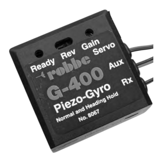
Sommaire des Matières pour ROBBE Piezo Gyro G 400
- Page 1 Einbau- und Bedienungsanleitung Installation and operating instructions Notice de montage et d’utilisation Piezo Gyro G 400 No. 8067...
- Page 2 1. Vorwort: Inhaltsverzeichnis Contents Contenu résumé Der robbe Piezo Gyro G 400 ist ein revolutionäres Präzisions - Kreiselsystem mit Piezo - Sensor für Flug- und Hubschraubermodelle. Einbau und Bedienungsanleitung Piezo Gyro G 400 (deutsch) Seite Dieser moderne Piezo - Kreisel besitzt 2 unterschiedliche Modi:...
- Page 3 Ergebnisse erzielen. Mit den beiliegenden Schaumstoffteilen können Sie das · Modell bzw. Piezo Gyro G 400 ca. 10 Sekunden nicht bewegen, Piezo Gyro G 400 Kreiselsystem auf Ihr Modell anpassen. Gute Ergebnisse wurden auch mit dem 3,2 mm führt seinen Nullabgleich durch.
- Page 4 Wie bereits eingangs beschrieben, wird in diesem Modus sehr gut die Heckauslegerposi- tion beibehalten. Dieser neue Modus bietet folgende Vorteile: Wie in der Skizze 1 gezeigt, den Piezo Gyro G 400 zwischen das Heckrotorservo und den · Für den Einsteiger ergibt sich nun die Möglichkeit, sich völlig auf die anderen Grundfunk- Empfänger stecken und den Anschluß...
-
Page 5: Sonstige Hinweise
2 x 2 selbstklebende Dämpfungsschaumstoffstreifen 1 x Bedienungsanleitung Wie in der Skizze 1 gezeigt, den Piezo Gyro G 400 zwischen das Heckrotorservo und den Empfänger stecken. Der Anschlußstecker „Aux“ bleibt in dieser Anschlußvariante frei. robbe Modellsport GmbH & Co. KG Wenn der Zusatzkanal nicht über die Fernsteuerung angeschlossen werden kann, arbeitet... - Page 6 · Do not touch the model or Piezo Gyro G 400 for about 10 seconds while the Piezo This modern piezo-gyro provides two different modes of operation: Gyro G 400 carries out its zero calibration procedure.
- Page 7 -> tail rotor mixer) should also be switched off. Connect the Piezo Gyro G 400 between the tail rotor servo and the receiver as shown in Sketch 1, and connect the „Aux“ connector to a vacant slider channel (e.g. Channel 5).
- Page 8 If not, ope- ferences in the radio control system’s neutral signal. rate the „REV“ switch on the Piezo Gyro G 400. Note: if you use the „REV“ switch on ·...
-
Page 9: Temperature Adjustment
Made in Germany No. 8067 7. Contents of set Servos recommandés 1 x Piezo Gyro G 400 Alimenté par 4,8 volts (4 éléments Cd-Ni, Ni-MH): 2 x 2 self-adhesive strips of damping foam servo S 9253 réf. F 1278 voie 4... - Page 10 De bons résultats ont également été obtenus avec le des, le gyroscope piézo G 400 réalise un calibrage à zéro double face de 3,2 mm d’épaisseur de la Sté 3M (robbe réf. 5014). Nous vous prions donc ·...
- Page 11 8067 8067 Piezo Gyro G 400 Piezo Gyro G 400 4. Branchement et mise en service n’est pas le cas, inverser la course du servo au niveau de l’émetteur · contrôle de la direction de l’effet du gyroscope (commutateur REV) : déplacer la flèche À...
-
Page 12: Autres Remarques
8067 8067 Piezo Gyro G 400 Piezo Gyro G 400 Pour la mise en service procéder comme indiqué sous 4.1. 5. Généralités · activer le mode „tenue de cap“ (voie à curseur 5 en butée) · attention au rotor arrière, il se déplace dans un sens ou dans l’autre en fonction de l’im- 5.1 Condition préalables imposées au modèles... - Page 13 Sous réserve de d’erreur et de modification technique. Copyright robbe-Modellsport 2003 Copie et reproduction, même d’extraits, interdites sans autorisation écrite expresse de la Société robbe-Modellsport GmbH & Co. KG robbe Modellsport GmbH & Co. KG Metzloserstr. 36 Telefon: 06644 / 87-0...


